
B3.3T Jeep YJ


Registered User
Joined: Oct 2009
Posts: 40
Likes: 0
From: Minnesota
Thanks. Just out of curiousity, what type of setup did you use for making the maps? Specifically curious as to how you accurately measure the fuel consumed. Do you have some type of highly accurate flow meter on the injection pump in/out ports and subtract those readings to get the consumed fuel?
Also curious if you know what would happen to those BSFC numbers when the power is turned up by increasing the max fuel screw. It looks like the BSFC is approaching an asymptotic thermal efficiency point at its rated output but I'm curious if it eventually rolls over and starts becoming less efficient. And how would one be able to tell that? I'm assuming things like the boost/egt/black smoke would give some clues, but I'm not sure what the hard numbers look like.
Thanks again.
Your numbers should increase slightly if you turn up the fuel, or be relatively the same. What happens is, you are using more fuel, but at the same time creating more power. But the two are not linear, so your fuel consumption should increase faster than the power, with the same adjustments. EGTs are probably your most accurate way of looking at it on your vehicle. So, if you increase the screw, it will increase both fuel consumption and power, and you should see an increase in EGTs. To what extent the EGTs will increase I wouldn't know.
At a certain point, you will probably reach the limit on the injectors, so no matter how far you turn the screw on the injection pump, the injectors only flow so much. I think you won't see a decrease in power when you've hit this point, but you will increase the screw and not see an increase in power, due to the limitations after the injection pump.
Keep in mind other things are still factored in way beyond this... Injection pump wear, pump timing (i've had some B3.3 pumps with bad timing do some weird stuff, usually tons of white smoke aka excess fuel), the injector size (again), the size of the pump/pump rotor, pressure and such, etc. etc.

Registered User
Joined: Oct 2009
Posts: 40
Likes: 0
From: Minnesota
Just an update on my engine, here is a video with the engine on the garage floor. Next up for this is do work on the turbocharger...
click me --> Cummins A2300 <-- click me
I know it's not a b3.3, but its cummins, and the install is generally the same as everyone else on this thread basically.
click me --> Cummins A2300 <-- click me
I know it's not a b3.3, but its cummins, and the install is generally the same as everyone else on this thread basically.

Registered User
Joined: Dec 2009
Posts: 11
Likes: 0
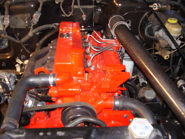
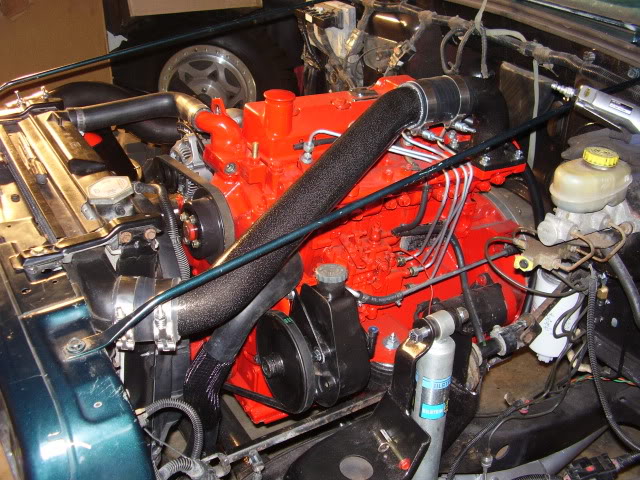
Thought you guys would enjoy seeing another build... I bought the engine used, fully rebuilt it, and finally fired last night. Still have some tweaking to do (way too much fuel).
TDI-Wyse, how many turns out did you end up on your IP pressure settings? And is that from hard stop or from factory, which I have no clue what it is.
Enjoy:
TDI-Wyse, how many turns out did you end up on your IP pressure settings? And is that from hard stop or from factory, which I have no clue what it is.
Enjoy:

Registered User
Joined: Dec 2009
Posts: 11
Likes: 0
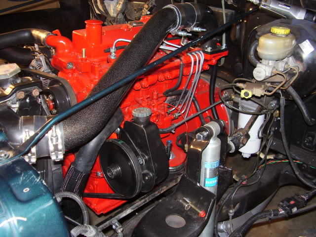
The power steering pump is a standard Saginaw P-pump style used on lots of cars/brands in the 70's and 80's. It was just easy to adapt because of the v-belt configuration in conjunction with the double groove crank pulley. I don't have a build thread yet, but eventually I'll post it up. Gotta get her rolling first!

Registered User
Joined: Apr 2009
Posts: 28
Likes: 0
Red Smoke, I'll be interested to see what happens with the TJ. I notice you still have the factory computer hooked up. Are you planning to keep it? You've got a similar Turbo build up to what I would do to keep the profile low and fit without cutting the hood.
Let us know when you get a build thread up.
Anyone have a clue what separates an industrial/agricultural diesel engine from an automotive diesel?
Let us know when you get a build thread up.
Anyone have a clue what separates an industrial/agricultural diesel engine from an automotive diesel?
Registered User
Joined: Dec 2009
Posts: 11
Likes: 0
I notice you still have the factory computer hooked up. Are you planning to keep it? You've got a similar Turbo build up to what I would do to keep the profile low and fit without cutting the hood.
Anyone have a clue what separates an industrial/agricultural diesel engine from an automotive diesel?
Anyone have a clue what separates an industrial/agricultural diesel engine from an automotive diesel?
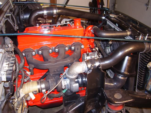
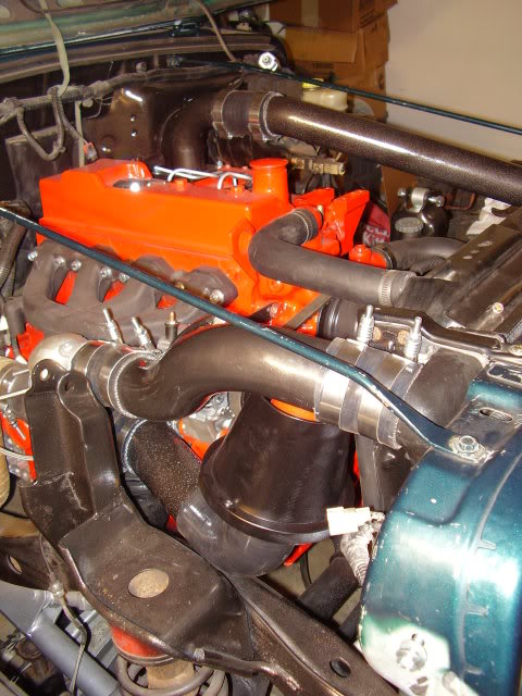
As far as the turbo configuration, Cummins offers a low mount turbo option but I didn't want to spend the $$ to buy all the required components so I made my own. It involves flipping the stock manifold, and changing the orientation of the turbine housing, bearing housing and compressor housings, and then running custom drain and feed lines. Overall, not that difficult as long as you aren't afraid of opening up turbochargers. BTW this is not the stock turbo for this engine, but actually a custom one I built which should make 20-25psi with proper fueling. That's why the compressor housing uses marmon joints.
On the ag vs automotive engines, they're obviously certified to different emissions levels, but the most noticeable difference is the governor load curves. Some governor curves won't be very friendly to automotive type driving as they're meant to run at PTO or rated speeds (automotive are meant to control engine speed while AG is designed to control torque). Just my understanding of it...

Thread Starter
Registered User
Joined: Mar 2004
Posts: 380
Likes: 1
From: Iowa
That is pretty. Looking forward to hearing updates from you.
As far as the fuel screw, I don't recall how many turns i did. But I can tell you I went to the point where the rpm's at idle started to increase and the rpm's would "hang" for a sec after blurping the fuel pedal. Then I turned the screw back about 1/4 to 1/2 turn.
As far as the fuel screw, I don't recall how many turns i did. But I can tell you I went to the point where the rpm's at idle started to increase and the rpm's would "hang" for a sec after blurping the fuel pedal. Then I turned the screw back about 1/4 to 1/2 turn.

Registered User
Joined: Dec 2009
Posts: 11
Likes: 0
Thanks for the props guys. It's nice to get approvals from the "pioneers!"
Anybody try adapting a larger alternator? I think the mounting system is pretty standard for automotive alternators. I'm worried that the little 60amp is going to struggle with the electric vacuum pump, and worse yet, winch.
Anybody try adapting a larger alternator? I think the mounting system is pretty standard for automotive alternators. I'm worried that the little 60amp is going to struggle with the electric vacuum pump, and worse yet, winch.
Registered User
Joined: Apr 2009
Posts: 28
Likes: 0
Overall, not that difficult as long as you aren't afraid of opening up turbochargers.
On the ag vs automotive engines, they're obviously certified to different emissions levels, but the most noticeable difference is the governor load curves. Some governor curves won't be very friendly to automotive type driving as they're meant to run at PTO or rated speeds (automotive are meant to control engine speed while AG is designed to control torque). Just my understanding of it...
On the ag vs automotive engines, they're obviously certified to different emissions levels, but the most noticeable difference is the governor load curves. Some governor curves won't be very friendly to automotive type driving as they're meant to run at PTO or rated speeds (automotive are meant to control engine speed while AG is designed to control torque). Just my understanding of it...
Thanks for the information on ag vs auto configuration. I'm of the opinion that many ag or industrial engines could be converted with some simple mods. Might make an interesting senior project.

Registered User
Joined: Dec 2009
Posts: 11
Likes: 0
Which Chrysler trans are you using? If it's an AX15/NV3550/NSG370 it will be different than an AX5/Peugot trans. I don't have an actual measurement of mine (NSG370) - we just CMM'd the back side of the block and then had a prototyping shop make the aluminum adapter and flywheel adapter such that it mimics the rear face of block on a 4.0L engine.
Registered User
Joined: Oct 2009
Posts: 40
Likes: 0
From: Minnesota
AX15. I haven't tried mating them up yet, still waiting on my flywheel and clutch. And I can't find (online anywhere) any measurement on what it should be. There should be a standard measure I would think, so that as long as I have that distance, the tranny and clutch would bolt right up no prob.
Just thought I'd try to make it easy, but will probably end up bolting it all together a few times on and off haha
Just thought I'd try to make it easy, but will probably end up bolting it all together a few times on and off haha
Registered User
Joined: Dec 2009
Posts: 11
Likes: 0
If you measure the front face of trans (FFOT) to the release bearing surface, that will give you an approximate measurement which you add to the stackup between the clutch finger height (installed over disc on flywheel) and the flwwheel surface which mates to the crank palm. Kind of a long way around the block, but it would give you a starting point if you're thinking of making your own adapters.