When you click on links to various merchants on this site and make a purchase, this can result in this site earning a commission. Affiliate programs and affiliations include, but are not limited to, the eBay Partner Network.
1993 D250 KPD inspection, VE pump reseal and related concerns/maintanance
1st Gen. Ram - All TopicsDiscussion for all Dodge Rams prior to 1994. This includes engine, drivetrain and non-drivetrain discussions. Anything prior to 1994 should go in here.
1993 D250 KPD inspection, VE pump reseal and related concerns/maintanance
My goal here is to document my KDP inspection that I've opted to do along with the now non optional task of a VE pump reseal. I invite any and all commentary and criticism that will eventually aid someone needing to do this in the future (including me!). I'm basing my process on NJTman's write up and only intend for my write up to be a supplement to that. Also if anyone has any ideas of what to check along the way, tell me.
My reasoning for bundling these jobs includes the assumption that with the radiator and timing cover off, I will have an easier time making sure all timing marks are in place when everything goes back together with the injection pump. Also, there are 207k miles on the truck and i don't know the history before 195k miles. And lastly, since my mobility is limited due to some back problems, I'm game for removing anything that makes it an easier fight even if it requires more time to complete.
peaking of making things easier I can't speak highly enough of the value in having a little impact driver set up as a socket wrench. Especially for removal of parts like the idler pulley. I had mine off in a minute while holding it loosely still with my other hand. Not possibly with ratchet wrenches.
Mine has a chuck that fits 1/4" hex bits and 1-2" square drive sockets.
So far, Ive removed the radiator, idler pulley and intake and intercooler hoses to turbo to get lower radiator hose clamp easier. I'm about to get to vibration damper on the crank and also check idler pulley bearing. It doesn't mention in the FSM but does the position of that need my attention or is there only one way to put it back on? I'd like to get the timing cover off and see what seal is on the crank nose (with or without wear sleeve) so I can have that ordered tonight.
I plan to set to TDC before I take VE pump off, will I need to that before or after timing cover and crank pulley is off? Or can i do that without marks on vibration damper. What is an acceptable way to bar the engine if I don't have the special tool?
Some things to note so far is the belt tensioner needs to be replaced and there is oil in the piping to intercooler.
Tensioner pulley too close to block, causing belt to fall forward and cut into tensioner arm.
More pics later. Going to do some more work and update this PM.
I doubt the tensioner itself is the problem.....more then likely the idler puller is shot. I had 2 pulleys go on me last year. They just un-bolt....and install a new one. And the tensioner can only be installed one way, there is a small tab on the back that goes in a notch on the motor.
The oil in IC piping most likely means that your turbo needs a rebuild.
I have never timed a motor or IP when doing a re-seal job....and I've done a number over the years. Just make sure the key on the IP lines up with the keyway in the timing gear and install.
Make sure you clean and loc-tite the case bolts when you have the timing case open.
I doubt the tensioner itself is the problem.....more then likely the idler puller is shot. I had 2 pulleys go on me last year. They just un-bolt....and install a new one. And the tensioner can only be installed one way, there is a small tab on the back that goes in a notch on the motor.
and do you mean the idler pulley bearing is shot? The arm of the tensioner wobbles on the base that bolts to engine.
i noticed how the tensioner went on, i was asking what about the vibration damper on the crank?
An easy way to turn the motor over once the front is stripped down is to just put the dampener back on loosely and turn it by hand. It's not all that hard and you just need to get to TDC if that's your goal. You do not need the motor at TDC though UNLESS the injection pump gear comes unmeshed in which case you need the motor at TDC to line up the timing marks. The pump can only go into the gear one way, you cannot put it back on wrong. It is keyed and there is only one key slot in the gear.
I started with draining and removing the radiator. I didn't have a great way to divert it from pouring onto the frame but I suggest figuring that out first.
I took the turbo to intercooler pipe off to access lower radiator hose spring clamp with 24" channel locks. I also thought it was a good idea to check inside the piping. There is oil. A ml or two resting in the first run of the first boot towards the turbo and a tacky even coating in the boots and fittings.
To remove the fan, I used a cold chisel to tap the corners of the LH threaded fan nut clockwise. This loosened the nut and i was then able to remove the fan with large channel locks.
Next I removed the fan bearing, crank position sensor, and tensioner arm which has a 3/8" square recess that allows for you to unload the tension with a ratchet to remove the belt.
turbo to intercooler pipe removed
Reminder: remove towel before reassembly
CPS and vibration dampener caked in oily dirt.
Fan bearing unit.
Tensioner arm
Last edited by RamDodgeSam; Jan 14, 2017 at 02:19 PM.
Reason: Add pics
With the vibration damper off, you could just run a bolt back into the crank and turn it clockwise with a breaker bar. Once you get it to TDC, just give the handle a quick smack to loosen the bolt again.
As far as I know, the damper can go on in any position. There are no timing marks.
I used Dave's suggestion of using a doubled over business card to space the crank sensor when reassembling and it worked just fine.
I had some trials getting the vibration dampener off. With a friend turning, I managed to lock engine in TDC with locating pin and tried gently to remove the four crank bolts with 15mm socket. It felt like too much force was put on the locking pin so I disengaged it and made a tool with some 1 1/4" tubing scrap. It needed a slot cut through and crescent removed from one remaining side to fit in place over the damper. It pressed on the cross member with force displaced across a 1x4 scrap and some shimming. I removed the water pump for inspection and easier access to vibration dampener.
That tool held the crank just fine on its own but I broke a 3/8" SK 15mm 12 point socket. ... I know i was pushing its limits. And turns out I have an odd 1/2" drive 15mm socket which could have avoided breaking the SK. The bolts came out with little strength pulling on an 18" breaker bar.
Once that wheel was loose, I tried using it one last time to turn the engine to engage the locking pin but I think I had put too much force on it earlier and perhaps disfigured it because it will not engage the back of the cam gear now. I now have the timing case off and can see the timing marks and don't reckon I need to use the locking pin at this point anyway. Again, this is only of any concern to me because I will be removing the injection pump for a reseal during this job.
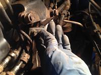
Homemade tool engaging vibration dampener.
Homemade tool to lock crank in place. made of 1 1/4" square tube
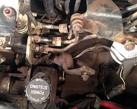
TDC locating pin behind cam gear between VE pump and PS pump
Using a 16mm socket, I loosened filltube bracket then removed the 18 13mm head screws that held the timing cover on and organized them on a cardboard sheet. The crank nose has noticable wear from a previously incorrectly installed seal. About an inch of te contacting lip is folded back (towards front of truck).
Dragging my fingernail across the entire wear surface I can feel a groove. Probably need a wear sleeve?
The KDP is snuggly sitting in the bottom of his hole. I'll photo what i do to retain it. The timing case was sealed with some silicone, so its been removed i suspect but there's no evidence of any effort to secure the KDP.
Would anyone care to discuss the need or practicality of inspecting the cam at this point (207k miles)? I needed to check valve lash anyway. I'll inspect the oil pump for sure.
Timing cover bolts stored with all brackets on cardboard sheet to keep in order.
Crankshaft nose wear.
Front crank seal that I'm replacing. Shows incorrect install.
The timing case bolts you will find are one of three different sizes. You have the two very long ones for the position sensor then the rest are either long and short. The shorts will not thread at all into the wrong hole so no worries about putting them where they don't go.
KDP looks like it hasn't moved since the factory. I'm going to round off a punch head to make a mini 1/16" peen and secure it that way. I don't think it's good to use a center punch because a point is more likely to create cracks in the cast aluminum.
I'll consolidate all current questions and concerns here.
1. tensioner arm wobbly and its pulley surface is deformed by misaligned belt
2. the fan pulley bearing feels rough - i can feel the ball bearings
3. Turbo needs rebuilding
4. cooling system is filthy. planning to do 6 month coolant change intervals for a couple years instead of aggressively flushing all at once and possibly loosening up big deposits.
5. crank nose wear seems to require wear sleeve
6. water pump turns freely can feel some "texture" in the rolling but pump is not weeping yet
7. should i have the radiator professionally flushed or just clean it slowly with frequent coolant changes?
8. I actually have a bosch pop tester and injector shims and may end up pop testing and balancing injectors.
any tips on my image management are appreciated. trying to figure out how to make them thumbnails linked to larger images or just smaller within the thread. with the images already uploaded, is there a way of making them smaller without editing and re uploading?
edit: i just resized and uploaded all the pictures that i could still edit so hopefully less annoying to read.
Try this, attach them to the post with the paperclip icon above ( in full reply, not quick reply ) and then upload them to DTR. Then you can click on it again and put them where you want them. I usually try and upload them in sequence, then attach them all at once and then go back and put any narrative in between.
Yesterday provided more time to work on the truck. I peened around the KDP and was able to remove the VE pump.
Taking pictures, I went along and disconnected all of the lines. I use a 1990 FSM and it looks like the throttle linkage bracket is different. Also rear support bracket couldn't be removed without removing the PS pump, so I removed all but the one covered bolt and swung the VE pump support back and out of the way to access the injector line flare nuts. I haven't seen this specific suggestion before but it helped speed things along for me a great deal.
I started taking off the isolation brackets on the lines close to the pump. It worked out that even though I ended up taking all the lines off anyway (I kept them in the two groups of three) the lines were easier to move around and out of the way at the back of the pump until all flare nuts were loose.
The bottom nut took about 45 minutes to get off. I had a 3/8' drive 1/2" crows foot wrench, so it was a little tight on the 13mm nut. That worked out well actually i was able to press the wrench on the nut and let go without it falling off. I was doing it completely blind and kneeling on the front portion of the frame. I was able to get it mostly by hand once it was cracked but there were some rough spots and I used the crows foot as a tiny stubby wrench to turn the tight spots. I've heard a crescent shaped wrench works well. I'll make some sort of tool before I do it that way again.
After the pump was all disconnected, I cracked the 24mm gear nut and backed it off just a bit so that it was protruding past the pump spindle. I used that nut surface to tap the spindle off of the pump. I didn't have a gear puller and I was sure with several light taps it would come off and it did. YMMV
I put the seal kit provided plugs over the holes and took everything to wash. The cardboard I used to organize the bolts worked out well for cleaning. Since the solvent didn't make the cardboard soggy, I just had them in the parts washer with all the other metal parts.
I read a thread on here where someone suggested just setting the front seal in further to a smooth part of the crank nose. Does anyone have experience with that?
I noticed my timing cover has the original gasket + some RTV or silicone type thing. If I take off the old gasket and just use RTV sealant that will put me a little off the worn part. Between that and setting the seal in further ... not sure if it will work though.
Edit: looking at the shiny part of the crank and considering where the groove is worn, i don't think i'll need the wear sleeve. that groove was created by part of the seal being bent back and is at the very front of crank. If installed correctly, a new seal will not ride on the groove. Sweet.
I started just removing the PS/Vacuum pump when pulling/installing IP's. Takes about 10 min to remove the whole PS assembly, then less then a minute to spin out that lower IP bolt.....you end up time ahead....


 ... I know i was pushing its limits. And turns out I have an odd 1/2" drive 15mm socket which could have avoided breaking the SK. The bolts came out with little strength pulling on an 18" breaker bar.