
APPS High Idler

Thread Starter
Registered User
Joined: Nov 2005
Posts: 84
Likes: 0
From: North Country
ib516,
I'm not really looking for something that the ECM will do all by itself. It helps to get it up to a safe temp, but then it kicks off. I'm thinking something to keep the RPMs up high enough to warm the cab. I spoke with a member who has already devised a system similar to what I was thinking. After reviewing what he wrote, I don't think I would be offering these for sale. Although, he might be interested in such an ordeal. The idea should still be to have an affordable electronic high idler that is easy to install. I just wanted to make my intentions public so that there is no confusion later on.
I do still plan to desing an enclosure that compliments the interior layout of the truck. I was thinking about using the pocket for the heated seat controls, but that's too handy for the storage of my cellphone. I could conceivably design something that fits inside the cupholder or one of the center vents. The key thing is that it has to look like it belongs there.
But I'm putting the proverbial cart before the horse here. I think the wiring is going to be relatively simple, but I still have to get that ironed out. I do have a wiring digram from a 2000. That particular diagram has no wire colors with it. It's getting cooler around here, so I need to get something done soon.
Thanks you all for your continued help.
Sean

Registered User
Joined: Jan 2005
Posts: 233
Likes: 0
From: East Bound and Down Loaded Up and Truckin'
ib516,
I'm not really looking for something that the ECM will do all by itself. It helps to get it up to a safe temp, but then it kicks off. I'm thinking something to keep the RPMs up high enough to warm the cab. I spoke with a member who has already devised a system similar to what I was thinking. After reviewing what he wrote, I don't think I would be offering these for sale. Although, he might be interested in such an ordeal. The idea should still be to have an affordable electronic high idler that is easy to install. I just wanted to make my intentions public so that there is no confusion later on.
I do still plan to desing an enclosure that compliments the interior layout of the truck. I was thinking about using the pocket for the heated seat controls, but that's too handy for the storage of my cellphone. I could conceivably design something that fits inside the cupholder or one of the center vents. The key thing is that it has to look like it belongs there.
But I'm putting the proverbial cart before the horse here. I think the wiring is going to be relatively simple, but I still have to get that ironed out. I do have a wiring digram from a 2000. That particular diagram has no wire colors with it. It's getting cooler around here, so I need to get something done soon.
Thanks you all for your continued help.
Sean
I'm not really looking for something that the ECM will do all by itself. It helps to get it up to a safe temp, but then it kicks off. I'm thinking something to keep the RPMs up high enough to warm the cab. I spoke with a member who has already devised a system similar to what I was thinking. After reviewing what he wrote, I don't think I would be offering these for sale. Although, he might be interested in such an ordeal. The idea should still be to have an affordable electronic high idler that is easy to install. I just wanted to make my intentions public so that there is no confusion later on.
I do still plan to desing an enclosure that compliments the interior layout of the truck. I was thinking about using the pocket for the heated seat controls, but that's too handy for the storage of my cellphone. I could conceivably design something that fits inside the cupholder or one of the center vents. The key thing is that it has to look like it belongs there.
But I'm putting the proverbial cart before the horse here. I think the wiring is going to be relatively simple, but I still have to get that ironed out. I do have a wiring digram from a 2000. That particular diagram has no wire colors with it. It's getting cooler around here, so I need to get something done soon.
Thanks you all for your continued help.
Sean
If you get the flash from the dealer for the TSB, it will warm up the cab. My roommate has it on his truck. With the remote start all you have to do is push the start button then the pickup with high idle and depending how far north in NorthCountry you are it will go into 3 cylandar mode. thus warming the engine up faster to warm up the cab. One other thing it does is when you leave your truck running all winter you don't get that carbon build up on your valves. My roommate has driven somewhere got out of his truck and came back out and it was high idling. The flash works for what you want and you will not srcew up you APPS in the process.
Aaron

Registered User
Joined: Sep 2004
Posts: 963
Likes: 0
From: Folsom CA
Rockjeep,
Do you have any pics your setup? From what I can see it makes no difference how the pot is hooked up, as long as the center leads of both the pot and the APPS's pot are on the same wire. Is this correct? I'm still thinking something with a relay for for the sake of both safety features (parking brake interlock, or nuetral safety switch) and the ability to trigger it via remote. I think you could just hook the +5V and the return side of the APPS to a DPDT relay for switching on and off. So, then you could set your idle where you want it and turn it on and off by a toggle switch. Does this sound reasonable?
Thanks again for all the help.
Sean
Thread Starter
Registered User
Joined: Nov 2005
Posts: 84
Likes: 0
From: North Country
Rockjeep,
That's what I was thinking. If I wired the relay so that the second pot was only in the circuit with power applied to the relay, then there will be no excess resistance in the circuit to cause problems with the APPS. I have a pretty good feeling about how this is set up.
Aaron,
I think I saw the TSB sticker for the ECM flash on my core support. I'll have to look at it a little closer. It would definately help in the winter, but I'm also thinking about summer. It would be nice to idle up and get the A/C going good and cold. I have a high idle setup on my Tahoe, and I love it. It's really nice for those times when you know your going to be sitting for a while, but still want to have the climate control going. I also appreciate the concern for my APPS's well being. But, I have learned a very valuable lesson in electronics... "Once you let the smoke out, you cant put it back in." Basically, you need to be absolutely certain you know what you're doing before you strip the first wire. That's what I'm trying to do here, be absolutely certain.
On a side note, I have completed a wiring diagram. Anyone that wants to review or critique it, please do so. I wouldn't have gotten this far without the help of others, so this is me trying to give a little something back.
Thanks for all the help guys
Sean
[IMG] [/IMG]
That's what I was thinking. If I wired the relay so that the second pot was only in the circuit with power applied to the relay, then there will be no excess resistance in the circuit to cause problems with the APPS. I have a pretty good feeling about how this is set up.
Aaron,
I think I saw the TSB sticker for the ECM flash on my core support. I'll have to look at it a little closer. It would definately help in the winter, but I'm also thinking about summer. It would be nice to idle up and get the A/C going good and cold. I have a high idle setup on my Tahoe, and I love it. It's really nice for those times when you know your going to be sitting for a while, but still want to have the climate control going. I also appreciate the concern for my APPS's well being. But, I have learned a very valuable lesson in electronics... "Once you let the smoke out, you cant put it back in." Basically, you need to be absolutely certain you know what you're doing before you strip the first wire. That's what I'm trying to do here, be absolutely certain.
On a side note, I have completed a wiring diagram. Anyone that wants to review or critique it, please do so. I wouldn't have gotten this far without the help of others, so this is me trying to give a little something back.
Thanks for all the help guys
Sean
[IMG]
 [/IMG]
Registered User
Joined: Apr 2004
Posts: 156
Likes: 0
From: Rio Rancho, NM
I'd also like to see if anything else has been done with this. I've got my FSM here and it looks like for a 2001 the APPS pinout is as such:
Pin 1 - BBK/LB Sensor Ground
Pin 2 - BLG/DB Idle Validation Switch No. 2
Pin 3 - BLB/BK Accelerator Pedal Position Sensor Signal
Pin 4 - BBK/YL Accelerator Pedal Position Sensor Ground
Pin 5 - BDB/WT Accelerator Pedal Position Sensor Supply
Pin 6 - BBR/OR Idle Validation Switch No. 1
So could someone with a little more knowledge give a little insight as to where all this hooks up. in looking over the wiring diagram, I think I understand that the dual pole dual throw relay will use the ground to energize its self. It looks as though both Poles are connected to the sensor supply and sensor grounds. The POT is connected as such:supply and ground wires for sensor connected to the relay on the two throws and output from the POT to the signal wire. What I don't understand is why the 2k ohm resistor is needed in between the output of the additional POT and the signal headed back to the ECM? Sorry for the long post but I'd love to beable to have a working high idle that isnt dependant on a bunch of predetermined varibles in the ECM.

Registered User
Joined: Sep 2003
Posts: 2,534
Likes: 0
From: Plano, TX
Im going to dig out my shop manual tonight for a schematic.......cant be all that hard to rig up really......still would like to see if this can work.......but right now i got a 2WL switch on the brain........
Registered User
Joined: Apr 2004
Posts: 156
Likes: 0
From: Rio Rancho, NM
Subdieselmech,
You said you talked to someone on the board who was either all over this project or willing to manufacture. Whould you care to give me the name and contact info of that person either by PM or posted here so that all of us interested can get something going??
You said you talked to someone on the board who was either all over this project or willing to manufacture. Whould you care to give me the name and contact info of that person either by PM or posted here so that all of us interested can get something going??

Banned
Joined: Mar 2005
Posts: 1,057
Likes: 0
Guys, guys, guys.....
This has been done for a long time. I am not certain of it's operation, but our beloved comrade Marine has one on his truck. He can verify, but I believe it allows you to take control of the idle RPM by utilizing the cruise controls. It is very cheap to do and a complete kit was sold by a member of the TDR a few years back. Marine sent me the information, but I somehow misplaced it and then the weather turned warmer so I forgot about it.
Heck, here is a picture of its connection at the APPS from Marine's gallery.....
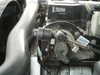
Registered User
Joined: Apr 2004
Posts: 156
Likes: 0
From: Rio Rancho, NM
That looks like a an old chevy stepper motor. Basically pushes the throttle down for you via the throttle lever on the APPS. I guess it would work ok but I think an electronic solution would be a little less cumbersome and in the end less likely to fail, because you arent adding any additional moving parts. I'd love to hear form Marine on its functionality and if it is indeed adjustable via the cruise control.

Registered User
Joined: Jan 2004
Posts: 449
Likes: 0
I agree it looks like a solenoid off a carb. That has been done several times and I believe it was Harold Bowers who was selling them at one point. I don't beleive they were adjustable with the CC switches as there was only an on and off position.
Registered User
Joined: Sep 2003
Posts: 2,534
Likes: 0
From: Plano, TX
Would this be to knock down the 12V to the 5 volts that most TPS use to work with? OR to keep from running WOT with the High idle? Am i off base here? BUT im not an Electrical Engineer by any means....