
VSS wiring

Thread Starter
Registered User
Joined: Mar 2008
Posts: 4,389
Likes: 114
From: Orange County, California
Ok fellas, I've been hunting through pages and pages of my FSM as well as countless threads regarding anything "VSS" or "speed sensor" related. I'm trying to find which of the wires carries the signal and the other the ground. Is the circuit going to be picky about what wire receives a signal or ground?
Thread Starter
Registered User
Joined: Mar 2008
Posts: 4,389
Likes: 114
From: Orange County, California
I was thinking the same thing. I did find the wiring diagram in my FSM for both plugs in the back of the instrument cluster. The "speedometer speed sensor" it said was a 20ga. white wire with an orange tracer. I just didn't know if it was the same color all the way through the harness to the plug at the transmission. Since the wires were covered in years of grime, I couldn't see a color but I was able to identify the signal and ground wires specifically by checking continuity between the plug at the transmission and the white/orange wire at the instrument cluster.
The reason I asked is because I'm using this kit from Dakota Digital to drive my speedometer:
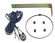
The install instructions don't specify which wire is which and that is why I assumed because it's an AC signal, that it wouldn't matter how it's wired.
The guys at Dakota Digital told me that they've had success driving OEM Chrysler speedometers using this pick-up coil on the driveshaft alone. However, I think that the older cars are different than our trucks because I temporarily installed the magnets and wired the pick-up coil exactly as the instructions say to with magnets at 12, 3, 6 and 9 o'clock positions giving an 8,000ppm signal and the pick-up coil 3/4" away from the driveshaft (seems quite far to me) yet, I still get nothing on the speedometer.
Assuming the pick-up alone wouldn't work, I also bought their speedometer signal interface which, when set up for the right application/parameters, will calibrate a low speed signal (4,000ppm-8,000ppm) for an OEM or aftermarket speedometer.

I plan to call Dakota Digital on Monday and try to clarify the 3/4" spacing between the pick-up coil and driveshaft. Unless the coil is just that sensitive, I'm not sure. As for the signal interface box, I think my only and easiest option would be to cut the white/orange wire behind the plug and run a loop to the box rather than trying to trace the wire through the factory harness to underneath the truck. Only because I'd like to keep the box inside the cab, probably under the dash, for ease of adjustments. If any are needed for a change in tire size, I can reach under the dash and adjust the speedometer up or down while I'm driving.
So that's my latest project. It's been a long time coming and I've needed to get it done for the longest time. My speedometer over the last few years has been what gear I'm in and how many RPM's the motor's turning after taking mental notes when driving by roadside radars that display your speed . It's worked though. No speeding tickets whatsoever. Even though I know I've been well above them before
  .
.
The reason I asked is because I'm using this kit from Dakota Digital to drive my speedometer:
The install instructions don't specify which wire is which and that is why I assumed because it's an AC signal, that it wouldn't matter how it's wired.
The guys at Dakota Digital told me that they've had success driving OEM Chrysler speedometers using this pick-up coil on the driveshaft alone. However, I think that the older cars are different than our trucks because I temporarily installed the magnets and wired the pick-up coil exactly as the instructions say to with magnets at 12, 3, 6 and 9 o'clock positions giving an 8,000ppm signal and the pick-up coil 3/4" away from the driveshaft (seems quite far to me) yet, I still get nothing on the speedometer.
Assuming the pick-up alone wouldn't work, I also bought their speedometer signal interface which, when set up for the right application/parameters, will calibrate a low speed signal (4,000ppm-8,000ppm) for an OEM or aftermarket speedometer.
I plan to call Dakota Digital on Monday and try to clarify the 3/4" spacing between the pick-up coil and driveshaft. Unless the coil is just that sensitive, I'm not sure. As for the signal interface box, I think my only and easiest option would be to cut the white/orange wire behind the plug and run a loop to the box rather than trying to trace the wire through the factory harness to underneath the truck. Only because I'd like to keep the box inside the cab, probably under the dash, for ease of adjustments. If any are needed for a change in tire size, I can reach under the dash and adjust the speedometer up or down while I'm driving.
So that's my latest project. It's been a long time coming and I've needed to get it done for the longest time. My speedometer over the last few years has been what gear I'm in and how many RPM's the motor's turning after taking mental notes when driving by roadside radars that display your speed
. It's worked though. No speeding tickets whatsoever. Even though I know I've been well above them before .
Adminstrator-ess

Joined: Mar 2003
Posts: 22,594
Likes: 19
From: New Holland, PA
It looks like all you should have to do is connect that box to the orange/white wire.
It does take all the sport out of it when the wire is the same color all the way through the harness.
It does take all the sport out of it when the wire is the same color all the way through the harness.
Thread Starter
Registered User
Joined: Mar 2008
Posts: 4,389
Likes: 114
From: Orange County, California
I'm able to see that the speedometer is getting a signal now. It doesn't start to read until about 65mph though. Then it seems to be bouncing all over the place no matter what speed I'm traveling. I don't believe that it could have anything to do with the truck riding so stiff that it's "bouncing" because I have the magnets and sensor on the first driveshaft (between the trans and carrier bearing). Also, the odometer isn't counting mileage either. I fear the gears are what need replacing now. I imagine that mileage would be kept track of no matter the speed. Because of the speedo jumping all over the place, my concern now is if wiring in the calibration box will stop the bouncing and help it read correctly or not. I wonder if I could try soldering the sensor wires temporarily, rather than the wire nuts I'm using at the moment, for a better connection/signal. Any thoughts on any of this, if it makes sense?

Thread
Thread Starter
Forum
Replies
Last Post