
Blower motor


Thread Starter
Administrator


Joined: Nov 2004
Posts: 4,084
Likes: 235
From: Southern California
Blower Motor Fix part-1
This fix will be for all of us with a 1st. Gen truck with the AC/Heater blower that does not blow enough air on Hi speed setting.
Getting a little ahead of myself, what I am going to do is to repair the wiring and install a set of relays to give the blower motor full available battery voltage and to regain effiency from this blower you never knew could be possible in your truck.
This might be hard to believe but this mod gave back the airflow and what feels like an extra speed. It now blows hard enough to mess up my hair and I have short hair.
To see if this will pertain to your truck there is a simple test you will need to perform, if you get the results I think you will then you will benefit greatly and should read on.
You will need 2 long jumper wires at least 12 ga. that will reach from your battery to your blower motor.
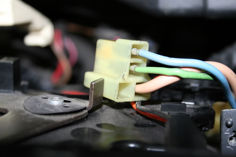
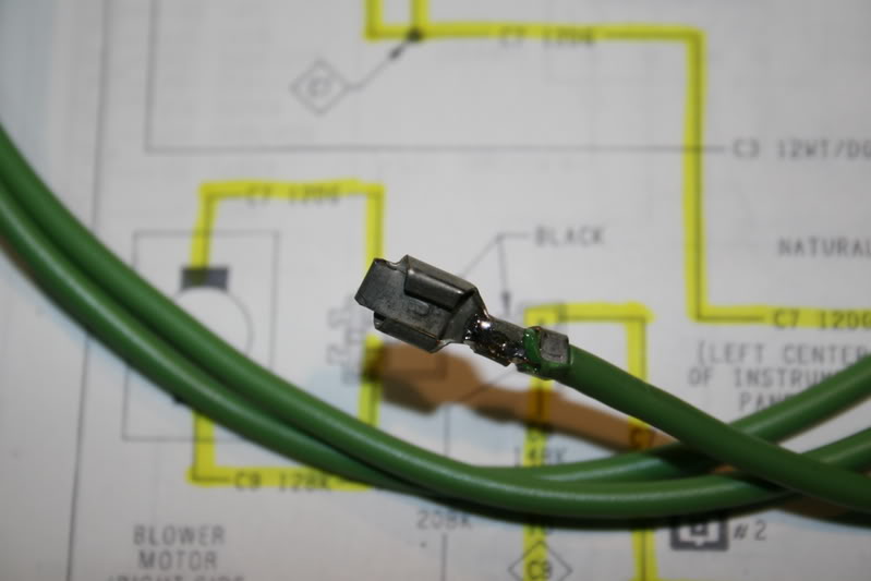
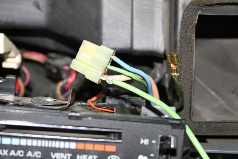
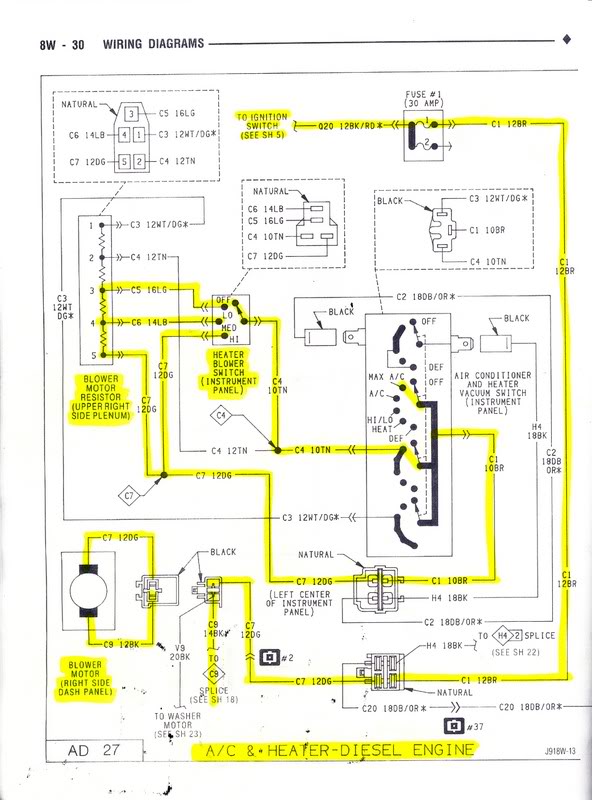
Using the wiring diagram later on in this post see the 2 wires connected to the blower motor, they should be Dark Green and Black.
Now with your engine running and the AC on MAX feel how much air is blowing AND listen how fast the motor is running.
Now carefully back probe the motor connector with the wires from your battery Negative to the BLACK and now touch the Positive wire to the DARK GREEN wire and see if the blower speeds up significantly.
If it does then you will benefit from this.
Back to my story,
As most of you know I have an air conditioner that will freeze you out of the cab on the hottest summer day but I have had a problem with the blower that seems to not be blowing as hard as I feel it should be, it seems like the performance had been slowly degrading to the point where it looks like it is time to find out why.
So armed with a wiring diagram I traced out the blower system and came up with a place to start, the blower.
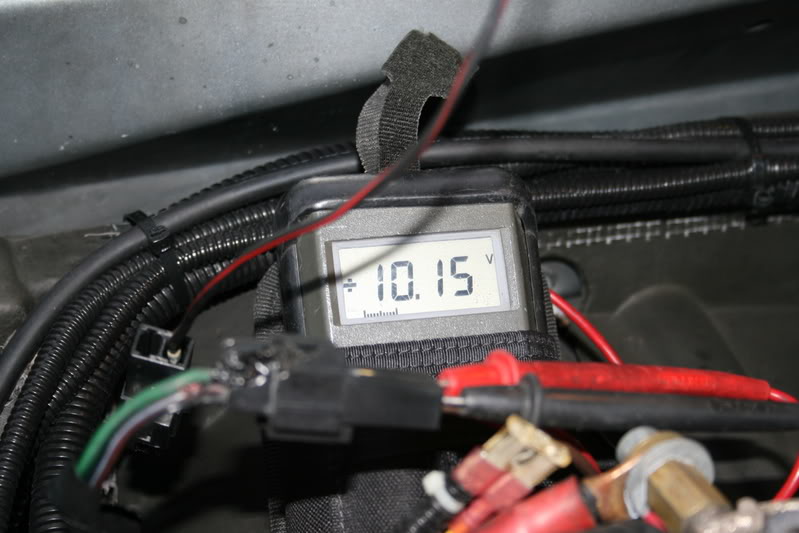
According to the diagram when the AC is on MAX and the speed is on Hi it should be receiving full battery voltage at the motor and as it goes from Med to Low it is put in series with the wirewound resistors in the air box to drop the current and voltage to the motor to give the motor a lower speed. (Not the way I would do it, I still might build a PWM speed controller), So armed with this information and my DVM I went to the motor and checked for a baseline. 10.15 volts and the motor was drawing 11.5 amps. So obviously there is some resistance somewhere that should not be there.
So we look�
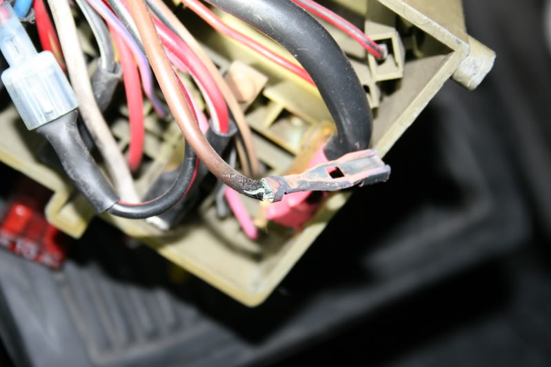
Starting at the fuse panel I found the fuse was melted and the panel was burned so here was the first problem I will need to repair.
Uhh yes, I have made a few modifications to my fuse panel to provide a few extra circuits.
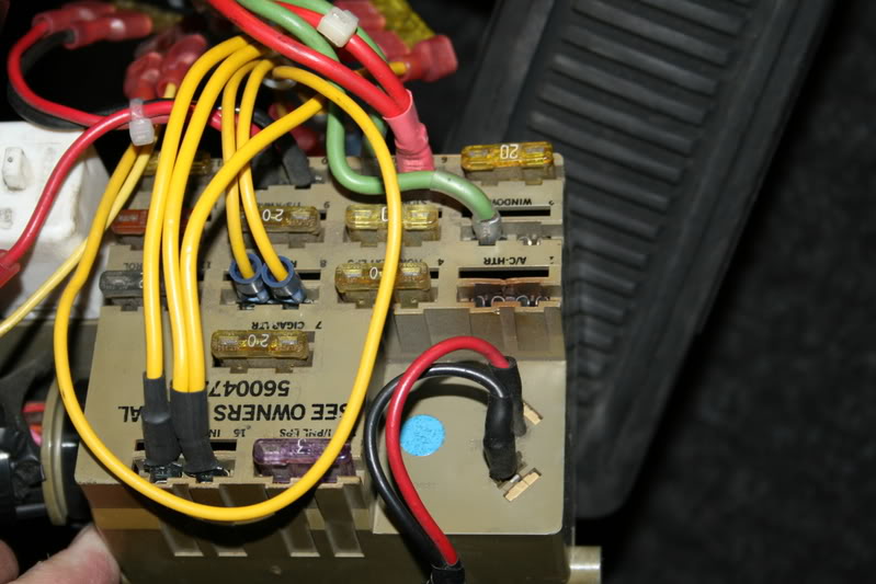
This was a genuine BUSS fuse and not a 50 assorted for $1.00 kind.
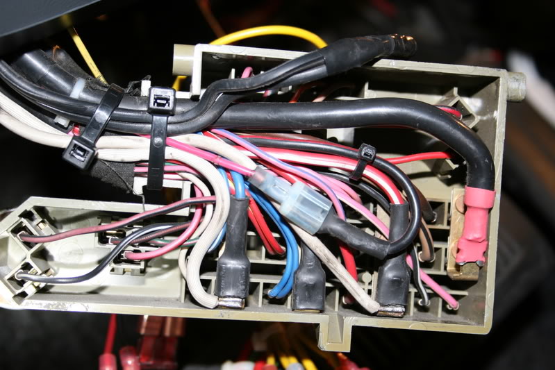
Here is the rear of the panel, you can see some of my modifications.
The heavy 6ga. wire on the right side for the AC/Power window circuit. was fed directly from the ignition switch, when I replaced my ignition switch after it burned up and melted the lower cover to the steering column I rerouted it through a relay and now the switch only carries the current of the relay. (I may do a write up on this procedure in the future; all of my fuse panel circuits are relay switched.)
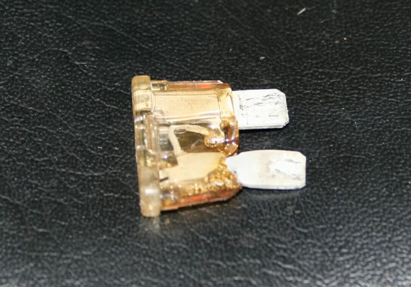
This is the terminal and wire that burned inside the fuse panel. It was a Brown 12ga. wire FYI
So if you know anything about me by now I will have to make it better and of course it will have something to do with a relay.
But first I will have to get that wire out of the fuse panel to where it can be managed.
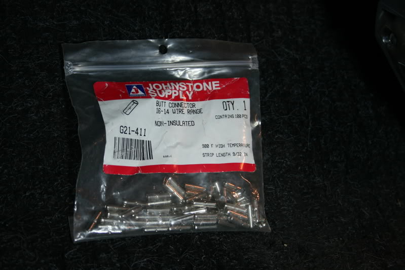
To make all of my splices I will be using these butt connectors, not just any but these are High Temperature Connectors. They are used in appliance repair and for HVAC work.
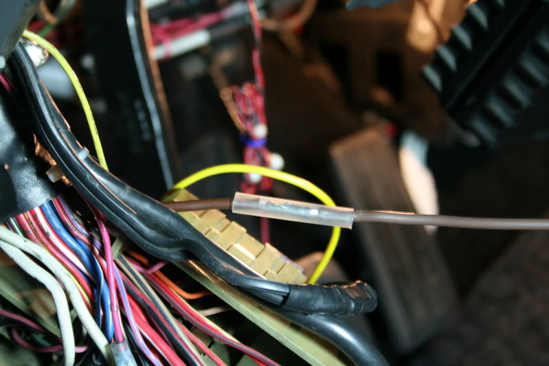
They are crimped using a pair of Sta-Kon pliers and a lot of muscle. I will also solder them and then heat shrink.
Here is the completed splice ready to be heated with a heat gun. It then will be routed back along the harness to another power feed where I have my relays mounted that switch the fuse panel.
You could alternately use a GOOD fuse holder and mount it externally; it will have to have at least a 10ga. wire for pigtails.
So in my quest to make it better what I have decided I am going to do is install a relay to handle all of the power for the blower while on HI and in the end I will get more air.
To do this I will need to make a few changes to the fan speed switch to accomplish my mission.
It sounds complicated right now but it is really easy if you follow what I do.
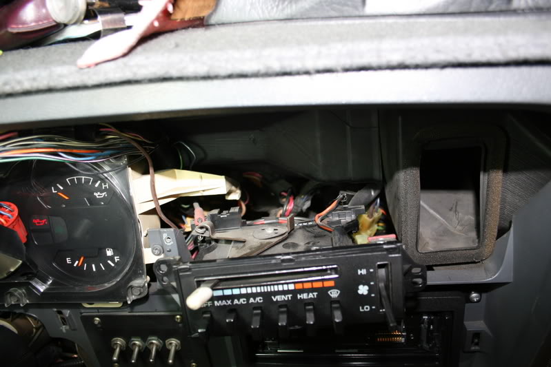
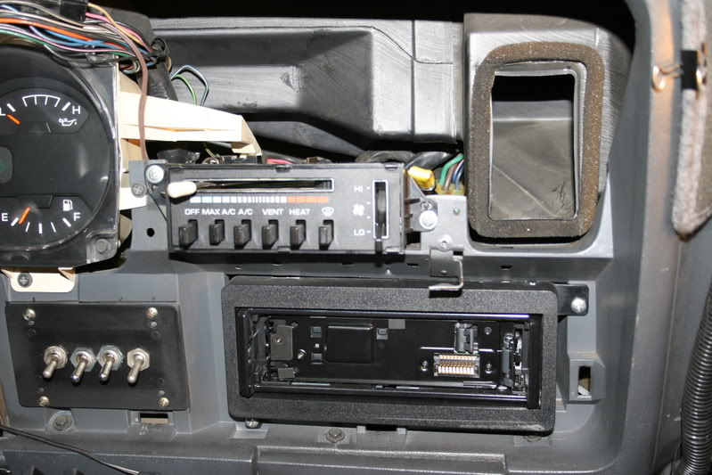
We need to remove all of the dash trim and have access to the connector on the back.
This fix will be for all of us with a 1st. Gen truck with the AC/Heater blower that does not blow enough air on Hi speed setting.
Getting a little ahead of myself, what I am going to do is to repair the wiring and install a set of relays to give the blower motor full available battery voltage and to regain effiency from this blower you never knew could be possible in your truck.
This might be hard to believe but this mod gave back the airflow and what feels like an extra speed. It now blows hard enough to mess up my hair and I have short hair.
To see if this will pertain to your truck there is a simple test you will need to perform, if you get the results I think you will then you will benefit greatly and should read on.
You will need 2 long jumper wires at least 12 ga. that will reach from your battery to your blower motor.
Using the wiring diagram later on in this post see the 2 wires connected to the blower motor, they should be Dark Green and Black.
Now with your engine running and the AC on MAX feel how much air is blowing AND listen how fast the motor is running.
Now carefully back probe the motor connector with the wires from your battery Negative to the BLACK and now touch the Positive wire to the DARK GREEN wire and see if the blower speeds up significantly.
If it does then you will benefit from this.
Back to my story,
As most of you know I have an air conditioner that will freeze you out of the cab on the hottest summer day but I have had a problem with the blower that seems to not be blowing as hard as I feel it should be, it seems like the performance had been slowly degrading to the point where it looks like it is time to find out why.
So armed with a wiring diagram I traced out the blower system and came up with a place to start, the blower.
According to the diagram when the AC is on MAX and the speed is on Hi it should be receiving full battery voltage at the motor and as it goes from Med to Low it is put in series with the wirewound resistors in the air box to drop the current and voltage to the motor to give the motor a lower speed. (Not the way I would do it, I still might build a PWM speed controller), So armed with this information and my DVM I went to the motor and checked for a baseline. 10.15 volts and the motor was drawing 11.5 amps. So obviously there is some resistance somewhere that should not be there.
So we look�
Starting at the fuse panel I found the fuse was melted and the panel was burned so here was the first problem I will need to repair.
Uhh yes, I have made a few modifications to my fuse panel to provide a few extra circuits.
This was a genuine BUSS fuse and not a 50 assorted for $1.00 kind.
Here is the rear of the panel, you can see some of my modifications.
The heavy 6ga. wire on the right side for the AC/Power window circuit. was fed directly from the ignition switch, when I replaced my ignition switch after it burned up and melted the lower cover to the steering column I rerouted it through a relay and now the switch only carries the current of the relay. (I may do a write up on this procedure in the future; all of my fuse panel circuits are relay switched.)
This is the terminal and wire that burned inside the fuse panel. It was a Brown 12ga. wire FYI
So if you know anything about me by now I will have to make it better and of course it will have something to do with a relay.
But first I will have to get that wire out of the fuse panel to where it can be managed.
To make all of my splices I will be using these butt connectors, not just any but these are High Temperature Connectors. They are used in appliance repair and for HVAC work.
They are crimped using a pair of Sta-Kon pliers and a lot of muscle. I will also solder them and then heat shrink.
Here is the completed splice ready to be heated with a heat gun. It then will be routed back along the harness to another power feed where I have my relays mounted that switch the fuse panel.
You could alternately use a GOOD fuse holder and mount it externally; it will have to have at least a 10ga. wire for pigtails.
So in my quest to make it better what I have decided I am going to do is install a relay to handle all of the power for the blower while on HI and in the end I will get more air.
To do this I will need to make a few changes to the fan speed switch to accomplish my mission.
It sounds complicated right now but it is really easy if you follow what I do.
We need to remove all of the dash trim and have access to the connector on the back.
Thread Starter
Administrator
Joined: Nov 2004
Posts: 4,084
Likes: 235
From: Southern California
Blower Motor Fix part-2
Now since I want to control the HI speed I will need to make a few changes at the switch at the connector.
Using a small screwdriver or pick carefully release the retainer to the DARK GREEN 12ga. wire and remove the connector from the housing.
You will want to insulate this and tuck it away; it will still have power even though it is disconnected.
Now using the same type of Packard connector crimp and solder it onto a length of 12ga. wire about 5 feet long (sorry I didn�t measure it first.)
Now replace the wire you had previously removed from the connector with the new one. It will only go it ONE way and lock so be careful.
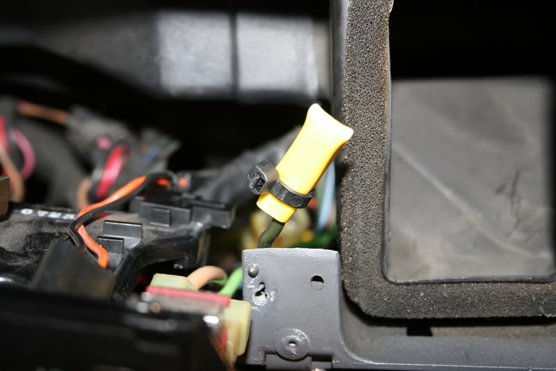
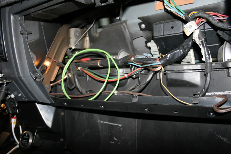
Now route the wire in with the old bundle and pass it into the right side dash behind the glove box (Remove the glove box first for more room.)
When looking at the AC control you want the wire to pass downward to the right side NOT up and over the air duct.
Here is how I insulated my wire and then tucked it out of the way.
Now reassemble the control into the dash and be careful that the left rear catches into the plastic clip, you will see what I mean when you are there.
Move the controls from COLD to HOT and be sure they are free, easier to fix a binding cable now than later.
Also be sure the vacuum connector is plugged in on the lower right of the panel.
Don�t ask me how I know about this.)
This is how the new wire should look coming out into the passenger side of the dash.
You will want to bundle this wire up with the rest of them and secure them into the clips.
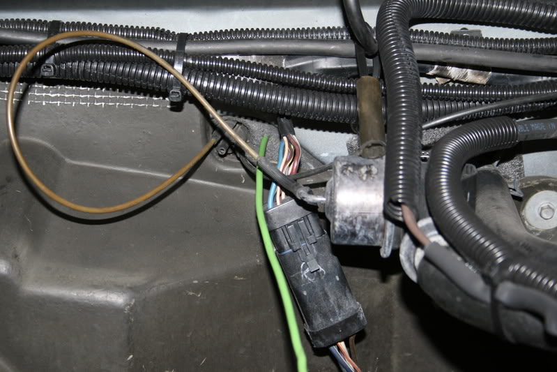
Now go into the engine compartment and look for the vacuum bulkhead connector
Where it enters into the cab.
Looking at the firewall and blower it is just left of the vacuum water valve.
Being very careful drill a 3/16� hole into the blower housing where I have done, be very careful that you do not snag and of the vacuum hoses with your big hands or the drill bitt.
You are only going through PLASTIC so be careful and only go in about �� when you feel it go through then STOP.
Then from the inside find the hole with a flashlight and then feed the new power wire out through the new hole into the engine compartment. Give yourself about 2 feet to work with.
Back on the inside route the wire out of the way of any of the moving parts of the servos and levers and secure them.
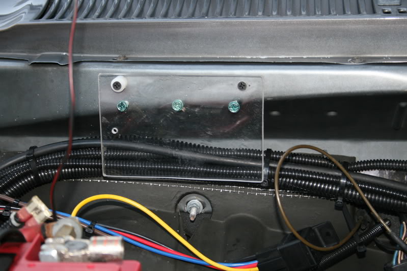
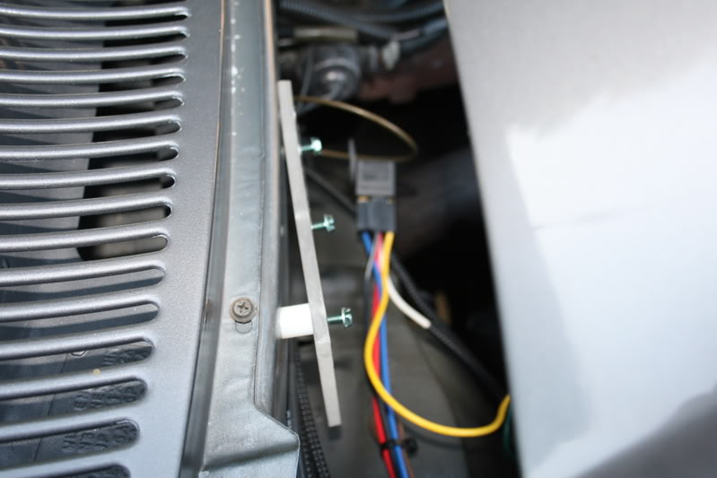
This is where I chose to mount my relays at least for now, I used a scrap of acrylic 4�X6�X1/4" and then drilled and tapped 3 mounting screws at 10X32 pitch.
To make up for the uneven surface of the firewall I cut a nylon spacer to fit the contour.
Now since I want to control the HI speed I will need to make a few changes at the switch at the connector.
Using a small screwdriver or pick carefully release the retainer to the DARK GREEN 12ga. wire and remove the connector from the housing.
You will want to insulate this and tuck it away; it will still have power even though it is disconnected.
Now using the same type of Packard connector crimp and solder it onto a length of 12ga. wire about 5 feet long (sorry I didn�t measure it first.)
Now replace the wire you had previously removed from the connector with the new one. It will only go it ONE way and lock so be careful.
Now route the wire in with the old bundle and pass it into the right side dash behind the glove box (Remove the glove box first for more room.)
When looking at the AC control you want the wire to pass downward to the right side NOT up and over the air duct.
Here is how I insulated my wire and then tucked it out of the way.
Now reassemble the control into the dash and be careful that the left rear catches into the plastic clip, you will see what I mean when you are there.
Move the controls from COLD to HOT and be sure they are free, easier to fix a binding cable now than later.
Also be sure the vacuum connector is plugged in on the lower right of the panel.
Don�t ask me how I know about this.)
This is how the new wire should look coming out into the passenger side of the dash.
You will want to bundle this wire up with the rest of them and secure them into the clips.
Now go into the engine compartment and look for the vacuum bulkhead connector
Where it enters into the cab.
Looking at the firewall and blower it is just left of the vacuum water valve.
Being very careful drill a 3/16� hole into the blower housing where I have done, be very careful that you do not snag and of the vacuum hoses with your big hands or the drill bitt.
You are only going through PLASTIC so be careful and only go in about �� when you feel it go through then STOP.
Then from the inside find the hole with a flashlight and then feed the new power wire out through the new hole into the engine compartment. Give yourself about 2 feet to work with.
Back on the inside route the wire out of the way of any of the moving parts of the servos and levers and secure them.
This is where I chose to mount my relays at least for now, I used a scrap of acrylic 4�X6�X1/4" and then drilled and tapped 3 mounting screws at 10X32 pitch.
To make up for the uneven surface of the firewall I cut a nylon spacer to fit the contour.
Thread Starter
Administrator
Joined: Nov 2004
Posts: 4,084
Likes: 235
From: Southern California
Blower Motor Fix part-3
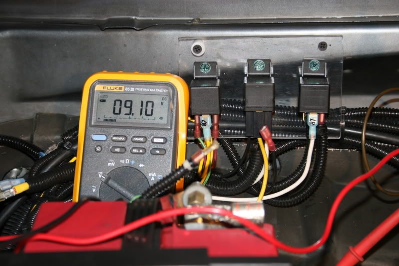
Ok now here is a top view of the mounting bracket looking down from the open hood.
I was looking for a piece of aluminum to make it but I had this handy and besides it lets me see the wiring behind it.
Now I am getting ahead of myself again, it is already wired up. Looking at the relays the one on the left is for the compressor clutch from my AC cycling switch post, the one in the center is the blower motor control >K-2< that actually switches the full battery power to the motor windings. And the one on the right is >K-1< for anti feedback to control the power relay.
Because of the way the blower is connected through the speed switch once the motor is running and the power is disconnected the motor is now a generator and it will feedback through the speed control resistor and hold the relay ON, this relay in needed to break the coil circuit and stop the blower.
Once again it sounds complicated but I have it all figured out for you.
Trust me..
The voltage you are looking at 9.10 VDC is the voltage the blower motor in now receiving with the speed switch on HI (actually MED speed) but going through the original path from Dodge without the full power relay engaged. I did this for a comparison to see how much resistance there still is in the factory wiring.
There are about 15 feet of 12ga. wire and a few feet of 10ga. wire in addition to about 4 connectors it has to take to get to this motor.
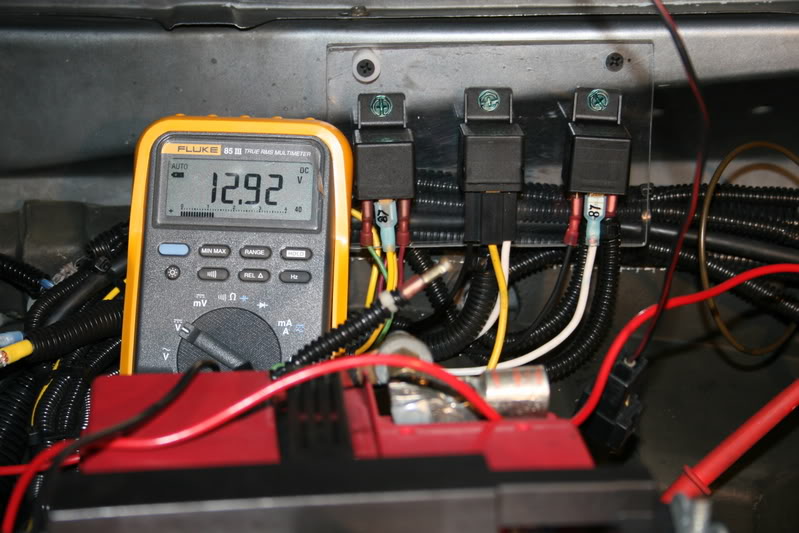
In this picture you can see how much voltage the blower motor is receiving with my full power relay engaged in the now normal operation mode.
That is 12.92 volts AT the motor connection, this is with the truck idling, and AC on MAX, the battery was at 13.0 volts.
The blower is now almost twice as fast as it was before going by the sound it was making.
A check with an ammeter shows the motor is now consuming 16.0 amps, which is UP from 11.5 amps that I got before I made any repairs.
So I can see the motor IS running a lot faster and harder than it was before.
But the true test, step into the cab and feel the air.. It is blowing hard like I have never felt it before.
My impression is that now I have to turn it down to MED and at this speed it is blowing as hard as it used to on HI.
This is the original wiring diagram I used, it is for a 91.5 so you might need to adjust accordingly for later vehicles.
I made only 3 connections to the factory wiring,
First one was the new wire you connected at the blower switch,
Second is the power at the blower motor and
Third is to provide the motor with a better ground although I got all of my gains without it.
All of my new circuit you will see on the left of the drawing, it is really simple.
Shopping List:
2) Standard 30 amp ISO Bosch relays,
2) 1 amp or better 1n4001 diodes (quench diode) observe the polarity band
12ga. automotive wire.
10ga. automotive wire.
Assorted terminals.
30 amp fuse and holder.
** Relay socket for K-2 (I got one from my local heavy truck parts, it has 10ga. wire pigtails and not 16ga. if you do not get one please wire it accordingly to handle minimum 30 amps.)
For your information, on the left of the drawing,
� �To switched ignition� can go to any terminal on your fuse block that has power when the key is �ON� Alternately you could connect this to your Fuel Solenoid terminal.
� �To Battery Terminal� you will want to connect to tour battery through either a 30-amp fuse or a 30-amp circuit breaker.
� I made the connections to the motor temporarily using heavy butt connectors because I need to replace the connector that mysteriously melted on my down pipe.
� You could also use small split bolt connectors you could get from Home Depot Electrical Dept.
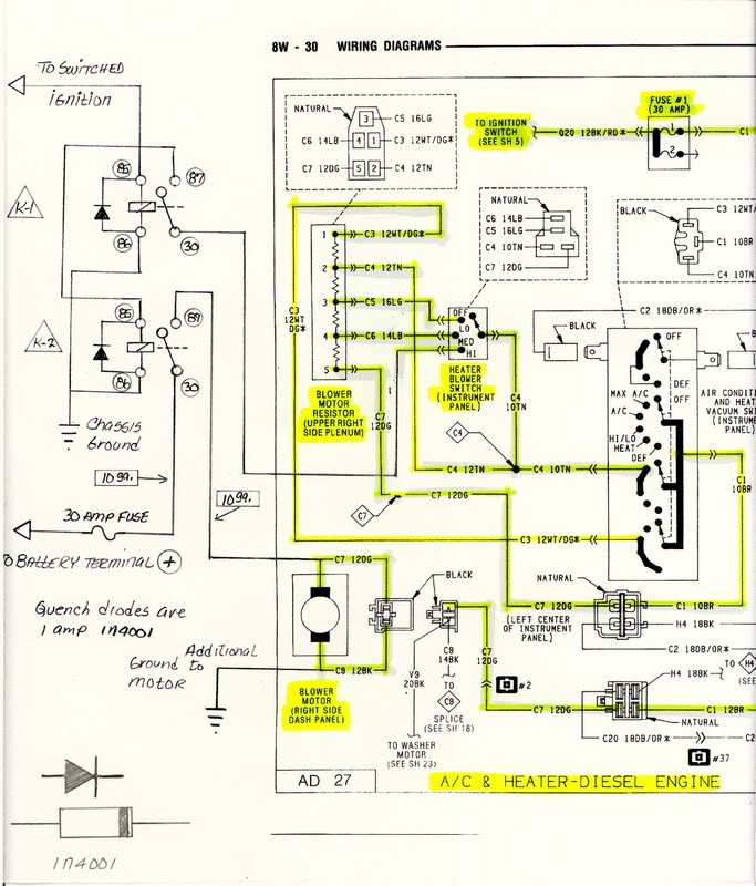
Here is a copy of the untouched original diagram; the mod is at the Heater Blower Switch (HI).
I just put this here for a reference.
I am really satisfied with the big improvement this has made to the performance of my air conditioner, It has been in the high 90* here for the last few days and I have been nice and cold in my truck and I now have air blowing in my face and man it is great.
Like I think I had mentioned, the old HI speed I now where the MED speed is and when it is on HI it feels like it has Turbo boost.
I hope this will help some of you out if you choose to take the test and see if you could benefit.
If you have any questions please ask.
Jim in HOT Southern California.
Ok now here is a top view of the mounting bracket looking down from the open hood.
I was looking for a piece of aluminum to make it but I had this handy and besides it lets me see the wiring behind it.
Now I am getting ahead of myself again, it is already wired up. Looking at the relays the one on the left is for the compressor clutch from my AC cycling switch post, the one in the center is the blower motor control >K-2< that actually switches the full battery power to the motor windings. And the one on the right is >K-1< for anti feedback to control the power relay.
Because of the way the blower is connected through the speed switch once the motor is running and the power is disconnected the motor is now a generator and it will feedback through the speed control resistor and hold the relay ON, this relay in needed to break the coil circuit and stop the blower.
Once again it sounds complicated but I have it all figured out for you.
Trust me..
The voltage you are looking at 9.10 VDC is the voltage the blower motor in now receiving with the speed switch on HI (actually MED speed) but going through the original path from Dodge without the full power relay engaged. I did this for a comparison to see how much resistance there still is in the factory wiring.
There are about 15 feet of 12ga. wire and a few feet of 10ga. wire in addition to about 4 connectors it has to take to get to this motor.
In this picture you can see how much voltage the blower motor is receiving with my full power relay engaged in the now normal operation mode.
That is 12.92 volts AT the motor connection, this is with the truck idling, and AC on MAX, the battery was at 13.0 volts.
The blower is now almost twice as fast as it was before going by the sound it was making.
A check with an ammeter shows the motor is now consuming 16.0 amps, which is UP from 11.5 amps that I got before I made any repairs.
So I can see the motor IS running a lot faster and harder than it was before.
But the true test, step into the cab and feel the air.. It is blowing hard like I have never felt it before.
My impression is that now I have to turn it down to MED and at this speed it is blowing as hard as it used to on HI.
This is the original wiring diagram I used, it is for a 91.5 so you might need to adjust accordingly for later vehicles.
I made only 3 connections to the factory wiring,
First one was the new wire you connected at the blower switch,
Second is the power at the blower motor and
Third is to provide the motor with a better ground although I got all of my gains without it.
All of my new circuit you will see on the left of the drawing, it is really simple.
Shopping List:
2) Standard 30 amp ISO Bosch relays,
2) 1 amp or better 1n4001 diodes (quench diode) observe the polarity band
12ga. automotive wire.
10ga. automotive wire.
Assorted terminals.
30 amp fuse and holder.
** Relay socket for K-2 (I got one from my local heavy truck parts, it has 10ga. wire pigtails and not 16ga. if you do not get one please wire it accordingly to handle minimum 30 amps.)
For your information, on the left of the drawing,
� �To switched ignition� can go to any terminal on your fuse block that has power when the key is �ON� Alternately you could connect this to your Fuel Solenoid terminal.
� �To Battery Terminal� you will want to connect to tour battery through either a 30-amp fuse or a 30-amp circuit breaker.
� I made the connections to the motor temporarily using heavy butt connectors because I need to replace the connector that mysteriously melted on my down pipe.
� You could also use small split bolt connectors you could get from Home Depot Electrical Dept.
Here is a copy of the untouched original diagram; the mod is at the Heater Blower Switch (HI).
I just put this here for a reference.
I am really satisfied with the big improvement this has made to the performance of my air conditioner, It has been in the high 90* here for the last few days and I have been nice and cold in my truck and I now have air blowing in my face and man it is great.
Like I think I had mentioned, the old HI speed I now where the MED speed is and when it is on HI it feels like it has Turbo boost.
I hope this will help some of you out if you choose to take the test and see if you could benefit.
If you have any questions please ask.
Jim in HOT Southern California.

Registered User
Joined: Nov 2006
Posts: 558
Likes: 1
nice job ,i wired mine with a relay and extra swich,we need more extra swiches in old dodges i see you you have your fare share, makes unbeliveable differance,also put extra wire and relay and switch to trailer running lights,wire goes from realy to trailer coupler.

Banned
Joined: Mar 2007
Posts: 278
Likes: 0
3 thumbs up for Jim_Lane!!  This guy is simply amazing with his ingenious, clean-looking installs/repairs, and provides some of the most clear and precise info/pics I've seen anywhere! I'm just speechless(yeah, like THAT will ever happen...). Many thanks, and a great job Jim, you should auction off copies of your works on ebay - I'd buy 'em!!
PS-(secret message to Wannadiesel, so nobody else should read this): I nominate Jim for the 'Best In Show' award for tech info!)
This guy is simply amazing with his ingenious, clean-looking installs/repairs, and provides some of the most clear and precise info/pics I've seen anywhere! I'm just speechless(yeah, like THAT will ever happen...). Many thanks, and a great job Jim, you should auction off copies of your works on ebay - I'd buy 'em!! PS-(secret message to Wannadiesel, so nobody else should read this): I nominate Jim for the 'Best In Show' award for tech info!)
Trending Topics
Adminstrator-ess
Joined: Mar 2003
Posts: 22,594
Likes: 19
From: New Holland, PA

Uh, I think if you post part 1 first it will be the first post. Not sure how you did what you did.
Great article, BTW.

Registered User
Joined: Jun 2003
Posts: 818
Likes: 0
From: Northern KS
Nice, need to try this on mine. My blower has always seemed kind of anemic.
So the latch relay drops out the power that triggers the second when you switch off the ignition. Will the fan back down off high speed ok once you switch it up there, or do you have to reset?
Andy
So the latch relay drops out the power that triggers the second when you switch off the ignition. Will the fan back down off high speed ok once you switch it up there, or do you have to reset?
Andy


Registered User


Joined: Oct 2005
Posts: 6,457
Likes: 95
From: KENTUCKY
This is a timely article, as I have been considering how to best go about this on our trucks.
I, too, on the son's truck, found the heater/blower fuse burnt and melted.
Thanks for sharing this with us.
I, too, on the son's truck, found the heater/blower fuse burnt and melted.
Thanks for sharing this with us.
Thread Starter
Administrator
Joined: Nov 2004
Posts: 4,084
Likes: 235
From: Southern California
Nice, need to try this on mine. My blower has always seemed kind of anemic.
So the latch relay drops out the power that triggers the second when you switch off the ignition. Will the fan back down off high speed ok once you switch it up there, or do you have to reset?
Andy
So the latch relay drops out the power that triggers the second when you switch off the ignition. Will the fan back down off high speed ok once you switch it up there, or do you have to reset?
Andy
If you do not have the (latch relay) everything will work as planned except for when you turn off the ignition the blower will keep running at full speed because the motor is generating enough voltage being fed back through the resistor to keep the relay pulled in thus supplying it full power, you need to interrupt the circuit for just an instant to stop the cycle.
This was just easier and it is also a safeguard.
Jim
Thread Starter
Administrator
Joined: Nov 2004
Posts: 4,084
Likes: 235
From: Southern California

Registered User
Joined: Oct 2006
Posts: 472
Likes: 0
From: APEX,NC
Great write up Jim!!! I will need to try the test on my blower. I have two questions that relate to your write up. Would shutting off coolant to heater core help in the cooling process ( this is an old trucker trick i learned when i was still trucking) and if so where could you aquire such a valve ? Also would tinted windows also help cool the cab area? My truck is a crew cab and it gets very hot and humid in North Carolina. I noticed in the early morning my a/c cools great but later in the heat of the day it really struggles. Just some random thoughts!!