
Blower motor


Thread Starter
Administrator


Joined: Nov 2004
Posts: 4,084
Likes: 235
From: Southern California
Well once again today I am running trying to get caught up, this afternoon I am on my way to my son's house to pull the rear rotors from his 2005 Dodge Ram 1500 so I can finish the brake job which had absolutely nothing to do with this post, But I was crusing down the freeway and saying to myself Man it is cold in here! I really did say that.
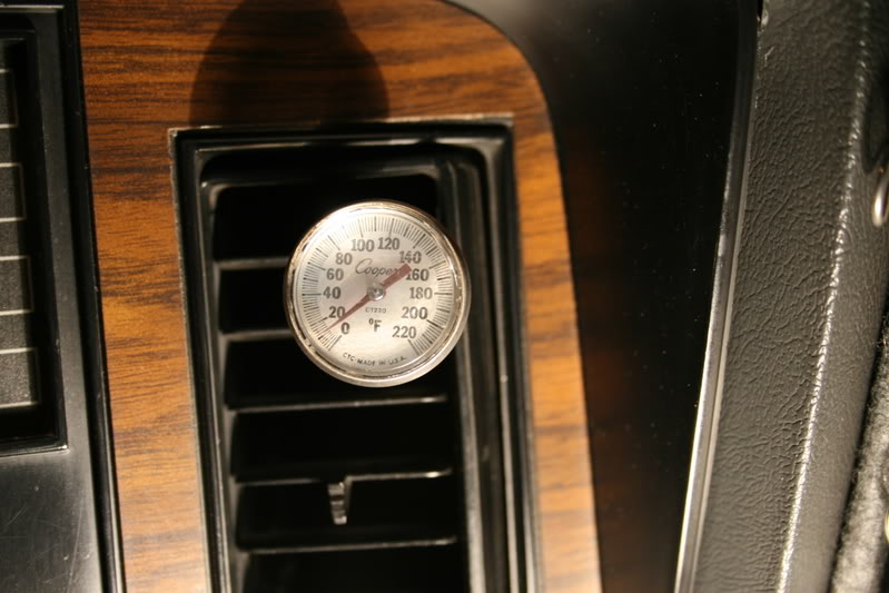
So I look at the thermometer stuck in the vent and guess what! Is really was cold. As I was getting on the freeway I past the bank and it was 86* outside and now the air coming from my vent is 15*.
That is 15* of knuckle freezing jack-frost nipping at your nose type cold air.
I had been wondering if after the modifications I had done to my blower motor and the big increase in airflow over the evaporator that I could still get my temps. as cold as before.
I can and I can�t see these temperatures I had the blower on MED-2 just under HI where as before I could get these temps with the blower on HI.
I turned the blower on HI and my temps went up to 20* but I guess I will have to live with that.
It is not easy trying to take a picture of a thermometer using a digital SLR while you are driving, that viewfinder is awfully small.
The increase in the airflow between MED-2 and HI I feel is almost double since I added the relay.
If I can figure out where I left my HVAC anemometer I could get an exact reading but for now I will guestimate.
Another factor of my cold air is the air flow over the condenser, I was traveling about 70 MPH for a few miles when it really started cooling good which is what I was saying about having an auxiliary condenser fan installed to supplement the low speed airflow you would experience in stop and go traffic.
Now I am not saying that my AC is always this cold because usually my around town driving keeps it around 35* and when I am alone I like to keep it freezing inside and put on a jacket but whenever my wife and daughter in the truck as soon as they see goose bumps on their arms or legs they start yelling to turn it down.
So I have to warm it up a bit.
I just thought I would share this with you.
Jim in Southern California
Registered User
Joined: Dec 2003
Posts: 1,518
Likes: 11
From: Boerne, TX
Great write up Jim!!! I will need to try the test on my blower. I have two questions that relate to your write up. Would shutting off coolant to heater core help in the cooling process ( this is an old trucker trick i learned when i was still trucking) and if so where could you aquire such a valve ? Also would tinted windows also help cool the cab area? My truck is a crew cab and it gets very hot and humid in North Carolina. I noticed in the early morning my a/c cools great but later in the heat of the day it really struggles. Just some random thoughts!!
http://www.4s.com/4sCat/PartImage.as...arts\74779.jpg
that link is for a valve for a 91 dodge shadow but many of Ma`s products use the same/similar valve, heres an ebay auction for a jeep valve (looks the same as the 4seasons part)
http://cgi.ebay.com/ebaymotors/JEEP-...QQcmdZViewItem

Registered User
Joined: Oct 2006
Posts: 472
Likes: 0
From: APEX,NC
Jim, yes i have the ve pump. My brakes seem OK! they don't seem to stop as well as they did before i did the conversion. I will try and do a vac check this weekend. Back on the subject of the A/C i installed the shut off valve and what a big difference. It was about 95/97 deg. today and i went for a short drive and the air actually worked much better than before. Next i will do the fan speed repair and i should be able to hang beef in the cab. LOL!!!
Thread Starter
Administrator
Joined: Nov 2004
Posts: 4,084
Likes: 235
From: Southern California
Jim, yes i have the ve pump. My brakes seem OK! they don't seem to stop as well as they did before i did the conversion. I will try and do a vac check this weekend. Back on the subject of the A/C i installed the shut off valve and what a big difference. It was about 95/97 deg. today and i went for a short drive and the air actually worked much better than before. Next i will do the fan speed repair and i should be able to hang beef in the cab. LOL!!!My brakes seem OK! they don't seem to stop as well as they did before i did the conversion.
How are your brakes not as good as before?
Whichever pump you have, if you do not have a sufficient supply of vacuum you will not have adequate power assist for your brakes, when you loose all of the power assist believe me it feels like you have a freight train pushing on your rear bumper and you will have to have both feet on the brake pedal to stop.
The vacuum for the inside controls is picked off the connection at the brake booster, where is crosses over the back of the engine they sometimes will get brittle and crack from the heat.
I have replaced mine with 1/8� nyflex air brake line the stuff that is used for your air shift valve on a semi tractor.
Tonight for some unknown reason I happen to turn on my defroster.
Man that thing can blow some air now, I had some papers on my dash and it blew them back at me and was lifting up the edge of my dash cover.
Jim
Registered User
Joined: Oct 2006
Posts: 472
Likes: 0
From: APEX,NC
Jim, I understand what you are talking about. My donor truck is a 91.5 w/ IC and the area you are refering to is right before the p/s pump. It is round in shape. I did not get a chance to check vac. today but will do it next week when we start installing new 47 rh trans. I shared your rewire for hi fan speed with McMopar and he was intrigued!!! He is getting ready to do 12v/p-pump conversion on a 74 crewcab. Beautiful truck will definetly be a sleeper when finished. The reason i don't think brakes stop as well as before is due to the weight of 12-v and the sorry brakes on the 1st. gen trucks. I have all new rotors and pads installed when i did upgrade on front axle. 3400 to 4000 lb. axle. When i do rear i am updating wheel cyl. to chevy and am thinking of hydro boost hmmmmmm! Augie
Banned
Joined: Dec 2005
Posts: 95
Likes: 0
From: sacto,ca
thanks for the info !! but HELP ?
very good info ! > & thanks for taking the time to write up !!
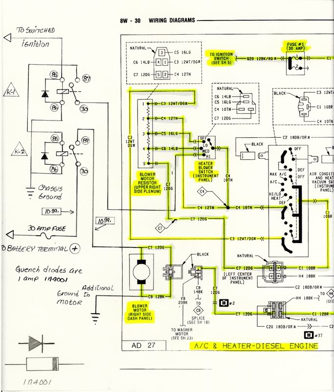
I was following that green wire very well , until IT went threw the fire wall ?
and then? help !! why, and how to wire a dioe ? any pics of your relay wireing ? dioe ?? why 3 relays ? or how about selling me some more do it yourself info with a more basic diagram ? I know I"m asking a lot !
so any more help is very much apperciated ,
once again thanks for the info !! NEEDS TO BE A STICKIE !!
Banned
Joined: Sep 2004
Posts: 1,278
Likes: 2
From: Christiana,Pa
Thread Starter
Administrator
Joined: Nov 2004
Posts: 4,084
Likes: 235
From: Southern California
very good info ! > & thanks for taking the time to write up !!
I was following that green wire very well , until IT went threw the fire wall ?
and then? help !! why, and how to wire a dioe ? any pics of your relay wireing ? dioe ?? why 3 relays ? or how about selling me some more do it yourself info with a more basic diagram ? I know I"m asking a lot !
so any more help is very much apperciated ,
once again thanks for the info !! NEEDS TO BE A STICKIE !!
Ok now some of you might have been following my schematic and got all confused about what the diode is in the circuit how it can be connected and what the heck it is there for.
First of all I will keep it simple.
Whenever you have a coil of wire around a core and you connect a voltage to it you will have an electromagnet where in our case the pole piece is shifted and makes or breaks the contacts in a relay.
But when you disconnect the voltage from the coil, the magnetic field collapses and creates a voltage or spike back into the circuit many times the input voltage, in the hundreds of volts which can damage the sensitive electronics (ECM�s) used newer vehicles.
The diode is placed in parallel to the coil to quench or absorb the spike so it does not get induced back into the circuits.
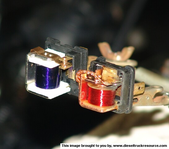
This shows one of the easy ways I use to mount a diode to the coil terminals onto an ISO relay; these particular ones are both Bosch. All you have to do is to carefully crimp the diode leads in the same terminal with the signal and ground wire.
This is very important, the BAND on the body of the diode is called the Cathode and must be on the wire that goes to the POSATIVE while the other lead which is called the Anode and will go the Ground side.
It does not matter which lead you switch but the polarity must be correct.
A diode is like a check valve and only flows in one direction but unlike a liquid line if you connect it ACROSS a battery wrong it will explode.
Please do not let that scare you, just remember the BAND goes to the hot side and you will be fine.
Also that diode looks big because it is a 4-amp diode, you only need to use a 1-amp and they are about � its size.
I also wire the diode into the wiring harness when I build some circuits or wire it right into a relay socket.
You can also get Bosch relays with an internal diode or with a resistor for the same purpose where you MUST observe the polarity.
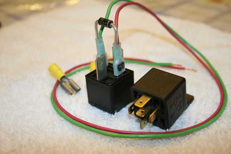
This is the same relay but at a different angle, if you will notice the size of terminals #30 and #87 you will see that they are 3/8� spade terminals opposed to the small �� terminals on the standard 30-amp relay on the right, that is because the one on the left is rated at 70-amps.
You will also notice that I write the terminal number on the female connector with a Sharpie pen so if they get disconnected it will be easy to reconnect to the proper terminal.
This is back to my original schematic or diagram, the circuit is really quite simple and if you do not feel comfortable wiring in the diodes then you can omit them completely if you like, the circuit will still work the same, it was just a safeguard I had put in.
You could also insert a small fuse of about 1 to 7 1/2 amps into the trigger circuit to protect the wiring in the event the coil ever shorted out but it is not necessary.

The relay on the far left controls the compressor clutch and it is covered in my A/C Cycling Switch article.
Click here to see this article.
https://www.dieseltruckresource.com/...d.php?t=112028
Back in the 70's I used to wire-wrap the motherboards on the Burroughs mainframes and Display Terminals, thousands of small mechanical connections with fine wire, then I would have to test the connections by toggling a switch and count out a bank of lights in binary.
I think if you tried to actually follow my wiring I would have totally confused but it is easier to follow my drawings.
I will have to post a picture of the underside of my dash. It is an array of pretty colors of spaghetti like wires going in all directions all neatly bundled and tied.
Scary part is only I know where they go to.
I hope this answered some of your questions.
Jim
Registered User
Joined: Jun 2007
Posts: 428
Likes: 0
From: Dallas Baby!!!!
You know, just last night I was talking to the wife and I said " there has got to be a way to get more air out of the blower motor" And here it is. I can't see any pics on your posts and I assume that is because I am at work. I will check again tonight when I get home.
I thought something was wrong with my truck because I never heard the A/C cycle. I am so used to Honda( Where I work). I think I will do an upgrade similar to yours. I will probably put a switch to cancel the blend door movement and wire a thermostat inline to the compressor coil. Having the compressor cycle may give me a little more mpg.
Thanks so much for posting this.
Leper
Banned
Joined: Dec 2005
Posts: 95
Likes: 0
From: sacto,ca
thanks
a ????? I think I"M getting it ?? could you please tell me about the connection on the blower motor , ( I"M sorry but I have not looked at it yet ) do I just splice into it ? or do i cut the wire & connect the 10 gauge wire to IT ?
what color is it ????? thanks a million
also is # 30 that new green wire ?
what color is it ????? thanks a million
also is # 30 that new green wire ?
Thread Starter
Administrator
Joined: Nov 2004
Posts: 4,084
Likes: 235
From: Southern California
a ????? I think I"M getting it ?? could you please tell me about the connection on the blower motor , ( I"M sorry but I have not looked at it yet ) do I just splice into it ? or do i cut the wire & connect the 10 gauge wire to IT ?
what color is it ????? thanks a million
also is # 30 that new green wire ?
what color is it ????? thanks a million
also is # 30 that new green wire ?
My blower motor has been replaced with a new motor a few years ago so I already had a connection there so what I did was to make a new splice using a high temperature inline uninsulated butt connector.
So the #10ga. wire that comes from terminal #87 on relay K-2 is spliced with the #12ga Dark-Green wire on the motor side of the 2 position connector. I made the connection there on the motor side so all of the new current is not going through the connector.
The way I made the connection was to use the 10ga. butt splice and insert the 10ga. wire in one side and crimp it and then I took the wire from the motor and the existing wire from the connector and inserted them in the opposite end with both wires together and crimped them, then I taped them using good Scotch-33 electrical tape.
Then take a ground wire and connect it to the Black wire coming from the blower motor in a similar fashion.
Watch the colors closely, the Dark-Green is the hot wire and the Black is the Ground.
also is # 30 that new green wire ?
Which green wire were you referring to?
On which relay K-1 or K-2?
Terminal #30 is the armature of the relay and toggles between both N.O. and N.C. and in most instances is the terminal the power is applied through, if you look at the schematic you will see that relay K-1 the terminal #30 gets its power from the Blower Motor switch and on relay K-2 the terminal #30 gets power directly from the battery through a 30 amp fuse or self resetting circuit breaker.

Thread Starter
Administrator
Joined: Nov 2004
Posts: 4,084
Likes: 235
From: Southern California
Here are some step-by-step instructions on how to connect up the 2 ISO relays used for my blower motor upgrade.
You can use any ISO relay however I would recommend you only use Genuine Bosch relays due to the high and continuous current they will need to handle.
Take 2 Bosch relays and label them K-1 and the other one K-2
K-1
Terminal identification number:
#30 connect this terminal to the blower switch HI terminal may use #14ga. wire.
#85 connect this terminal to the ignition switch, key/ON may use #16ga. or #14ga. wire also to the CATHODE on diode. (end with stripe on it.)
#86 connect this terminal along with the other relay #86 to ground lug may use #14ga. wire also to the ANODE end of diode.
#87 connect this terminal to terminal #85 on relay K-2, may use #14ga. wire.
K-2
Terminal identification number:
#30 connect this terminal to the battery (+) through a 30 amp fuse or a self-resetting Circuit Breaker, must use #10ga.wire.
#85 this terminal connects to terminal #87 on relay K-1, may use #14ga. wire, also to the CATHODE on diode. (end with stripe on it.)
#86 connect this terminal along with the other relay #86 to ground lug may use #14ga. wire also to the ANODE end of diode.
#87 this terminal connects to the to the new splice into the Dark-Green #14ga. wire at the blower motor, must use #10ga. wire.
How to identify a diode:
When you look at an axial diode you will see a lead protruding out of each end, at one of the ends you will see a Band or a LINE with the pointy end of an ARROW facing it, this end is the Cathode and will connect to the relay COIL terminal that goes to the (+)
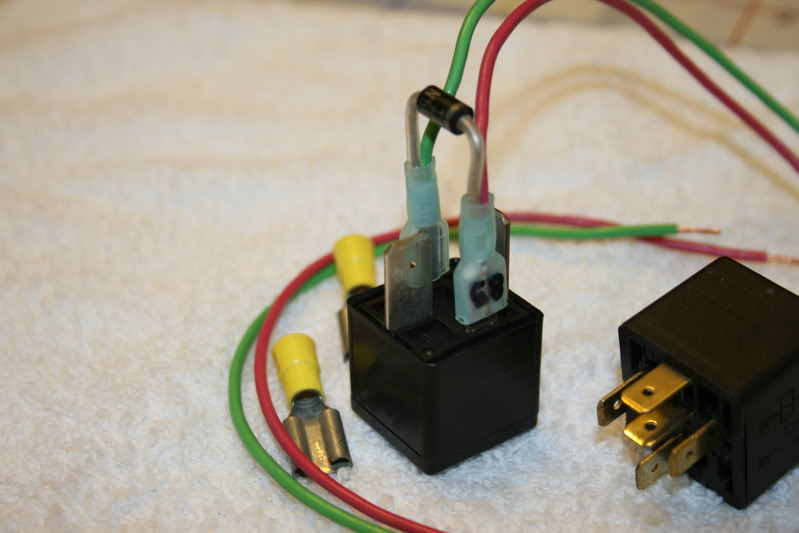
You can connect the Diode this way if you wish. Be aware that a Diode is fragile so be careful if you solder it in place, use a heat sink or grasp the lead with needle nose pliers to dissipate the heat away from the component.

Take a look at the difference between a Genuine Bosch and a cheap Generic look alike.
Bosch is on the left and Generic is on the right.
A thing about relays:
If you have an Auto Salvage Yard like a Pick-A-Part of self You �Grab-It type, check any of the better European cars like Mercedes, Volvo, Saab, VW they all use handfuls of Bosch relays and most of the Asian cars all have comparable relays used to control things like Fans, Fuel Pumps, Headlights, Horns.
If you use any of these relays, be sure to look at the side and verify the pinout numbers with the drawings. Some of the relays on the Asian cars I have seen the designations different than that of an ISO configuration.
These relays can be used for any of the circuits on our trucks and they will all have mating relay sockets. If the wiring is not long enough, most of them you can release the retainer clip and remove the wire from the back and then you can insert your own custom wires to your own configuration.
I hope this will make this modification a little easier to understand.
Jim
You can use any ISO relay however I would recommend you only use Genuine Bosch relays due to the high and continuous current they will need to handle.
Take 2 Bosch relays and label them K-1 and the other one K-2
K-1
Terminal identification number:
#30 connect this terminal to the blower switch HI terminal may use #14ga. wire.
#85 connect this terminal to the ignition switch, key/ON may use #16ga. or #14ga. wire also to the CATHODE on diode. (end with stripe on it.)
#86 connect this terminal along with the other relay #86 to ground lug may use #14ga. wire also to the ANODE end of diode.
#87 connect this terminal to terminal #85 on relay K-2, may use #14ga. wire.
K-2
Terminal identification number:
#30 connect this terminal to the battery (+) through a 30 amp fuse or a self-resetting Circuit Breaker, must use #10ga.wire.
#85 this terminal connects to terminal #87 on relay K-1, may use #14ga. wire, also to the CATHODE on diode. (end with stripe on it.)
#86 connect this terminal along with the other relay #86 to ground lug may use #14ga. wire also to the ANODE end of diode.
#87 this terminal connects to the to the new splice into the Dark-Green #14ga. wire at the blower motor, must use #10ga. wire.
How to identify a diode:
When you look at an axial diode you will see a lead protruding out of each end, at one of the ends you will see a Band or a LINE with the pointy end of an ARROW facing it, this end is the Cathode and will connect to the relay COIL terminal that goes to the (+)
You can connect the Diode this way if you wish. Be aware that a Diode is fragile so be careful if you solder it in place, use a heat sink or grasp the lead with needle nose pliers to dissipate the heat away from the component.
Take a look at the difference between a Genuine Bosch and a cheap Generic look alike.
Bosch is on the left and Generic is on the right.
A thing about relays:
If you have an Auto Salvage Yard like a Pick-A-Part of self You �Grab-It type, check any of the better European cars like Mercedes, Volvo, Saab, VW they all use handfuls of Bosch relays and most of the Asian cars all have comparable relays used to control things like Fans, Fuel Pumps, Headlights, Horns.
If you use any of these relays, be sure to look at the side and verify the pinout numbers with the drawings. Some of the relays on the Asian cars I have seen the designations different than that of an ISO configuration.
These relays can be used for any of the circuits on our trucks and they will all have mating relay sockets. If the wiring is not long enough, most of them you can release the retainer clip and remove the wire from the back and then you can insert your own custom wires to your own configuration.
I hope this will make this modification a little easier to understand.
Jim

Registered User
Joined: Oct 2006
Posts: 701
Likes: 1
From: Indianapolis, Indianna
Nothing, it did that stock too. ;-)
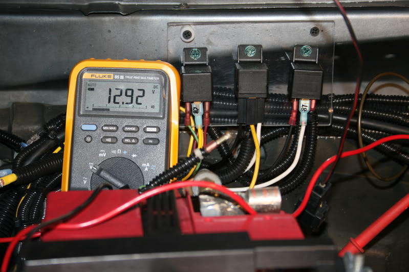
BTW. I did this to my truck & went from 10.00 v to 14.00 v with the engine running . . . . .but mine had bad splices from last time motor was replaced. .
BTW. I did this to my truck & went from 10.00 v to 14.00 v with the engine running . . . . .but mine had bad splices from last time motor was replaced. .