AC Cycling switch.
 08-08-2006, 06:44 AM
#1
Administrator
Thread Starter

Here are the instructions on how you can replace the electronic cycling switch that is used to control the AC clutch on your first generation Dodge trucks with a standard BOSCH or any ISO relay.
The cycling switch has a probe that is inserted into the suction line at the "H" valve and is used to throttle the compressor to prevent the evaporator from freezing.
When the small dip relay that is potted deep inside this module goes bad, your AC may either become erratic and stop working when you hit a bump and start working again when you perform the secret Mopar closed fisted rap on the dashboard.
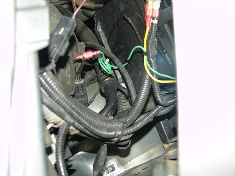
Here is where the connector is where the old inoperative cycling switch used to be connected to, I cut all 3 wires loose and you see we are only going to use the BLUE wire with the WHITE tracer. The BLUE and BROWN wire will not be used.
You should see the wires on yours more clearly; I have additional cables going to my linear accelerator.
FYI The BLUE/WHITE tracer wire has a switched ground signal.
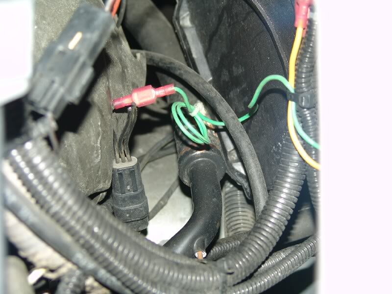
This is what will now be controlling the clutch of the compressor.
This is how I mounted mine but I was in a hurry when I designed this and I was in the middle of a Home Depot parking lot while on a road trip.
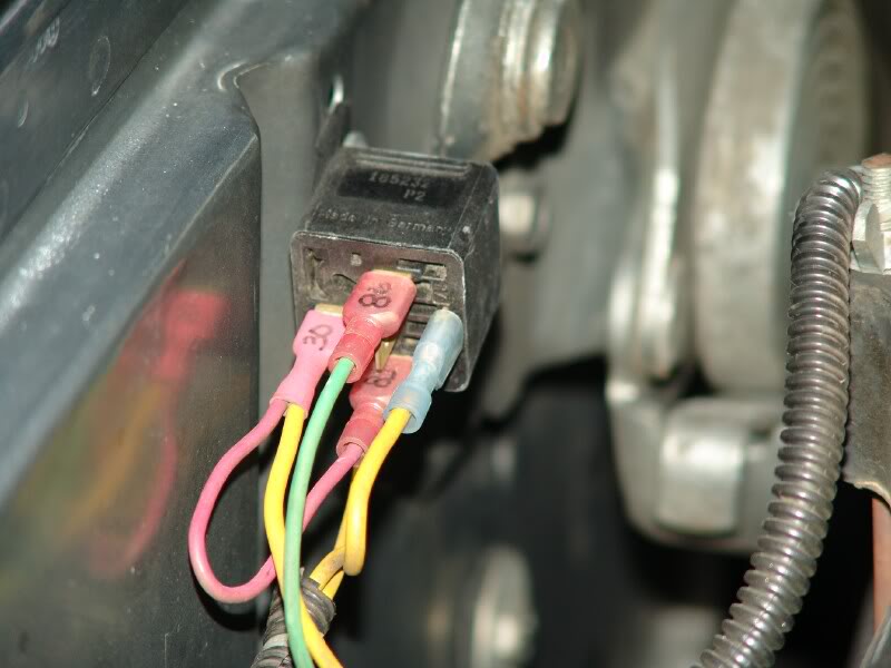
This is a better view of the install. See how I installed a small fuse inline using 2 female spade connectors? This works quite well for any application. I took the 12 VDC from my #2 auxiliary battery. I know I see the dirty battery..
The 1/2 X 9/19 wrench is the emergency battery wrench and is stuck to the fender panel by 2 rare earth magnets and is very hard to remove.
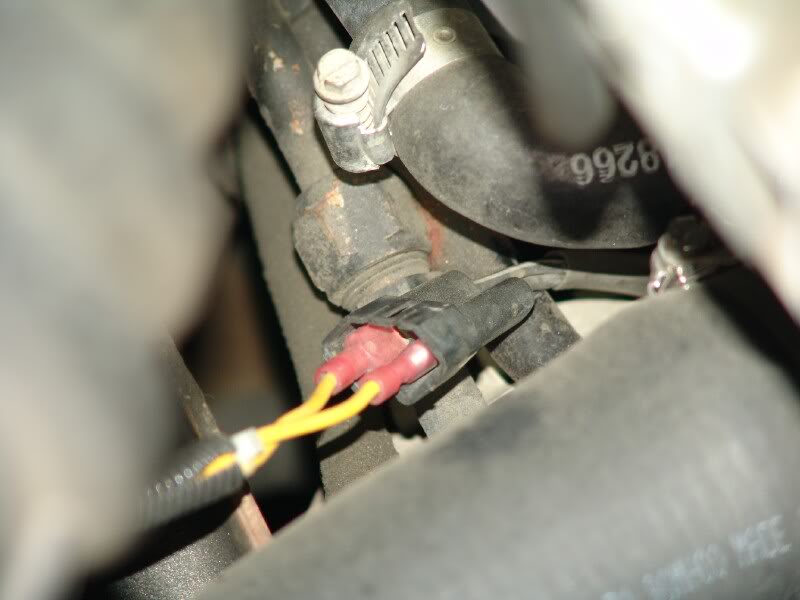
Here is the connection to the compressor clutch coil. I have the original harness tucked away so I can always revert back if needed or I come up with something new.
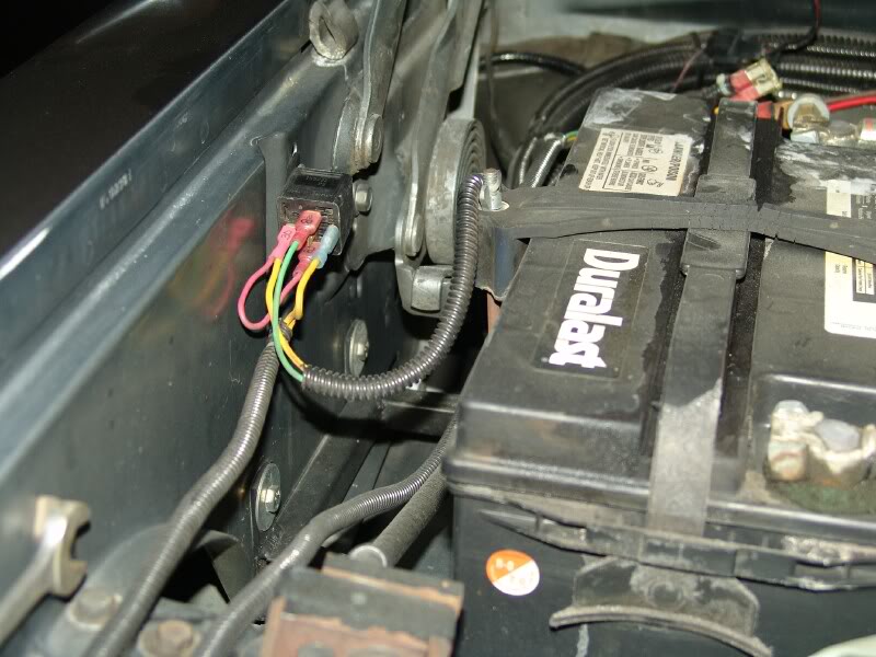
Here is a little wider shot behind my #2 battery showing the connector and the fuse.
You see at the end of the suction line there is a socket where the probe is inserted to monitor the temp.
BTW none of the wiring has been modified to the low-pressure cutout switch that is mounted to the "H" valve.
Very important... I have heard some say this Low Pressure cutout switch can be replaced and a new one installed, JUST UNSCREW IT...
NO NO NO there is no Schrader valve behind this and you will release all of your refergent before you could find the switch to put it back in.
I know GM's you can replace easily and maybe some of ours but I know for certain mine was NOT tapped for a Schrader.
Here is a simple line drawing of the entire setup,
Sorry I did not get around to draw it on my computer.
About the only change I would make to this design would be to install a diode across the relay coil to clamp the spike induced by the collapsing field.
Bosch also has a relay with one installed internally.
If you use one of these you have to pay particular attention to the polarity or it will be a dead short.
As I mentioned before, the downside to this setup is sometimes if the blower is on low speed, the evaporator can ice up and you will have to manually throttle the compressor to off until it thaws out.
Another downside is this makes my truck SOO uncomfortably cold inside I actually have to wear a jacket and everyone yells turn off the air, I�m cold.
Please go to Post #29 for a correction to this diagram.
NOTE. The "To Battery" goes to the Positive terminal
This should cost you around $6.00 if you are buying a genuine Bosch relay and maybe take about 1 hour.
I rate this as SIMPLE.
Let me know if you have any questions I can answer for you.
Jim in Southern California.
The cycling switch has a probe that is inserted into the suction line at the "H" valve and is used to throttle the compressor to prevent the evaporator from freezing.
When the small dip relay that is potted deep inside this module goes bad, your AC may either become erratic and stop working when you hit a bump and start working again when you perform the secret Mopar closed fisted rap on the dashboard.
Here is where the connector is where the old inoperative cycling switch used to be connected to, I cut all 3 wires loose and you see we are only going to use the BLUE wire with the WHITE tracer. The BLUE and BROWN wire will not be used.
You should see the wires on yours more clearly; I have additional cables going to my linear accelerator.
FYI The BLUE/WHITE tracer wire has a switched ground signal.
This is what will now be controlling the clutch of the compressor.
This is how I mounted mine but I was in a hurry when I designed this and I was in the middle of a Home Depot parking lot while on a road trip.
This is a better view of the install. See how I installed a small fuse inline using 2 female spade connectors? This works quite well for any application. I took the 12 VDC from my #2 auxiliary battery. I know I see the dirty battery..
The 1/2 X 9/19 wrench is the emergency battery wrench and is stuck to the fender panel by 2 rare earth magnets and is very hard to remove.
Here is the connection to the compressor clutch coil. I have the original harness tucked away so I can always revert back if needed or I come up with something new.
Here is a little wider shot behind my #2 battery showing the connector and the fuse.
You see at the end of the suction line there is a socket where the probe is inserted to monitor the temp.
BTW none of the wiring has been modified to the low-pressure cutout switch that is mounted to the "H" valve.
Very important... I have heard some say this Low Pressure cutout switch can be replaced and a new one installed, JUST UNSCREW IT...
NO NO NO there is no Schrader valve behind this and you will release all of your refergent before you could find the switch to put it back in.
I know GM's you can replace easily and maybe some of ours but I know for certain mine was NOT tapped for a Schrader.
Here is a simple line drawing of the entire setup,
Sorry I did not get around to draw it on my computer.
About the only change I would make to this design would be to install a diode across the relay coil to clamp the spike induced by the collapsing field.
Bosch also has a relay with one installed internally.
If you use one of these you have to pay particular attention to the polarity or it will be a dead short.
As I mentioned before, the downside to this setup is sometimes if the blower is on low speed, the evaporator can ice up and you will have to manually throttle the compressor to off until it thaws out.
Another downside is this makes my truck SOO uncomfortably cold inside I actually have to wear a jacket and everyone yells turn off the air, I�m cold.
Please go to Post #29 for a correction to this diagram.
NOTE. The "To Battery" goes to the Positive terminal
This should cost you around $6.00 if you are buying a genuine Bosch relay and maybe take about 1 hour.
I rate this as SIMPLE.
Let me know if you have any questions I can answer for you.
Jim in Southern California.
Last edited by Jim Lane; 08-03-2010 at 03:59 AM. Reason: Note about wiring diagram.
 08-08-2006, 07:38 AM
#2
Adminstrator-ess
This won't work exactly as shown on an intercooled truck because the PCM controls the A/C compressor. It can be done, but it's more involved. This afternoon I'll poke through my wiring diagrams and figure out an intercooled version.
08-08-2006, 08:50 AM
#3
Registered User

Join Date: Feb 2006
Location: Hartsville SC
Posts: 74
Likes: 0
Received 0 Likes
on
0 Posts
Jim & Wanna
These two posts, and their like, are what make this and awsome site, the people here . The knowledge is just scary
  .
.
My ac was full of leaves so I cleaned it out. Still got only 51 or 52 drgs., soooo, got to be the switch. $41.00 later and nothing has changed, still 51 deg.
I tried pulling the tip out in stages and nothing changed till it froze up.
By the way, mine is a 92LE EXT Cab.
I"m still trying to get over that 3200 gov spring .
.
Thanks Guys
[edit] It is not low on freon charge.
These two posts, and their like, are what make this and awsome site, the people here
. The knowledge is just scary .My ac was full of leaves so I cleaned it out. Still got only 51 or 52 drgs., soooo, got to be the switch. $41.00 later and nothing has changed, still 51 deg.
I tried pulling the tip out in stages and nothing changed till it froze up.
By the way, mine is a 92LE EXT Cab.
I"m still trying to get over that 3200 gov spring
.Thanks Guys
[edit] It is not low on freon charge.
08-09-2006, 05:34 PM
#5
Adminstrator-ess
Originally Posted by wannadiesel
This won't work exactly as shown on an intercooled truck because the PCM controls the A/C compressor. It can be done, but it's more involved. This afternoon I'll poke through my wiring diagrams and figure out an intercooled version.
 08-10-2006, 08:56 AM
#7
Registered User
Join Date: Oct 2002
Location: Windsor Ontario Canada
Posts: 356
Likes: 0
Received 0 Likes
on
0 Posts
Wrong relay wiring
Jim... Not trying to be smart, but the wiring on your relay is wrong.A relay or solenoid is used to allow a small load to control a large load.
It will work, but you're defeating the purpose of the relay by splicing #85 off #30.
They should actually be two separate feeds. #30 should be the battery (LOAD) circuit and #85 should only be the relay trigger circuit. #85 and #86 are the relay ON/OFF circuit. #30 is to supply power THROUGH the relay to #87 when the relay is turned on and #87a when the relay is turned off.
By separating the feeds on the relay, you won't be putting the load on the trigger circuit. The load will only be on the battery feed circuit #30 only. It also prevents #30 from backfeeding the trigger circuit #85 even when #85 trigger circuit is shut off.
Just for reference. #85 and #86 are reversable. It's just a coil. Either one can be positive or negative. Some people prefer to use #86 as the trigger, but that part doesn't really matter.
Nothing personal. Just correcting a very common mistake made by many.
Trending Topics
08-10-2006, 09:45 AM
#8
Registered User
Join Date: May 2004
Location: Golden, Colorado
Posts: 2,867
Likes: 0
Received 0 Likes
on
0 Posts
Originally Posted by Rammer64
Jim... Not trying to be smart, but the wiring on your relay is wrong.A relay or solenoid is used to allow a small load to control a large load.
It will work, but you're defeating the purpose of the relay by splicing #85 off #30.
They should actually be two separate feeds. #30 should be the battery (LOAD) circuit and #85 should only be the relay trigger circuit. #85 and #86 are the relay ON/OFF circuit. #30 is to supply power THROUGH the relay to #87 when the relay is turned on and #87a when the relay is turned off.
By separating the feeds on the relay, you won't be putting the load on the trigger circuit. The load will only be on the battery feed circuit #30 only. It also prevents #30 from backfeeding the trigger circuit #85 even when #85 trigger circuit is shut off.
Just for reference. #85 and #86 are reversable. It's just a coil. Either one can be positive or negative. Some people prefer to use #86 as the trigger, but that part doesn't really matter.
Nothing personal. Just correcting a very common mistake made by many.
It will work, but you're defeating the purpose of the relay by splicing #85 off #30.
They should actually be two separate feeds. #30 should be the battery (LOAD) circuit and #85 should only be the relay trigger circuit. #85 and #86 are the relay ON/OFF circuit. #30 is to supply power THROUGH the relay to #87 when the relay is turned on and #87a when the relay is turned off.
By separating the feeds on the relay, you won't be putting the load on the trigger circuit. The load will only be on the battery feed circuit #30 only. It also prevents #30 from backfeeding the trigger circuit #85 even when #85 trigger circuit is shut off.
Just for reference. #85 and #86 are reversable. It's just a coil. Either one can be positive or negative. Some people prefer to use #86 as the trigger, but that part doesn't really matter.
Nothing personal. Just correcting a very common mistake made by many.
08-11-2006, 05:29 AM
#9
Administrator
Thread Starter
Originally Posted by Rammer64
Jim... Not trying to be smart, but the wiring on your relay is wrong.A relay or solenoid is used to allow a small load to control a large load.
It will work, but you're defeating the purpose of the relay by splicing #85 off #30.
They should actually be two separate feeds. #30 should be the battery (LOAD) circuit and #85 should only be the relay trigger circuit. #85 and #86 are the relay ON/OFF circuit. #30 is to supply power THROUGH the relay to #87 when the relay is turned on and #87a when the relay is turned off.
By separating the feeds on the relay, you won't be putting the load on the trigger circuit. The load will only be on the battery feed circuit #30 only. It also prevents #30 from backfeeding the trigger circuit #85 even when #85 trigger circuit is shut off.
Just for reference. #85 and #86 are reversable. It's just a coil. Either one can be positive or negative. Some people prefer to use #86 as the trigger, but that part doesn't really matter.
Nothing personal. Just correcting a very common mistake made by many.
It will work, but you're defeating the purpose of the relay by splicing #85 off #30.
They should actually be two separate feeds. #30 should be the battery (LOAD) circuit and #85 should only be the relay trigger circuit. #85 and #86 are the relay ON/OFF circuit. #30 is to supply power THROUGH the relay to #87 when the relay is turned on and #87a when the relay is turned off.
By separating the feeds on the relay, you won't be putting the load on the trigger circuit. The load will only be on the battery feed circuit #30 only. It also prevents #30 from backfeeding the trigger circuit #85 even when #85 trigger circuit is shut off.
Just for reference. #85 and #86 are reversable. It's just a coil. Either one can be positive or negative. Some people prefer to use #86 as the trigger, but that part doesn't really matter.
Nothing personal. Just correcting a very common mistake made by many.
87a is the normally closed connection (can be used as a switched voltage output when the relay is at rest). (This terminal offers no voltage when the relay is energized.)
87 is the normally open connection (switched voltage output when the relay is energized).
85 is connected to the ground of the triggering voltage.
86 is connected to the positive 12V of the triggering voltage.
This circuit is exactly as I planed it, I will explain my logic.
#30 is the armature of the relay and transfers the voltage between
#87a NC contact and
#87 NO contact.
12 + from the battery is fed into the armature always to switch between the 2 states (NO) normally open or (NC) normally closed
(The only time you would connect it 87a & 87 LINE instead of LOAD is if you are switching 2 sources to 1 destination) which I have done numerous times.
#85 & 86 are the coil as you mentioned BUT do not assume they are always non polarized.
I also use a BOSCH 0 332-019-155 is a 40-amp relay that has a quench diode built in and therefore #86 is (+) and #85 (-)
http://www.chiefent.com/products/products_relays.asp
So #30 and #85 one leg of the coil are connected together and to the 12 volt positive through a fuse, now the coil has power always all I need to supply is a ground path which is supplied by the BLUE /white wire that used to control the cycling switch. When the AC control calls for cold, it sends a ground state to the BLUE/ white wire, it supplies the required ground to the coil and pulls the armature (C) to contact #87(NO) and since the battery is connected also to #30 #87 is now @ (+) 12 volts the same terminal the compressor clutch is supplied and is returned through its own ground wire.
#86 although usually connected to the (+) I connected it to the (-) to keep the circuits consistent with all of my other (+) switched relay circuits.
When the coil opens and the relay is de-energized since it is connected to the #87 (NO) the resulting spike (Back EMF) now has nowhere to go and is not connected electrically to the coil circuit.
I do have quench diodes (1N4003) installed in my circuits including the clutch coil (1N4004) but now I am getting too technical for probably 90% of the people who would read this and if they tried to duplicate this if it was not connected properly could burn up some of the wiring in their trucks.
I am making this simple and bulletproof as possible.
I also have some L/C & R/C timer circuits I have designed around relays but most people would not have a clue what I am talking about.
Quote
It will work, but you're defeating the purpose of the relay by splicing #85 off #30.
They should actually be two separate feeds. #30 should be the battery (LOAD) circuit and #85 should only be the relay trigger circuit. #85 and #86 are the relay ON/OFF circuit. #30 is to supply power THROUGH the relay to #87 when the relay is turned on and #87a when the relay is turned off.
By separating the feeds on the relay, you won't be putting the load on the trigger circuit. The load will only be on the battery feed circuit #30 only. It also prevents #30 from backfeeding the trigger circuit #85 even when #85 trigger circuit is shut off.
I do not understand why I would want 2 (+) feeds to #30 & #85 when they are going to the same source. I want the coil to always have power because I am switching the ground.
Or am I missing something here.
Jim
08-11-2006, 05:39 AM
#10
Banned

Join Date: Feb 2005
Posts: 341
Likes: 0
Received 0 Likes
on
0 Posts
I can't take anymore, I have to ask .......... WHY?
If the AC is charged properly you don't need ANY "modifications"
I must have missed something is AC class 30 years ago since my AC
pops 36* out of the vents and cycles like it was designed to do.
BTW, the pressure switch also keeps the high side from running wild by
cycling the compressor until the low side pressure rises.
59
08-11-2006, 06:34 AM
#11
Administrator
Thread Starter
Originally Posted by 59FORD
I can't take anymore, I have to ask .......... WHY?
If the AC is charged properly you don't need ANY "modifications"
I must have missed something is AC class 30 years ago since my AC
pops 36* out of the vents and cycles like it was designed to do.
59
If the AC is charged properly you don't need ANY "modifications"
I must have missed something is AC class 30 years ago since my AC
pops 36* out of the vents and cycles like it was designed to do.
59
The modification to replace the cycling switch has nothing to do with improving the performance of the air conditioner.
It is only to replace a part of the control circuitry that Dodge Chrysler has put on the system to throttle the compressor clutch to prevent the evaporator from icing up probably on low airflow conditions.
When this part fails it becomes intermittent and most people don�t even know it exist when the compressor won�t run, and is a simple fix to replace a $40.00 part.
The downside of this fix is in the event it does ice up then you just have to manually turn off the AC and let it defrost for a minute.
Also because it is not cycling the compressor when it is getting to the freeze point, the evaporator gets colder.
My air conditioner actually gets uncomfortably cold where you have to turn it up or put on a jacket.
Yesterday it was 105* here in SB County and driving home it was so cold in the cab my daughter and wife were covered up and the foot vents were freezing our feet.
Register temps are usually around 30* with the blower on high.
It is also more efficient because I pulled the interior of the cab and have 5/8 foam foil backed insulation on the floorboard and back of the cab and 5/8 foam carpet padding on top of that. Then the padded carpet went back down on top of that.
My aim was to make the cab quieter but this was an added bonus.
I do not advocate that this will make the AC colder, it is sometimes a bonus.
What kind of AC�s did you used to work on?
I worked on units in transit busses that were powered by 4 cylinder Perkins diesels driving a 5 cylinder Trane compressors tucked underneath or they had a V-drive off the drive engine.
These required 75- 100 HP just to power the AC and took 30 to 50 pounds of R-22.
They had A-coil style evaporators that were about 7� wide X 24� high.
The super chilled air had to be tempered going through air/ liquid exchangers with the engine coolant or you would freeze the passengers solid within minuets.
Brings back a lot of memories.
Jim
08-11-2006, 08:03 AM
#12
Registered User
Join Date: Feb 2006
Location: Hartsville SC
Posts: 74
Likes: 0
Received 0 Likes
on
0 Posts
OK Jim.
Guess i'll chase my tail for a little while .
I was under the impression that this mod would lower the vent temps by keeping the comperssor running longer but not to freese up, well most of the time.
My system is runnin' fine except for the vent temps which are 50 dgr. at best .
If this don't improve things then I'll do the $31 heater bypass valve from NAPA.
I'll still have the parts in my truck for when the switch does fail, hummmm, got two switches already, guess three will work too.
I'm giong to try this this weekend and will post again. It's cheaper than the bypass valve.
GW
Guess i'll chase my tail for a little while
.I was under the impression that this mod would lower the vent temps by keeping the comperssor running longer but not to freese up, well most of the time.
My system is runnin' fine except for the vent temps which are 50 dgr. at best
.If this don't improve things then I'll do the $31 heater bypass valve from NAPA.
I'll still have the parts in my truck for when the switch does fail, hummmm, got two switches already, guess three will work too.
I'm giong to try this this weekend and will post again. It's cheaper than the bypass valve.
GW
08-11-2006, 11:14 AM
#13
Registered User
Join Date: Oct 2002
Location: Windsor Ontario Canada
Posts: 356
Likes: 0
Received 0 Likes
on
0 Posts
Originally Posted by Jim Lane
#30 is the armature of the relay and transfers the voltage between
#87a NC contact and
#87 NO contact.
12 + from the battery is fed into the armature always to switch between the 2 states (NO) normally open or (NC) normally closed
(The only time you would connect it 87a & 87 LINE instead of LOAD is if you are switching 2 sources to 1 destination) which I have done numerous times.
#85 & 86 are the coil as you mentioned BUT do not assume they are always non polarized.
I also use a BOSCH 0 332-019-155 is a 40-amp relay that has a quench diode built in and therefore #86 is (+) and #85 (-)
http://www.chiefent.com/products/products_relays.asp
So #30 and #85 one leg of the coil are connected together and to the 12 volt positive through a fuse, now the coil has power always all I need to supply is a ground path which is supplied by the BLUE /white wire that used to control the cycling switch. When the AC control calls for cold, it sends a ground state to the BLUE/ white wire, it supplies the required ground to the coil and pulls the armature (C) to contact #87(NO) and since the battery is connected also to #30 #87 is now @ (+) 12 volts the same terminal the compressor clutch is supplied and is returned through its own ground wire.
#86 although usually connected to the (+) I connected it to the (-) to keep the circuits consistent with all of my other (+) switched relay circuits.
When the coil opens and the relay is de-energized since it is connected to the #87 (NO) the resulting spike (Back EMF) now has nowhere to go and is not connected electrically to the coil circuit.
I do have quench diodes (1N4003) installed in my circuits including the clutch coil (1N4004) but now I am getting too technical for probably 90% of the people who would read this and if they tried to duplicate this if it was not connected properly could burn up some of the wiring in their trucks.
I am making this simple and bulletproof as possible.
I also have some L/C & R/C timer circuits I have designed around relays but most people would not have a clue what I am talking about.
Quote
It will work, but you're defeating the purpose of the relay by splicing #85 off #30.
They should actually be two separate feeds. #30 should be the battery (LOAD) circuit and #85 should only be the relay trigger circuit. #85 and #86 are the relay ON/OFF circuit. #30 is to supply power THROUGH the relay to #87 when the relay is turned on and #87a when the relay is turned off.
By separating the feeds on the relay, you won't be putting the load on the trigger circuit. The load will only be on the battery feed circuit #30 only. It also prevents #30 from backfeeding the trigger circuit #85 even when #85 trigger circuit is shut off.
I do not understand why I would want 2 (+) feeds to #30 & #85 when they are going to the same source. I want the coil to always have power because I am switching the ground.
Or am I missing something here.
Jim
I referred to the use of #85 as the + trigger for energizing the relay through a switch and #86 (relay ground circuit) being constant ground.
A quick example would be a starter solenoid. If you notice the trigger wire to energize the solenoid is relatively small compared to the battery terminal wires. Relays and solenoids serve the same purpose. Relays and solenoids use a small amount of current to control a large amount of current. They design the circuits using solenoids/relays with two separate feeds because if you were to connect the ignition switch wire directly to the starter, the load (AMP DRAW) would be too high for the switch/wiring to handle. Fog lights, spot lights and high amperage draw equipment all use relays to prevent overloading and burning out the switch. They let the relay or solenoid absorb the heavy load (amp draw) instead of the low amperage switch. The trigger/switch circuit is kept separate from the load circuit.
http://www.classictruckshop.com/club...h/foglites.htm
http://www.bcae1.com/relays.htm
http://www.type2.com/bartnik/images/relay.gif
And yes the BOSCH relay (w/diode) is polarized. The BOSCH (w/o diode) is not polarized and doesn't matter which #85-#86 are connected to.
I will apologize for not being clear on my previous explanation.
Either way will work. It's boils down to a choice of personal preference I guess. As a certified auto/truck mechanic since 1987, I was always taught to separate them for those reasons.
Well one thing at least..........It makes for a good debate.
 08-11-2006, 05:43 PM
#14
Registered User
Join Date: Feb 2006
Location: Hartsville SC
Posts: 74
Likes: 0
Received 0 Likes
on
0 Posts
Hey Guys, this mud just might be gettin' a little bit clearer.
One last question. The probe in the low pressure (suction) side line is a bimetal to ground? Yes? That would make it the switch for 85/86, switching the ground instead of hot side, I hope maybe. This would be with a diode protected relay.
Sorry if I'm slow, it's been a while, poa and expansion valve era.
Thanks again to Jim and everybody else
GW
[EDIT] If I install a 1 amp fuse in the jumper from 30 to 86 on a diode relay(0 332 019 155) then the load won't burn out the relay, correct?
One last question. The probe in the low pressure (suction) side line is a bimetal to ground? Yes? That would make it the switch for 85/86, switching the ground instead of hot side, I hope maybe
. This would be with a diode protected relay.Sorry if I'm slow, it's been a while, poa and expansion valve era.
Thanks again to Jim and everybody else
GW
[EDIT] If I install a 1 amp fuse in the jumper from 30 to 86 on a diode relay(0 332 019 155) then the load won't burn out the relay, correct?
08-11-2006, 06:02 PM
#15
Registered User
Join Date: Oct 2002
Location: Windsor Ontario Canada
Posts: 356
Likes: 0
Received 0 Likes
on
0 Posts
Originally Posted by Lightweight
Hey Guys, this mud just might be gettin' a little bit clearer.
One last question. The probe in the low pressure (suction) side line is a bimetal to ground? Yes? That would make it the switch for 85/86, switching the ground instead of hot side, I hope maybe. This would be with a diode protected relay.
Sorry if I'm slow, it's been a while, poa and expansion valve era.
Thanks again to Jim and everybody else
GW
One last question. The probe in the low pressure (suction) side line is a bimetal to ground? Yes? That would make it the switch for 85/86, switching the ground instead of hot side, I hope maybe
. This would be with a diode protected relay.Sorry if I'm slow, it's been a while, poa and expansion valve era.
Thanks again to Jim and everybody else
GW

Wiring isn't all that hard if you can understand basic electrical circuitry
and Yep yer right 'bout it bein' a diode protected relay. Jim is right too. That diode relay is the best way to go. I would love to see the old style (diode-free) be fazed out and BOSCH only make them with the diode.