
Upgrade Your Valve Springs

Thread Starter
1st Generation Admin
Joined: Jan 2005
Posts: 4,601
Likes: 118
From: Buies Creek, NC
Hey now!
If you're planing on installing an engine exhaust brake or want to try your luck with a 4K governor spring, this upgrade is for you.
With recently completing the overhaul/upgrade of my heap's transmission, . . ... well, . . .. The wife wants her halve of the loot, so I'm broke. There, I said it.
I can't sit still though, so this is a good upgrade as it's inexpensive relatively speaking.
As part of my general plan of a good foundation, I'm replacing the OEM issue valve springs with the so called 60# version. While I don't know (at this point) that I'll be revving my mess to the point that I'm risking floating the valves, I've read things here, and there, that suggest there are occasions where the valves may be just kissing the pistons leaving prints in the carbon. How nice! I suspect I'm speaking WAY out of my league though.
Anyhoot, it's not a big deal and I'm bored stupid. Check it out . . . ...
This is by no means "The Authoritative How-To" regarding working with the CTD's valve springs. After searching these and other CTD related websites, this is what I came up with.
NOTE: I'm working on the typical 1993 W250 running OEM/Stock Cummins valve springs P/N 3900276.
As always ~ SAFETY FIRST!
- Chock the wheels as needed.
- Disconnect the Negative battery cable from the battery.
- Have a known good fire extinguisher within sight.
- Have a clean, uncluttered work area.
- Have good lighting.
- You'll need a means of leaning/laying over and into the engine bay so have the appropriate stool or such.
- WEAR SAFETY GLASSES for sure here folks.
Alright,
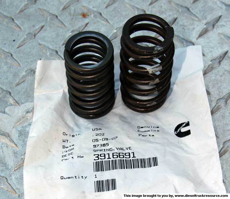
We're using the 60# springs, Cummins part number ~ 3916691. Only six (6) are required for the exhaust valves if you're installing an engine brake. Twelve for both the intake and exhaust if your goal is performance related.
As you can see, they're very different. (OEM/Stock on the left) ~
To remove the old and install the new, we're gonna need some means of compressing the springs for the purpose of removing/installing the Collets (those widgets that key into the valve stem and lock the assembly together).
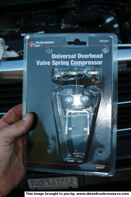
In this case, we're not removing the head, so what ever we do has to be done from above the engine. It's my understanding that the tool available comes in two different designs; Cam Style, and Screw Style. Some folks apparently don't care for the Cam Style and recommend using the Screw Style as it's easier to work with. Works for me! LOL!
KD Tools makes one, P/N 2078. I found the equivalent from Performance Tool for about $20. P/N W84001 ~
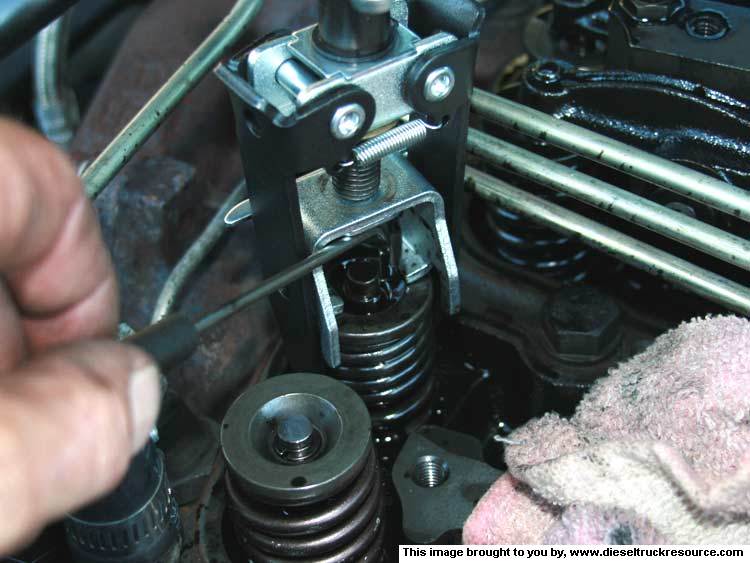
The tool rests on top of the valve and spring assembly and using hooks and tabs, grips the spring from both ends. One arm is longer than the other so things aren't crooked. ~
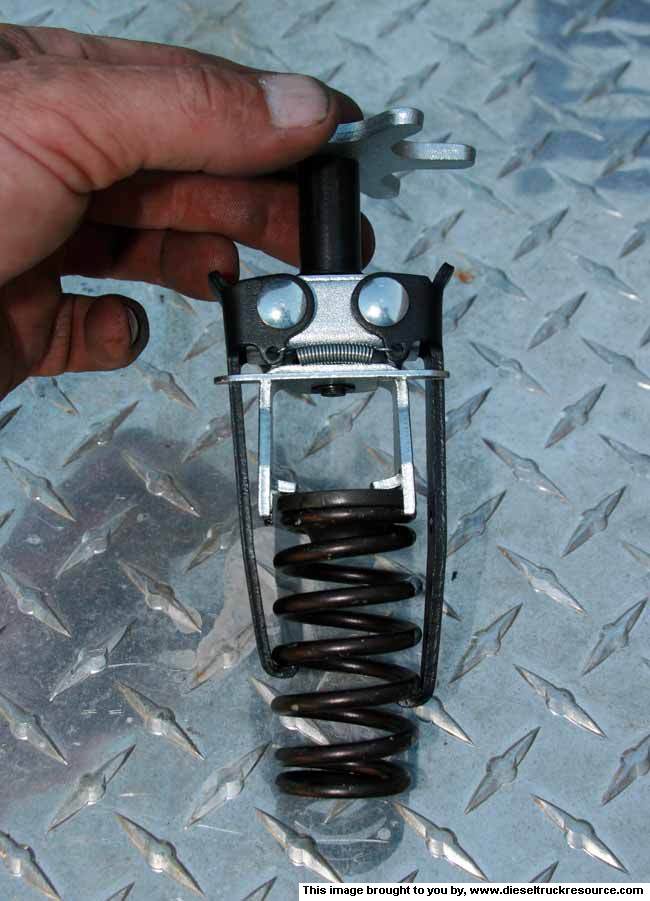
Tightening the big thumb-screw has the tabs up top push down compressing the spring there-by exposing the collets. ~
OK, fine.
- Start by removing your valve covers exposing the tops of the push-rods, the rocker arms, and the valve and spring assemblies. ~
- Loosen all the jam-nuts and the adjustment screws substantially. This is to help ensure we don't don't have any weird binding as we take things apart. ~

- Working with one cylinder at a time . . . .
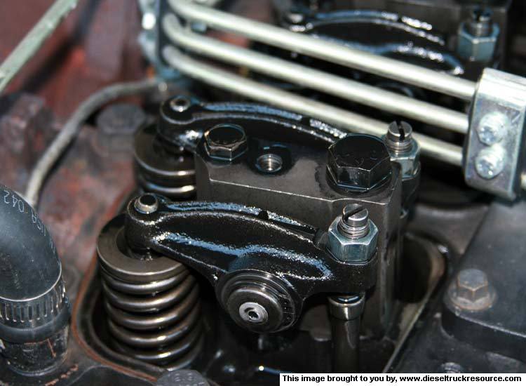
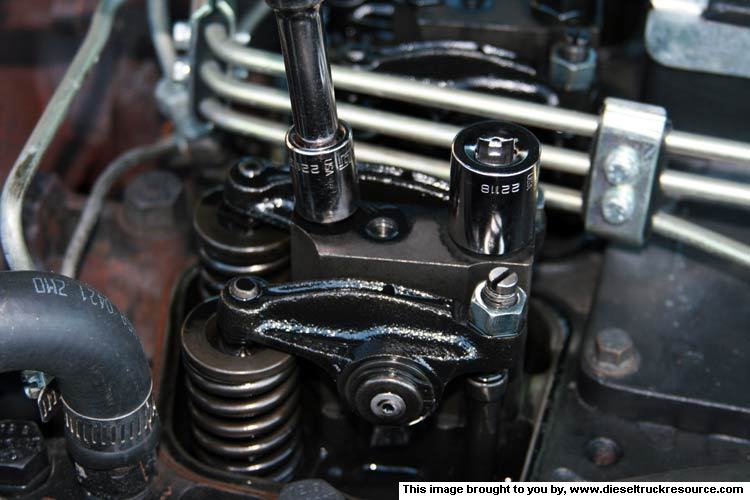
- Remove the rocker-arm/Pedestal assembly by first removing the smaller bolt. Then the remaining head bolt. You'll need a good sized wrench for the head bolts. ~
If you're planing on installing an engine exhaust brake or want to try your luck with a 4K governor spring, this upgrade is for you.
With recently completing the overhaul/upgrade of my heap's transmission, . . ... well, . . .. The wife wants her halve of the loot, so I'm broke. There, I said it.
I can't sit still though, so this is a good upgrade as it's inexpensive relatively speaking.
As part of my general plan of a good foundation, I'm replacing the OEM issue valve springs with the so called 60# version. While I don't know (at this point) that I'll be revving my mess to the point that I'm risking floating the valves, I've read things here, and there, that suggest there are occasions where the valves may be just kissing the pistons leaving prints in the carbon. How nice! I suspect I'm speaking WAY out of my league though.
Anyhoot, it's not a big deal and I'm bored stupid. Check it out . . . ...
This is by no means "The Authoritative How-To" regarding working with the CTD's valve springs. After searching these and other CTD related websites, this is what I came up with.
NOTE: I'm working on the typical 1993 W250 running OEM/Stock Cummins valve springs P/N 3900276.
As always ~ SAFETY FIRST!
- Chock the wheels as needed.
- Disconnect the Negative battery cable from the battery.
- Have a known good fire extinguisher within sight.
- Have a clean, uncluttered work area.
- Have good lighting.
- You'll need a means of leaning/laying over and into the engine bay so have the appropriate stool or such.
- WEAR SAFETY GLASSES for sure here folks.
Alright,
We're using the 60# springs, Cummins part number ~ 3916691. Only six (6) are required for the exhaust valves if you're installing an engine brake. Twelve for both the intake and exhaust if your goal is performance related.
As you can see, they're very different. (OEM/Stock on the left) ~
To remove the old and install the new, we're gonna need some means of compressing the springs for the purpose of removing/installing the Collets (those widgets that key into the valve stem and lock the assembly together).
In this case, we're not removing the head, so what ever we do has to be done from above the engine. It's my understanding that the tool available comes in two different designs; Cam Style, and Screw Style. Some folks apparently don't care for the Cam Style and recommend using the Screw Style as it's easier to work with. Works for me! LOL!
KD Tools makes one, P/N 2078. I found the equivalent from Performance Tool for about $20. P/N W84001 ~
The tool rests on top of the valve and spring assembly and using hooks and tabs, grips the spring from both ends. One arm is longer than the other so things aren't crooked. ~
Tightening the big thumb-screw has the tabs up top push down compressing the spring there-by exposing the collets. ~
OK, fine.
- Start by removing your valve covers exposing the tops of the push-rods, the rocker arms, and the valve and spring assemblies. ~
- Loosen all the jam-nuts and the adjustment screws substantially. This is to help ensure we don't don't have any weird binding as we take things apart. ~
- Working with one cylinder at a time . . . .
- Remove the rocker-arm/Pedestal assembly by first removing the smaller bolt. Then the remaining head bolt. You'll need a good sized wrench for the head bolts. ~
Thread Starter
1st Generation Admin
Joined: Jan 2005
Posts: 4,601
Likes: 118
From: Buies Creek, NC
With the rocker-arm assembly out of the way, you can see the individual intake and exhaust valves & springs as well as the associated push-rods.
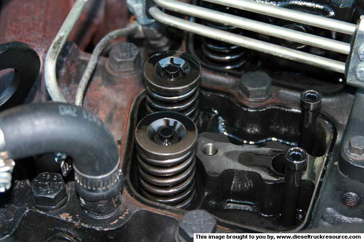
- At this point, it's a good time to wipe the surface that the valve cover gasket sits on. Then dab the oil that's puddled in the tops of the valves & springs. MAKE SURE YOU DO THIS!
- Finally, force the shop rag in and around the push-rods so that if you drop one of the collets, it won't fall into the engine. Cut a corner here, and you WILL be sorry.


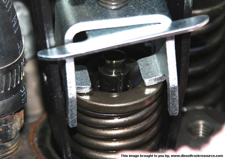
- Now place the compressor tool on the valve/spring you're working with and be sure the arms are well engaged with the valve spring. Tighten the tool, compressing the spring almost to the point that the spring coils are against one another.
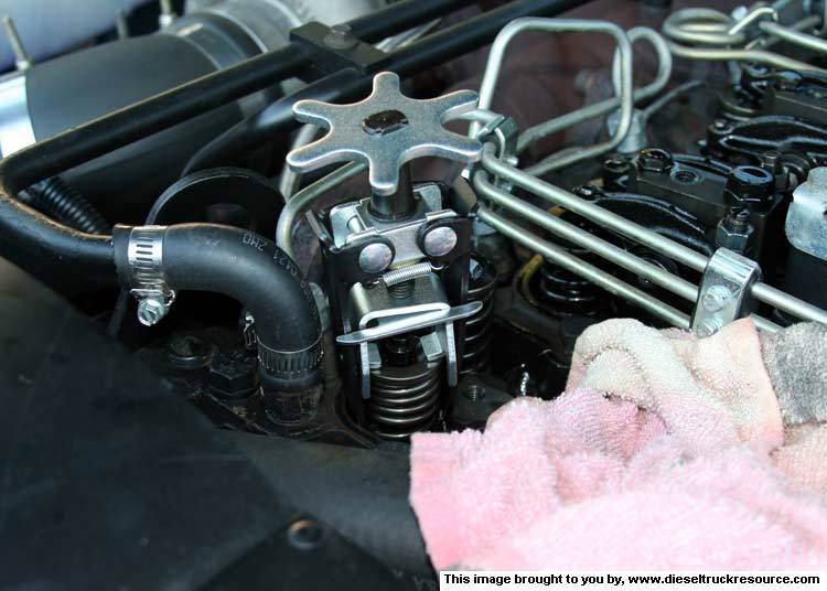
- Here, we need to bring the piston up so that the valve can't drop into the cylinder when we remove the spring. I simply gently pushed the tool, valve and all down so that the valve would just be open a little. Using the alternator pulley bolt, I barred the engine over slowly to the point where the piston just began to lift the valve. Stop there as again, we only want to keep the loose valve from falling into the cylinder where we can't get it back out.
- Having done so, I took a small brass headed hammer and gave the valve spring retainer a little love tap. After one or two, the retainer will pop off the collets. Had you not dabbed up the oil as I mentioned above, it would have Spritzed you in the face. Ask me how I know. DOH!!
- I used a small magnetic pick to remove the collets from the valve stem. BE CAREFUL NOT TO DROP THE COLLETS! Put them where you can't lose them.
- Now lift the tool and the captive spring from the engine. Unscrew the compressor to remove the old spring.
- Position the new spring with the retainer in the compressor and sorta screw the spring into the compressor so that it's trying to compress the spring without tightening the tool. I found it necessary to do this so that when you go to put the new spring back in, you'll have enough room to work with the collets. Don't forget the spring retainer!

- OK, if you're gonna replace your valve-stem oil seals, now's the time to do it.
- When you're ready, position the new compressed spring and retainer onto the valve-stem.
- CAREFULLY reinstall the collets onto the valve-stem making sure they go in the correct way (small end down). You'll see.
- With the collets in the correct position, unscrew the spring compressor and remove the tool.
- Cupping your hand over the newly installed spring, gently tap the retainer with your hammer so as to ensure the collets are fully seated into the valve-stem as well as the spring retainer.
- Repeat the above for the remaining spring of that individual cylinder.
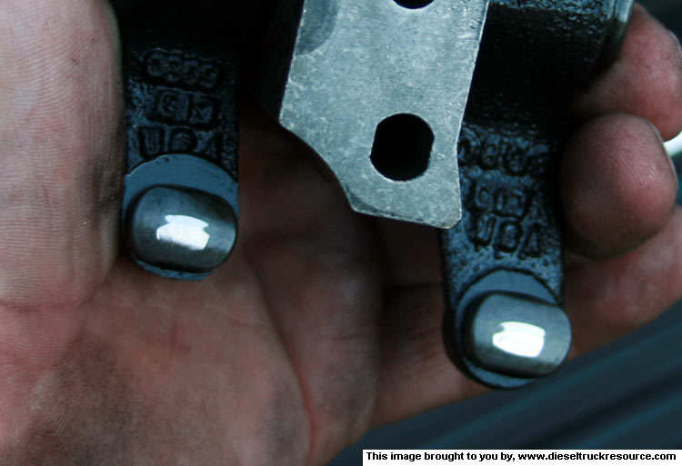
- Before you reinstall the rocker-arm assembly, look at where the individual rocker-arms contact the valve-stem. Check for any hints of unusual wear such as a slot worn into the rocker where it rides the valve-stem. After 224 thousand miles, mine were next to pristine. If you find evidence of a slot being worn into the rocker, you can machine it flat again provided you make sure it's exactly parallel to the stem when complete. Otherwise, remember that each time you adjust your valves, you'll need to use the narrow type feeler guage to fit into the slot. Don't, a wider guage may ride on the lip if you will, giving you false measurements.
- At this point, it's a good time to wipe the surface that the valve cover gasket sits on. Then dab the oil that's puddled in the tops of the valves & springs. MAKE SURE YOU DO THIS!
- Finally, force the shop rag in and around the push-rods so that if you drop one of the collets, it won't fall into the engine. Cut a corner here, and you WILL be sorry.
- Now place the compressor tool on the valve/spring you're working with and be sure the arms are well engaged with the valve spring. Tighten the tool, compressing the spring almost to the point that the spring coils are against one another.
- Here, we need to bring the piston up so that the valve can't drop into the cylinder when we remove the spring. I simply gently pushed the tool, valve and all down so that the valve would just be open a little. Using the alternator pulley bolt, I barred the engine over slowly to the point where the piston just began to lift the valve. Stop there as again, we only want to keep the loose valve from falling into the cylinder where we can't get it back out.
- Having done so, I took a small brass headed hammer and gave the valve spring retainer a little love tap. After one or two, the retainer will pop off the collets. Had you not dabbed up the oil as I mentioned above, it would have Spritzed you in the face. Ask me how I know. DOH!!
- I used a small magnetic pick to remove the collets from the valve stem. BE CAREFUL NOT TO DROP THE COLLETS! Put them where you can't lose them.
- Now lift the tool and the captive spring from the engine. Unscrew the compressor to remove the old spring.
- Position the new spring with the retainer in the compressor and sorta screw the spring into the compressor so that it's trying to compress the spring without tightening the tool. I found it necessary to do this so that when you go to put the new spring back in, you'll have enough room to work with the collets. Don't forget the spring retainer!
- OK, if you're gonna replace your valve-stem oil seals, now's the time to do it.
- When you're ready, position the new compressed spring and retainer onto the valve-stem.
- CAREFULLY reinstall the collets onto the valve-stem making sure they go in the correct way (small end down). You'll see.
- With the collets in the correct position, unscrew the spring compressor and remove the tool.
- Cupping your hand over the newly installed spring, gently tap the retainer with your hammer so as to ensure the collets are fully seated into the valve-stem as well as the spring retainer.
- Repeat the above for the remaining spring of that individual cylinder.
- Before you reinstall the rocker-arm assembly, look at where the individual rocker-arms contact the valve-stem. Check for any hints of unusual wear such as a slot worn into the rocker where it rides the valve-stem. After 224 thousand miles, mine were next to pristine. If you find evidence of a slot being worn into the rocker, you can machine it flat again provided you make sure it's exactly parallel to the stem when complete. Otherwise, remember that each time you adjust your valves, you'll need to use the narrow type feeler guage to fit into the slot. Don't, a wider guage may ride on the lip if you will, giving you false measurements.
Thread Starter
1st Generation Admin
Joined: Jan 2005
Posts: 4,601
Likes: 118
From: Buies Creek, NC
- Reposition the rocker-arm assembly onto the engine. Be sure the valve push-rod cups have the ball of the adjustment nuts resting in them. You'll see.
- Install the smaller bolt of the two followed by the head-bolt. Don't tighten them just yet, just snug them up ensuring the rocker-arm pedestal is correctly seated onto the head.
- Repeat the above for the remaining cylinder valve groups.
Having completed the replacement of the valve springs, we'll need to focus on re-torquing the head-bolts (THE BIG BOLTS on the right facing the front of the engine).
With the cylinder closest to the radiator being cylinder number one . . . .
- Tighten rocker-arm/head-bolt number four (4) to 66ft/lbs.
- Tighten rocker-arm/head-bolt number three (3) to 66ft/lbs.
- Tighten rocker-arm/head-bolt number five (5) to 66ft/lbs.
- Tighten rocker-arm/head-bolt number two (2) to 66ft/lbs.
- Tighten rocker-arm/head-bolt number six (6) to 66ft/lbs.
- Tighten rocker-arm/head-bolt number one (1) to 66ft/lbs.
- Using the same sequence, check each bolt to ensure it's at 66ft/lbs. If not, tighten it to 66ft/lbs.
Now, using the same tightening sequence,
- Tighten rocker-arm/head-bolt number four (4) to 89ft/lbs.
- Tighten rocker-arm/head-bolt number three (3) to 89ft/lbs.
- Tighten rocker-arm/head-bolt number five (5) to 89ft/lbs.
- Tighten rocker-arm/head-bolt number two (2) to 89ft/lbs.
- Tighten rocker-arm/head-bolt number six (6) to 89ft/lbs.
- Tighten rocker-arm/head-bolt number one (1) to 89ft/lbs.
- Using the same sequence, check each bolt to ensure it's at 89ft/lbs. If not, tighten it to 89ft/lbs.
- Finally, tighten the head-bolts, in sequence an additional 90 degrees.
- Now tighten the smaller bolts to 18ft/lbs.
- To complete this work, you'll now need to re-adjust your valve clearances as per standard procedure. .010" for the intake valves, and .020" for the exhaust valves (stock/OEM).
- Wipe clean the valve-cover gaskets as well as the covers mating surfaces.
- Reinstall the valve-covers with gaskets and tighten the bolts to 18ft/lbs.
There you go!
Y'all drive careful.
DTR's "Cooler than ice cubes 14 miles North of North Pole" member
Joined: Oct 2006
Posts: 1,797
Likes: 9
From: 14mi North of North Pole
Excellent once again! I really enjoy your write-ups and this one was no exception. Thanks for the future help this will be.
Now on to the Sticky I expect.
Now on to the Sticky I expect.

The 'Ford does not own Cummins' enforcer.
Joined: Sep 2007
Posts: 932
Likes: 0
From: Easton, pa
very nice lay out....now how much do u want to come work on my truck dtr style....tell me everything i need to buy i'll bring the beer you bring yourself and others and tools .......
Trending Topics

Registered User
Joined: Mar 2007
Posts: 113
Likes: 0
Very Nice work just like all the how to's i have seen that you wrote! 
1 question for you though. When we replace the valve springs on a import with the cylinder head on we do the same procedure except we torque down the cylinder one at a time before moving to the next cylinder.
Now do we not have to do this on the CTD because they don't use a aluminum head?
I always thought we did that to keep a seal on the head gasket at all times instead of breaking the seal completely but i could be wrong
Anyway great job!!!
Chris
Thread Starter
1st Generation Admin
Joined: Jan 2005
Posts: 4,601
Likes: 118
From: Buies Creek, NC
Thanks for the kind words folks.
On a truly stock engine, meaning nothing done with the injection pump (no additional fuel), etc, then I would think not. HOWEVER: If you're installing an engine exhaust brake, you'll need to install the 60# springs on the exhaust valves at a minimum. Check with your exhaust brake manufacturer.
I failed to mention that the jest of the procedure is by word of the FSM. They show the method specific to doing it without removing the head. The way I see it: you're pretty-much starting in the center of the head and pressing any wrinkles outward by moving from the center bolts outward . . . . sorta. 
I won't lie to you, that last quarter turn kinda skert me a little.
1 question for you though. When we replace the valve springs on a import with the cylinder head on we do the same procedure except we torque down the cylinder one at a time before moving to the next cylinder.
Now do we not have to do this on the CTD because they don't use a aluminum head?
I always thought we did that to keep a seal on the head gasket at all times instead of breaking the seal completely but i could be wrong
Now do we not have to do this on the CTD because they don't use a aluminum head?
I always thought we did that to keep a seal on the head gasket at all times instead of breaking the seal completely but i could be wrong
I won't lie to you, that last quarter turn kinda skert me a little.

Registered User
Joined: Mar 2006
Posts: 434
Likes: 0
From: North Idaho
:Raises hand:
Theres a problem with ur process.
I have the same set of springs for my head. Went to put them on the other day and came up with too much seat pressure. 160lbs to be exact. Flat tappet cams like 80- 140ish pounds of seat pressure to live or they will go flat.
Might check your seat pressure to verify it. Camshaft might live too. Last one I seen with heavy springs Had all kinda pits in it and the one exhaust lobe wasnt the greatest.
Im gonna see if I can get some plus .050 locks and change the install height or end up cutting the seat pockets to get my seat pressure down.
It never ends on hassles to built something.
 The last time I did springs on an installed head it was on a gasser and I need air to hold the valves up.
Thread Starter
1st Generation Admin
Joined: Jan 2005
Posts: 4,601
Likes: 118
From: Buies Creek, NC
:Raises hand:
Theres a problem with ur process.
I have the same set of springs for my head. Went to put them on the other day and came up with too much seat pressure. 160lbs to be exact. Flat tappet cams like 80- 140ish pounds of seat pressure to live or they will go flat.
Might check your seat pressure to verify it. Camshaft might live too. Last one I seen with heavy springs Had all kinda pits in it and the one exhaust lobe wasnt the greatest.
Im gonna see if I can get some plus .050 locks and change the install height or end up cutting the seat pockets to get my seat pressure down.
It never ends on hassles to built something.
Theres a problem with ur process.
I have the same set of springs for my head. Went to put them on the other day and came up with too much seat pressure. 160lbs to be exact. Flat tappet cams like 80- 140ish pounds of seat pressure to live or they will go flat.
Might check your seat pressure to verify it. Camshaft might live too. Last one I seen with heavy springs Had all kinda pits in it and the one exhaust lobe wasnt the greatest.
Im gonna see if I can get some plus .050 locks and change the install height or end up cutting the seat pockets to get my seat pressure down.
It never ends on hassles to built something.
I dunno friend. I did this swap as per instruction of the factory service manual (FSM) going on two years ago (about 6000 miles now) and am unaware of any problems. Ran the eighth mile in 8.44 @ 79.xx again the other night with this 6400lb heap.
I am curious if you might know the installed hight of the Cummins springs so as to arrive at the expected valve seat pressure. I've dug around and haven't been able to find any thing definitive.
"end up cutting the seat pockets to get my seat pressure down"
A word of caution on that. The Cummins head uses integral induction hardened valve seats that can typically only be cut once, and a little at that. Any more required service/replacement seats to be installed in the head.
To help confirm your concerns though, I expect to pull my factory stock/OEM cam out this coming week and replace it with a Hamilton 181/220. I'll also be replacing the stock/OEM ('93 vintage) lifters and replace them with some 24v lifters. I'll be swapping in some chromaloy rush-rods to help better control any flexing there.
I figure you're aware of the evolving engine lube oil's ever changing chemical compositions that have pretty-much mandated Cummins to widen the cam lobes and lifter faces to better accommodate the pressure(s) at the lobe/lifter interface. It's my understanding that a zinc compound/element is no longer a standard component of today's engine oils and is the main culprit in the hardware changes. There are zinc additives available to us to help better address such concerns in a more demanding application.
With over 230,000 miles over the last 16 years or so, combined with my hot-rodding the mess over the last four or so years, and finally the fact I've been beating the snot out of it (FWIW) over the last three years an eighth and quarter mile at a time. . . . any wear should be clear with the stock/OEM cam's removal. There will be a cam related how-to in the very near future.
I am very interested in any information you may have regarding the Cummins 60lb spring install height.

Banned
Joined: Oct 2003
Posts: 885
Likes: 3
From: Western PA
BC847. I was wondering if you found any evidence or problems when you did remove the cam ? I know this thread is kinda old, but just picking your brain.
I am in the middle of rebuilding/maintaining a spare motor. I was wondering if the 60 lb springs is considered a good upgrade or not for a basically stock set-up, or a mildly (injectors/ fuel pin) set-up.
I am in the middle of rebuilding/maintaining a spare motor. I was wondering if the 60 lb springs is considered a good upgrade or not for a basically stock set-up, or a mildly (injectors/ fuel pin) set-up.