Resealing 93 VE Injection Pump
 10-06-2011, 11:32 AM
#16
Registered User
Thread Starter

I removed one front seal from the front, with the shaft still in place...it sucked big time!! Easier to just pull the internals out of the pump and pop it out from the inside...makes re-installing it much easier as well.
You already have the head off...the rest comes out easily. Just take lots of pics as you take it apart, and lay everything out in a clean, organised maner.
You already have the head off...the rest comes out easily. Just take lots of pics as you take it apart, and lay everything out in a clean, organised maner.
 10-06-2011, 02:09 PM
#17
Registered User
I was intimidated the first time I did an IP...and this was when I did the front seal with the internals still in place. I ended up screwing up that pump...with not securing that little thrust washer that goes between teh piston head and cam plate, with a dab of grease....
Anyway the next pump I did I pulled it completely apart...they are a very simple design, and don't be afraid to tear it down the rest of the way. Made life so much simpler, and I learned a ton as well.
Anyway the next pump I did I pulled it completely apart...they are a very simple design, and don't be afraid to tear it down the rest of the way. Made life so much simpler, and I learned a ton as well.
10-06-2011, 07:13 PM
#18
I was intimidated the first time I did an IP...and this was when I did the front seal with the internals still in place. I ended up screwing up that pump...with not securing that little thrust washer that goes between teh piston head and cam plate, with a dab of grease....
Anyway the next pump I did I pulled it completely apart...they are a very simple design, and don't be afraid to tear it down the rest of the way. Made life so much simpler, and I learned a ton as well.
Anyway the next pump I did I pulled it completely apart...they are a very simple design, and don't be afraid to tear it down the rest of the way. Made life so much simpler, and I learned a ton as well.
10-06-2011, 09:05 PM
#19
Registered User
Thread Starter
I noticed that the drive nub/pin, just off of center, on this cam can be lined up with the key on the front of the shaft, or 180 degrees out from it. I forgot to check as I took it apart. Which way does it go back in?
By the way, there is, so far, no sign of a shim that goes into the head. I never saw it when I took it apart. It hasn't shown up as I continue on either. Maybe it didn't have one? This is a rebuilt pump from Chrysler.
By the way, there is, so far, no sign of a shim that goes into the head. I never saw it when I took it apart. It hasn't shown up as I continue on either. Maybe it didn't have one? This is a rebuilt pump from Chrysler.
10-07-2011, 03:24 AM
#20
Registered User
Thread Starter
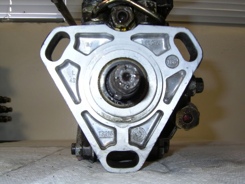
There seems to be a way that the fuel system is keyed to the key way on the tapered shaft of the pump.
The blue arrow in this image is the output of the fuel to the 6 outlet ports on the head, which is not installed in this pic. It resembles a key way slot. But it's not. There is one on the other side of the shaft too, but it has no hole for fuel to pass through. So it seems to me that the fuel hole should be aligned to the key on the tapered end of the pump shaft. That's how I found it originally. So that's how it's going back.
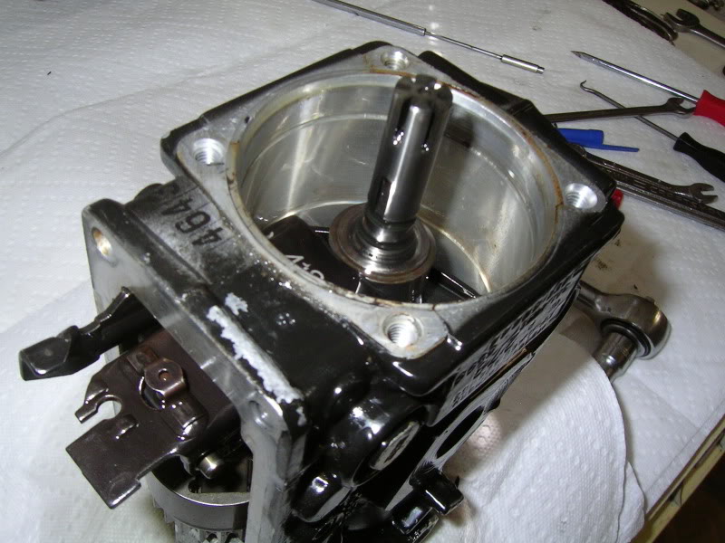
As for my previous post, the drive pin of this cam plate should also be pointed to the key of the tapered end of the pump shaft during reassembly.
I have not found reference to this before. Let me know if I'm off base.
Edit: Here is a build article of a smaller VE pump. The guys states that alignment of the drive pin should be to the key on the end of the pump shaft. http://gnarlodious.com/Vanagon/Bosch_Pump/-Rebuild#53
The blue arrow in this image is the output of the fuel to the 6 outlet ports on the head, which is not installed in this pic. It resembles a key way slot. But it's not. There is one on the other side of the shaft too, but it has no hole for fuel to pass through. So it seems to me that the fuel hole should be aligned to the key on the tapered end of the pump shaft. That's how I found it originally. So that's how it's going back.
As for my previous post, the drive pin of this cam plate should also be pointed to the key of the tapered end of the pump shaft during reassembly.
I have not found reference to this before. Let me know if I'm off base.
Edit: Here is a build article of a smaller VE pump. The guys states that alignment of the drive pin should be to the key on the end of the pump shaft. http://gnarlodious.com/Vanagon/Bosch_Pump/-Rebuild#53
10-07-2011, 03:37 AM
#21
Registered User
Thread Starter
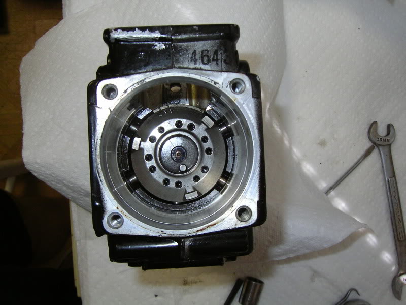
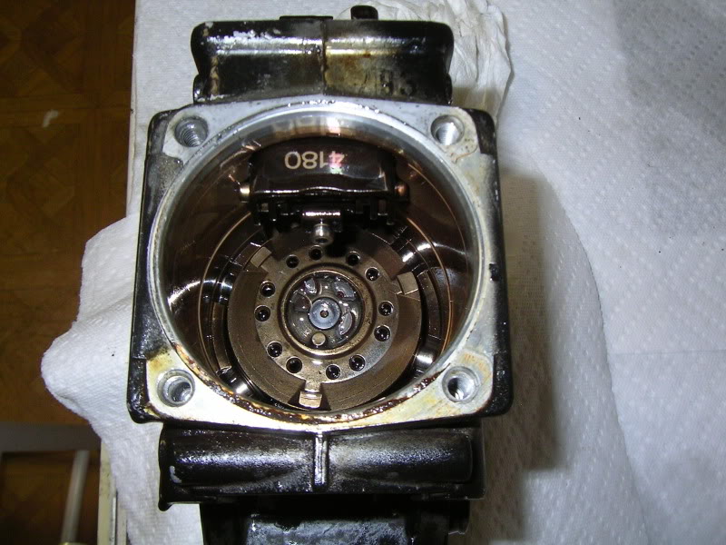
Does the thrust washer go under the governor weights feet or above the feet?
This pic shows the thrust washer under the weights feet. Is this correct?
I missed getting the pic as the governor fell apart on me suddenly as I disassembled it.
EDIT: Alo I'm wondering if the small circle at about the 5 oclock position is a timing mark? There is another one 180 degrees across the gear, but it it's hidden behind the shaft in this pic. I could not find a matching one on the mating gear. But the mating gear is installed, so a timing mark may be obstructed?
10-07-2011, 05:33 PM
#22
Registered User
Here are some pics of when I re-did my second IP.
Hope this helps with your alignement and re-assembly.
As for the thrust washer on the govenor...no idea...I kept mine all in one piece.
Oh and here's the little thrust washer you seem to be missing...
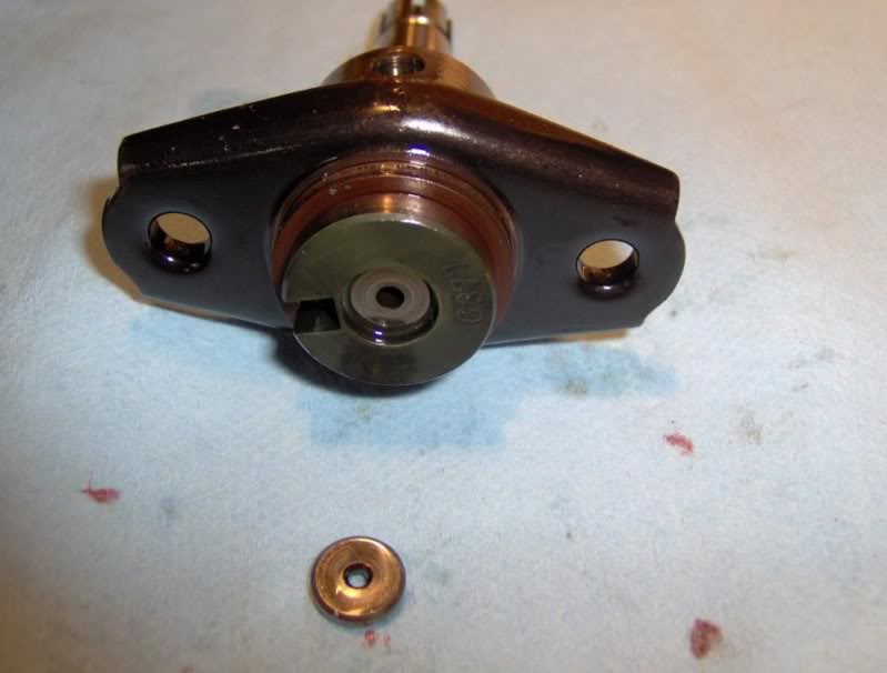
And this is what will happen if you don't hold it in place with a dab of grease....
Hope this helps with your alignement and re-assembly.
As for the thrust washer on the govenor...no idea...I kept mine all in one piece.
Oh and here's the little thrust washer you seem to be missing...
And this is what will happen if you don't hold it in place with a dab of grease....
10-07-2011, 07:54 PM
#24
Registered User
Thread Starter
Thanks Thrashingcow, I did use vaseline on that thrust washer to hold it in place thanks to your previous advice. I was missing a thrust shim that goes into the center bore of the head. Mind just didn't have one.
Your pin alignment on the cam is facing toward the key way of the pump shaft. That's how it's is suppose to be as I found out comparing my pics under magnification. Thanks for your pics!
I did find that I may have put the washer into the governor incorrectly. Here is a guy doing his pump. He added the washer above the feet of the weights. I put it below the feet.
http://gnarlodious.com/Vanagon/Bosch_Pump/-Rebuild#75
Anyone else have a pic of the governor weights of their VE pump tear down??
10-07-2011, 11:55 PM
#25
Registered User
Thread Starter
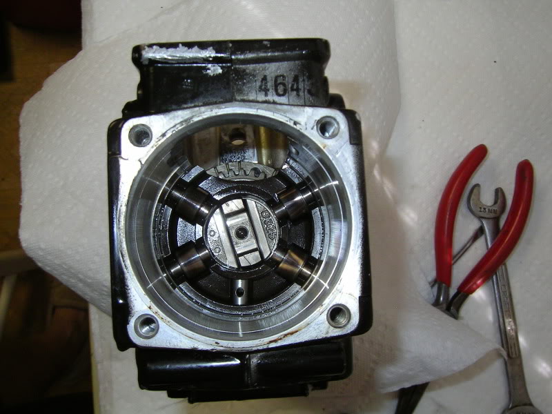
I tore the top of the pump off again and put the thrust washer on top of the feet of the governor weights. The blow up diagram shows the washer this way as well.
This pic shows that the thrust washer is just behind the black governor sleeve. The thrust washer almost looks a little blue in the pic. But it's on top of the feet.
Just need to pull the back 25mm 3 point plug out of the head and replace that oring. Then the pump goes back in the truck!
This pic shows that the thrust washer is just behind the black governor sleeve. The thrust washer almost looks a little blue in the pic. But it's on top of the feet.
Just need to pull the back 25mm 3 point plug out of the head and replace that oring. Then the pump goes back in the truck!
10-08-2011, 10:08 AM
#26
Registered User
Thread Starter
I was intimidated the first time I did an IP...and this was when I did the front seal with the internals still in place. I ended up screwing up that pump...with not securing that little thrust washer that goes between teh piston head and cam plate, with a dab of grease....
Anyway the next pump I did I pulled it completely apart...they are a very simple design, and don't be afraid to tear it down the rest of the way. Made life so much simpler, and I learned a ton as well.
Anyway the next pump I did I pulled it completely apart...they are a very simple design, and don't be afraid to tear it down the rest of the way. Made life so much simpler, and I learned a ton as well.
I did leave in the pump vanes and use a screw driver to pull the front seal out. Having the pump shaft out of the way made it easier. Since there was nothing to replace around the pump vanes, and the internals were sterile, I thought I would save myself the work.
 10-09-2011, 01:39 AM
#28
Registered User
Thread Starter
The first socket was one I modified for removing injection lines from the rear of the pump. It wasn't stiff enough. It would just turn around the hexes. I could have tried using an impact socket, but I didn't want to spend the time. So I went and bought a set of crow foot flare wrenches instead.
Here are the last pics from the final operation. The large 3 pt plug in the rear of the pump finally got removed with a 1 inch socket that I cnc'd. The socket was a bit sloppier than I wanted. I suspect a 24 or 25 mm socket would have fit better as they are a bit smaller. But this baby worked just fine. I used a 1/2" socket for the 3 point bolts on each side of the pump. Again, not perfect but worked great anyway.
10-09-2011, 07:44 PM
#29
Registered User
Thread Starter
I got the old girl back together today. Manually pumped the lift pump and then cranked the engine, repeat. Only took maybe 5 cycles to get it to start. Bled the injectors 3 times too.
Before I 'rebuilt' this pump, the engine never smoked. Now it smokes a light gray at idle and volumes on acceleration. But the power is down to only 30% of what it use to have.
The only clue I can think of is that this pump didn't have a mark on it to match to the block on the mounting ear. So this time I eyeballed it for center. Looks fine. The micro switch that was added for the exhaust brake by a previous owner, is no longer aligned with the throttle ball link on the throttle arm. The pump is now rotated towards the engine a little more. I think this is more advanced from what I've read. Is this difference significant enough to cause this huge lack of power?
The engine sounds funny too. To my ears it sounds like it's pinging if you can believe that. There is an additional high frequency sound to each cylinder on top of the normal diesel noise, when I push the throttle to 1/4-1/2.
I have been frantically searching for the answer and need your help.
PS The pic of my timing mark is before I removed the pump.
PSS The stop lever on the drivers side of the pump toward the bottom, is not connected to anything. I didn't get a pic of it before removal. Is it suppose to be connected to something? It has a hole in the arm.
10-09-2011, 11:15 PM
#30
Registered User
Well glad to hear that it's up and running...sucks that it has new issues now. Kind of sounds a bit like my motor though. I have hazing at idle, not too bad, and it does load up and smoke in the lower rpm range while driving adn shifting. I personally think it's a bad injector...or two. I too have a tinny/rattle noise...and I've adjusted my valves 6 times in the last year because it sure sounds like a valve train noise.
I have no other 1st gen to compare my motor noises to, so I'm just guessing, and hoping that they are "normal". I've spent considerable time watching...and listening to Youtube videos of 1st gen's, trying to "hear" the noises.
The manual shut down lever is not attatched to anything from the factory. Now if you wanted to install your own manual shut down system you know where to hook the cable to....