
Oooops I goofed


Thread Starter
Registered User
Joined: Apr 2003
Posts: 295
Likes: 0
From: Gentryville, IN.
Oooops I goofed
While removing my dash bezel yesterday I broke a piece of the printed circut board off the message center.  While it doesn't seem to change the way anything works I like the idea of the WTS, WIF and brake warning light. I remember someone making a custom dash and using smaller lights for these. I've searched and can't find anything.
Does anyone know what the purpose of all the circuts with the resistors and such on the back of this board? Will I loose anything or cause problems by removing this? Does anyone have a spare laying around?
While it doesn't seem to change the way anything works I like the idea of the WTS, WIF and brake warning light. I remember someone making a custom dash and using smaller lights for these. I've searched and can't find anything.Does anyone know what the purpose of all the circuts with the resistors and such on the back of this board? Will I loose anything or cause problems by removing this? Does anyone have a spare laying around?
Adminstrator-ess

Joined: Mar 2003
Posts: 22,594
Likes: 19
From: New Holland, PA
If you still have both pieces you can glue them back together (think epoxy and a couple popsicle stick braces). Then scrape off the green enamel and solder jumper wires across the broken traces. It'll work like new - and nobody will see the ugliness behind the dash.
edit: They are just indicator lights. If they are missing everything will still work. There is a diagram in my FSM, it's probably the same as a '92.
edit: They are just indicator lights. If they are missing everything will still work. There is a diagram in my FSM, it's probably the same as a '92.
Thread Starter
Registered User
Joined: Apr 2003
Posts: 295
Likes: 0
From: Gentryville, IN.
I don't have the other pieces already hit the stove with them. Seems to be more than indicator lights back there. Is that something to do with the WTS timer, brake antilock or just more useless crap? Everything is working but the lights it seems so I guess I will keep my eyes open for a replacement.
1st Generation Admin
Joined: Jan 2005
Posts: 4,601
Likes: 118
From: Buies Creek, NC
For what it's worth . . . . .
There's some weird math going on with the circuit board.
By that I mean there are four diodes (a one-way checkvalve of sorts for electricity) that steer the direct current around pending which alarm circuit is tripped.
How does it work? Danged if I know! Those blue conductors may feed another circuit should one of those on the panel are activated.
I've made a little custom affair so I could shoe-horn in some gages. All I did was relocate the indicators, and convert them to LED's.
My point is those diodes are there. In the image below, you can see how they (shown in Black) are installed in the circuits of the board. (In the stock setting, one would see the LED's symbol as incandescent bulb symbols).

Click here for larger image
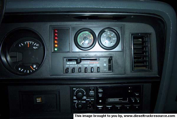
NOTE: That schematic for the LED's, the LED polarity may not be depicted accurately. I can't remember if I had to reverse them with the actual install.
There's some weird math going on with the circuit board.
By that I mean there are four diodes (a one-way checkvalve of sorts for electricity) that steer the direct current around pending which alarm circuit is tripped.
How does it work? Danged if I know!
Those blue conductors may feed another circuit should one of those on the panel are activated.I've made a little custom affair so I could shoe-horn in some gages. All I did was relocate the indicators, and convert them to LED's.
My point is those diodes are there. In the image below, you can see how they (shown in Black) are installed in the circuits of the board. (In the stock setting, one would see the LED's symbol as incandescent bulb symbols).
Click here for larger image
NOTE: That schematic for the LED's, the LED polarity may not be depicted accurately. I can't remember if I had to reverse them with the actual install.
1st Generation Admin
Joined: Jan 2005
Posts: 4,601
Likes: 118
From: Buies Creek, NC
Originally Posted by Underpsi
that is seriously sweet, id love to do that with my truck!! do you have a detailed write up on it with more pics?
") Stupid brake and ABS indicator's staying on crap has got me.
Stupid brake and ABS indicator's staying on crap has got me. 
As soon as it's all complete, I'm planning on sharing to all with some detail. You can check my gallery for additional pics of the gage panel. Once I get time to sort out any bugs, I'm gonna measure it all and post a thread.

Thread Starter
Registered User
Joined: Apr 2003
Posts: 295
Likes: 0
From: Gentryville, IN.
uhhhhh I uhhh believe that may be above my pay grade. But that is the pic I was thinking of. Sure does look nice.
I may have found one I will have to go check this week. Man I thought moving the OD switch to the shifter and putting the tranny temp guage in it's place was a tough one. Leave it to the first gen guys to come up with a great idea when they are up against a wall or a expensive dealer item. You guys never cease to amaze me with your ingenuity.
I may have found one I will have to go check this week. Man I thought moving the OD switch to the shifter and putting the tranny temp guage in it's place was a tough one. Leave it to the first gen guys to come up with a great idea when they are up against a wall or a expensive dealer item.
You guys never cease to amaze me with your ingenuity.
Trending Topics


Registered User

Joined: Apr 2002
Posts: 1,602
Likes: 93
From: Richmond, VA
Very good job!
That is exactly where those guages should be. It would be nice to be able to claim all that wasted space in the dash, so I look forward to your finished schematics.
Thanks!
That is exactly where those guages should be. It would be nice to be able to claim all that wasted space in the dash, so I look forward to your finished schematics.
Thanks!

Thread
Thread Starter
Forum
Replies
Last Post
Bill001
3rd Gen Engine and Drivetrain -> 2007 and up
12
Oct 26, 2007 06:30 AM
xtoyz17
12 Valve Engine and Drivetrain
6
Dec 31, 2006 03:18 PM