
Installing Headlamp Relays


Thread Starter
Administrator


Joined: Nov 2004
Posts: 4,084
Likes: 235
From: Southern California
Installing Headlamp Relays Part-1
Includes updated instructions for High Beam control using a DIODE instead of 3rd relay.
Instructions for optional 3rd. relay are included. (Now replaced using Diode)
Now that winter is upon us and it is going to be getting dark earlier now is a good time to upgrade your electrical system by installing relays to control your headlamps to provide them with the full output of your charging system and in return they will provide you with more usable light output and reduce the chances of burning up the light switch or worse your wiring harness.
I realize some of you do not know too much about electrical so I will make this modification easy to perform.
I made this Plug and Play so you can assemble this on your kitchen table and then take it out to your truck and simply plug it into your headlamp system.
Minimal tools will be required.
Although this is for out 1st. Gen. Trucks it is generic and will work on almost any single headlamp system excluding ones with Daytime Running Lamps.
I promise I will have something for you soon.
I have done the research and know what will work so all you have to do is follow along.
First all headlamp sockets are not created alike, The one in the foreground I bought from Pep Boys and is sold under the Motor-Mite name, it cost around $2.99.
Do not get these, they are junk, but they do have some that are suitable in the section where they have the aftermarket lights and dress up parts for the ricers and wanna-bees.
They are sold under the 3A Racing brand and the part number #469993 @ $8.99 each
They are for the high wattage H-4 lamps and looked to be well constructed and have 14-gauge pigtails, although a bit pricey.
I bought mine at my local truck parts as seen to the right of the cheap one; they are made by Cole Hersee
http://www.colehersee.com/catalog_top/index.htm
And are used on OTR tractors and other heavy equipment.
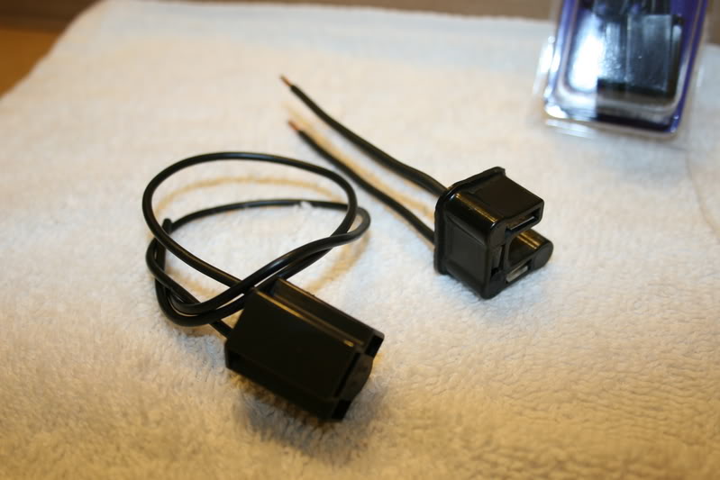
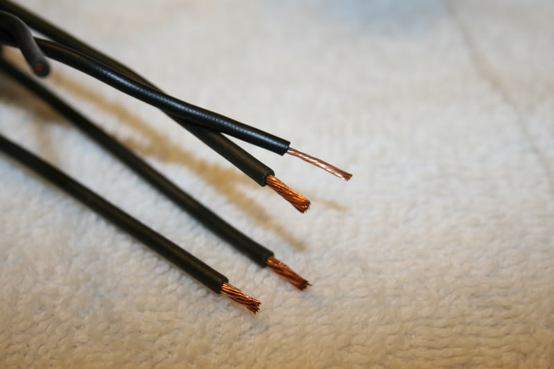
Here you can see the difference in the size of the wire. They look to be 18-gauge wire but since they are from China they would be a metric equivalent.
The ones on my socket are 14-gauge and as you can see quite a bit heavier.
On our trucks the entire Low Beam circuit is 16-gauge while the High Beam is 14-gauge wire.
The real weak link in the wiring are the grounds, they are only 20 gauge from the sockets to the first ground connection.
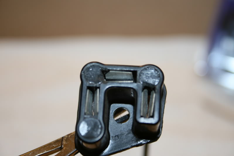
Here you can see the size of the connections to the headlamp.
Here is your parts list.
2) Premium grade headlight sockets.
2) 30-amp BOSCH ISO relays. Get the genuine thing, more on this.
8) 12-10 gauge uninsulated Butt Splice connectors. (I bought High Temperature connectors from a HVAC supply)
1) 30 amp self-resetting circuit breaker. (Truck Parts of RV supply)
4) 14-12-gauge insulated ring terminals.
2) 14 gauge insulated .250 male spade terminals.
8) 12 gauge insulated .250 female spade connectors. (Home Depot electrical department.)
3) Small rolls of 12 gauge automotive wire; you will need Red, Blue and Black
Miscellaneous items you will need,
Shrink tubing
Ty-Wraps (zip ties)
Convoluted tubing (Split Loom)
Tools:
Wire cutters.
Good terminal crimpers.
Sharpie marking Pen.
Now we get started, from your rolls of wire you will need to cut.
8 feet each of Red, Blue and Black wire.
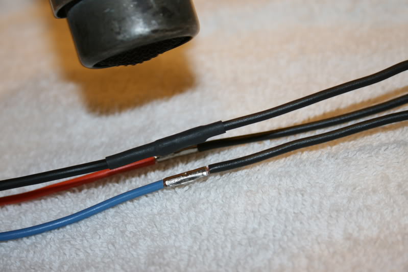
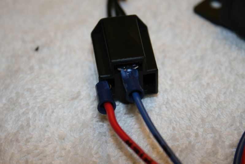
Looking at the socket with the wires FACING you, hold it like a �U� or a horseshoe.
The left wire is the High Beam, the bottom wire is the Low Beam and the right wire is the Ground.
It might also be marked on the socket.
Now,
Strip �� to 3/16� off the insulation and connect them together to the 3 lengths of cut wire.
Red = High Beam
Blue = Low Beam
Black = Ground
These high temperature connectors require a lot of muscle to crimp but they make an excellent connection.
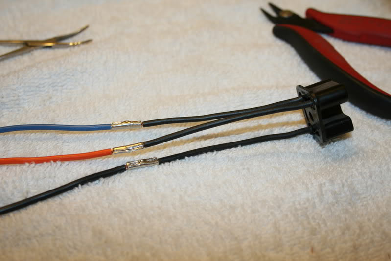
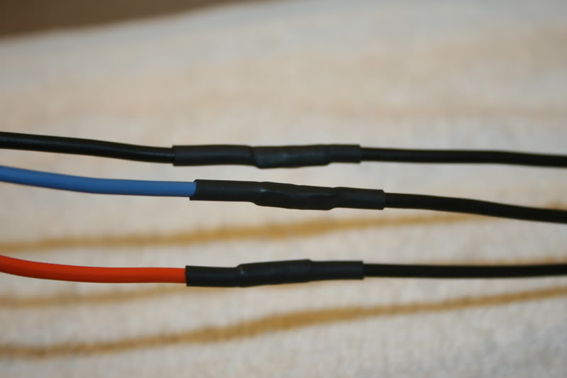
Now that you have made sure they are in the right position and the connection is tight, slide some ��shrink tubing over the center of the splice and heat it with a heat gun or carefully use a cigarette lighter to shrink the tubing to the wire and seal it tight.
You should have 3 nice looking connections when you are finished and hopefully no burned wires from the lighter that got too close.
Of course if you used regular insulated Butt Splice connectors you will have a lump on each wire, but that is OK.
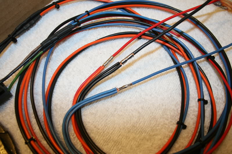
Straighten out the 3 wires and secure them with ty-wraps or even electrical tape to make a nice straight set of wires. When you get them all even, cut all of them at the opposite end of the socket so they are the same length.
This will be for the passenger side connection.
If you noticed I did use 2 different styles of sockets for demonstration purposes.
Now cut yourself 2 feet of the 3 colors of wire and repeat yourself with the other socket making another harness that will be used for the driver�s side connection.
Now take the opposite ends of both harnesses and make sure all of the ends are cut straight and then strip them back �� to 3/16� and holding the wires in pairs inset both wires into the same side of the Butt Spice connector and then crimp them securely.
Do this for all 6 wires; there should be 3 pairs of 2 when you are done.
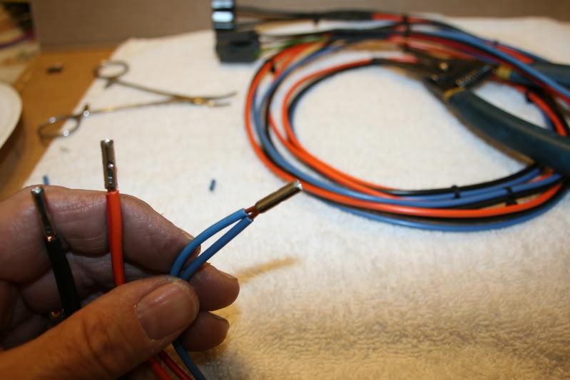
To the other side of the Butt Splice connector crimp a 6� length of wire the same corresponding color.
Check your connection and then again slip a piece of �� heat shrink tubing over the connection and shrink it into place.
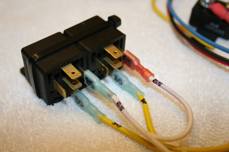
Next take your 2) 30-amp BOSCH relays and secure them together using a Ty-Wrap or electrical tape.
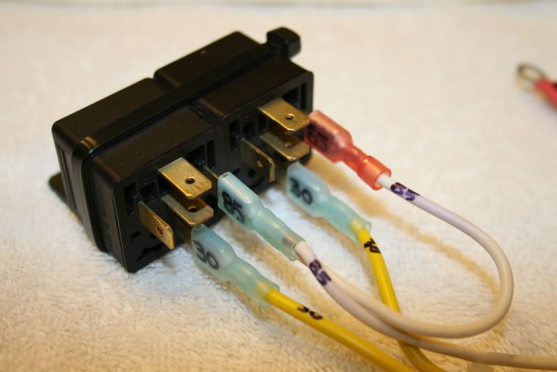
With a length of wire fashion a jumper and provide a pigtail, this will connect to terminal #85 on both relays using a Female Spade connector. On the end of the pigtail provide a ring terminal, this will be a Ground connection.
This is the WHITE wire in the picture, you should use a different color, you could use Black wire but it should not be Red or Blue for ease of identifying the circuit after it is installed. It is just easier to diagnose later on. If there is ever a problem.
Also cut 2 lengths of 12-gauge wire 24 inches long and secure an insulated Female Spade connector to the end of each one, pair them up and on the other end secure them together into the same Ring Terminal.
This will go to terminal #30 on both relays and will supply the power. This the yellow wires in the picture.
Continued.
Includes updated instructions for High Beam control using a DIODE instead of 3rd relay.
Instructions for optional 3rd. relay are included. (Now replaced using Diode)
Now that winter is upon us and it is going to be getting dark earlier now is a good time to upgrade your electrical system by installing relays to control your headlamps to provide them with the full output of your charging system and in return they will provide you with more usable light output and reduce the chances of burning up the light switch or worse your wiring harness.
I realize some of you do not know too much about electrical so I will make this modification easy to perform.
I made this Plug and Play so you can assemble this on your kitchen table and then take it out to your truck and simply plug it into your headlamp system.
Minimal tools will be required.
Although this is for out 1st. Gen. Trucks it is generic and will work on almost any single headlamp system excluding ones with Daytime Running Lamps.
I promise I will have something for you soon.
I have done the research and know what will work so all you have to do is follow along.
First all headlamp sockets are not created alike, The one in the foreground I bought from Pep Boys and is sold under the Motor-Mite name, it cost around $2.99.
Do not get these, they are junk, but they do have some that are suitable in the section where they have the aftermarket lights and dress up parts for the ricers and wanna-bees.
They are sold under the 3A Racing brand and the part number #469993 @ $8.99 each
They are for the high wattage H-4 lamps and looked to be well constructed and have 14-gauge pigtails, although a bit pricey.
I bought mine at my local truck parts as seen to the right of the cheap one; they are made by Cole Hersee
http://www.colehersee.com/catalog_top/index.htm
And are used on OTR tractors and other heavy equipment.
Here you can see the difference in the size of the wire. They look to be 18-gauge wire but since they are from China they would be a metric equivalent.
The ones on my socket are 14-gauge and as you can see quite a bit heavier.
On our trucks the entire Low Beam circuit is 16-gauge while the High Beam is 14-gauge wire.
The real weak link in the wiring are the grounds, they are only 20 gauge from the sockets to the first ground connection.
Here you can see the size of the connections to the headlamp.
Here is your parts list.
2) Premium grade headlight sockets.
2) 30-amp BOSCH ISO relays. Get the genuine thing, more on this.
8) 12-10 gauge uninsulated Butt Splice connectors. (I bought High Temperature connectors from a HVAC supply)
1) 30 amp self-resetting circuit breaker. (Truck Parts of RV supply)
4) 14-12-gauge insulated ring terminals.
2) 14 gauge insulated .250 male spade terminals.
8) 12 gauge insulated .250 female spade connectors. (Home Depot electrical department.)
3) Small rolls of 12 gauge automotive wire; you will need Red, Blue and Black
Miscellaneous items you will need,
Shrink tubing
Ty-Wraps (zip ties)
Convoluted tubing (Split Loom)
Tools:
Wire cutters.
Good terminal crimpers.
Sharpie marking Pen.
Now we get started, from your rolls of wire you will need to cut.
8 feet each of Red, Blue and Black wire.
Looking at the socket with the wires FACING you, hold it like a �U� or a horseshoe.
The left wire is the High Beam, the bottom wire is the Low Beam and the right wire is the Ground.
It might also be marked on the socket.
Now,
Strip �� to 3/16� off the insulation and connect them together to the 3 lengths of cut wire.
Red = High Beam
Blue = Low Beam
Black = Ground
These high temperature connectors require a lot of muscle to crimp but they make an excellent connection.
Now that you have made sure they are in the right position and the connection is tight, slide some ��shrink tubing over the center of the splice and heat it with a heat gun or carefully use a cigarette lighter to shrink the tubing to the wire and seal it tight.
You should have 3 nice looking connections when you are finished and hopefully no burned wires from the lighter that got too close.
Of course if you used regular insulated Butt Splice connectors you will have a lump on each wire, but that is OK.
Straighten out the 3 wires and secure them with ty-wraps or even electrical tape to make a nice straight set of wires. When you get them all even, cut all of them at the opposite end of the socket so they are the same length.
This will be for the passenger side connection.
If you noticed I did use 2 different styles of sockets for demonstration purposes.
Now cut yourself 2 feet of the 3 colors of wire and repeat yourself with the other socket making another harness that will be used for the driver�s side connection.
Now take the opposite ends of both harnesses and make sure all of the ends are cut straight and then strip them back �� to 3/16� and holding the wires in pairs inset both wires into the same side of the Butt Spice connector and then crimp them securely.
Do this for all 6 wires; there should be 3 pairs of 2 when you are done.
To the other side of the Butt Splice connector crimp a 6� length of wire the same corresponding color.
Check your connection and then again slip a piece of �� heat shrink tubing over the connection and shrink it into place.
Next take your 2) 30-amp BOSCH relays and secure them together using a Ty-Wrap or electrical tape.
With a length of wire fashion a jumper and provide a pigtail, this will connect to terminal #85 on both relays using a Female Spade connector. On the end of the pigtail provide a ring terminal, this will be a Ground connection.
This is the WHITE wire in the picture, you should use a different color, you could use Black wire but it should not be Red or Blue for ease of identifying the circuit after it is installed. It is just easier to diagnose later on. If there is ever a problem.
Also cut 2 lengths of 12-gauge wire 24 inches long and secure an insulated Female Spade connector to the end of each one, pair them up and on the other end secure them together into the same Ring Terminal.
This will go to terminal #30 on both relays and will supply the power. This the yellow wires in the picture.
Continued.
Thread Starter
Administrator
Joined: Nov 2004
Posts: 4,084
Likes: 235
From: Southern California
Installing Headlamp Relays Part-2
Instructions for optional 3rd. relay are included.
This is how your connections should look as far as we have gone. The White wires are the ground #85 for the coils and the yellow wire supplies the battery power to the armature #30 in the relay.

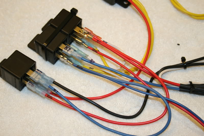
Now take the harness you just made and even up the length of the wires opposite the sockets (where you crimped the 2 wires together onto the 1 wire), now secure 12-gauge .250 Female Spade terminals to the ends of the Red (if you plan to install 3rd. relay also connect the Red #86 relay wire at this time) and the Blue wires.
When you have this done connect them onto the relays,
Blue wire on to the Left hand relay terminal #87.
Red wire on to the Right hand relay terminal #87
Almost there.
Now take 24 inches of 14-12 gauge Red and Blue wire and pair them up, onto one end of both wires secure a 14-12 gauge insulated .250 Female Spade terminal and on the other end secure a .250 Male Spade terminal.
Note: this wire can be as small as 18-gauge as it is only the trigger and carries minimal current.
Connect this wire to the relays,
Blue wire on to the Left hand relay terminal #86. coil + (if you plan to install 3rd. relay also connect the Blue #87 relay wire at this time)
Red wire on to the Right hand relay terminal #86. coil +
This is the trigger wire that will interface the relays to the trucks headlamp circuit.
3rd. Relay is optional; if you are not going to install it you will not make connections to terminals #86 and #87.
The 3rd. relay on the left in the picture gets its trigger from the High Beam relays output Term #87 and latches on, In doing so it supplies power to the Low Beam relay Term. #86 enabling both the High and Low beams to be on at the same time.
An option would be to break the connection of the Red wire between Term. #86 of the optional relay and Term. #87 of the High Beam relay and insert a cab-mounted toggle switch so you can manually choose this option from the drivers seat.

After you have all of the connectors where they belong, take your Sharpie pen and carefully designate the terminal number so if you ever have to replace a relay it will be as easy as reconnecting to the appropriate number.
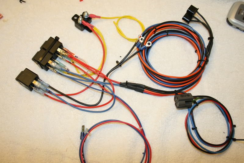
This is what it should look like when you are finished.
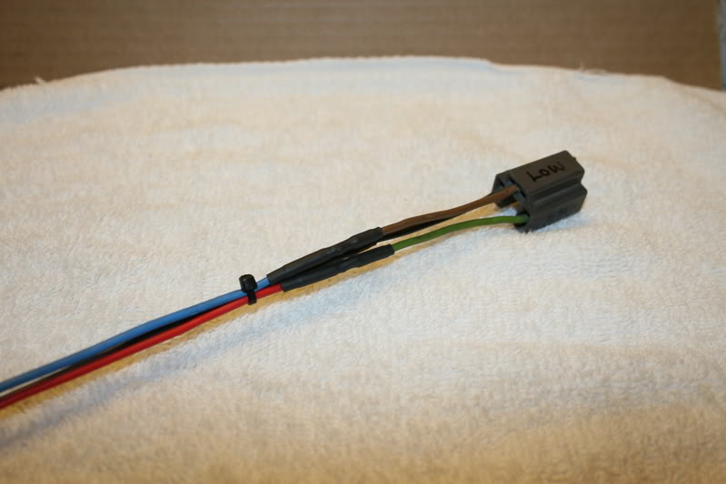
This is how you will connect the trigger wire onto the existing drivers side headlamp socket. Once secure fold it back over the socket and secure it with a Ty-wrap
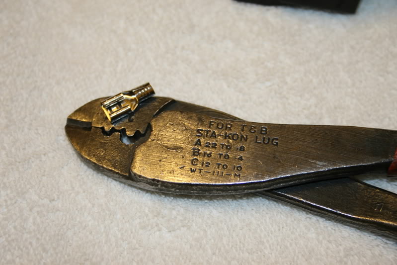
These are the heavy-duty crimpers I use to make the connections with.
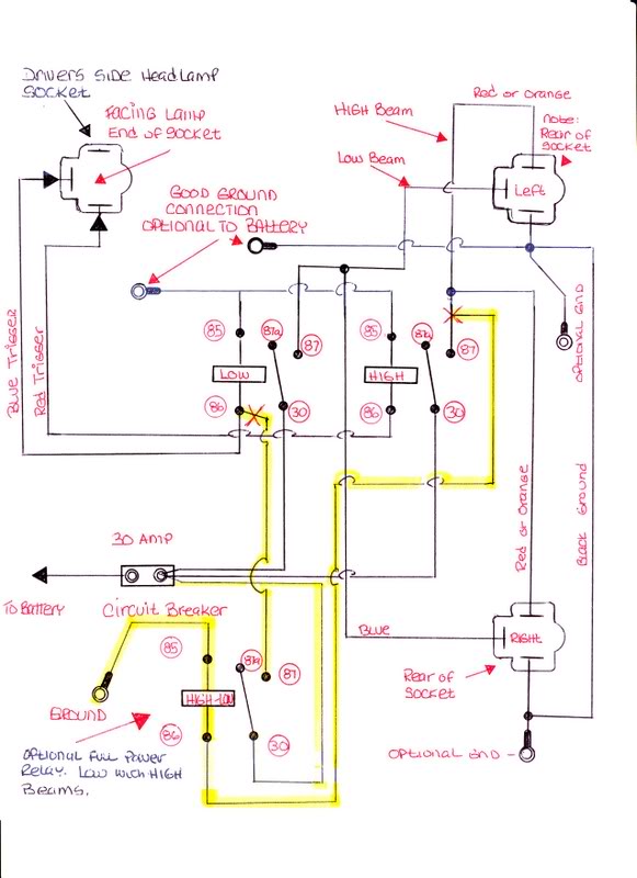
Here is a schematic of what you have just done.
Below are the instructions to add the 3rd. relay to turn on the Low beams in conjunction with the High Beams. You do not have to add this part if you do not want to.
This will simulate you holding back to �flash� when you pull back on the turn signal stalk.
It will burn all filaments at the same time.
You will add the circuit that is highlighted in yellow.
If you wish to add the 3rd. relay to the circuit here is what you will need:
1) 30-amp BOSCH ISO relay.
4) 14 gauge insulated .250 Female Spade terminals.
2) Ring terminal.
Misc wire.
With an approximately 6� length of White or Black wire secure a Ring terminal to one end and secure a insulated .250 Female Spade terminal to the opposite end.
Connect this onto Term. #85 on the relay, this will be the ground connection.
Now with a 6� length of Red wire again secure an insulated .250 Female Spade terminal to one end and connect this to Term. #86 of the relay.
The free end of this wire will connect to Term. #87 of the High Beam (Right side) relay
If you are going to install the 3rd. relay plan to do so while constructing the original circuit.
Insert these 2 wires into the same Female Spade terminal.
Take a length of Red wire and secure a Ring terminal to one end and an insulated .250 Female Spade terminal to the opposite end.
The Female Spade terminal will connect to Term. #30 on the relay and the Ring terminal will get power from the circuit breaker.
Last with a length of Blue wire secure an insulated .250 Female Spade terminal to one end and secure it to Term. #87 on the relay, the free end will connect to Term. #86 on the Low Beam (Left side) relay.
Again using your Sharpie designate all of the terminal numbers for future identification.
When you are finished I would suggest to cover the wiring harness using some split loom to protect it and to make it look professional looking.
When choosing the relays I would use Genuine Bosch or TYCO and not the cheap generic look alikes, there is a big difference and your headlights are critical to have working.
You do not want to take any chances of your headlights going out at any un-opportune moment that could lead to a serious or fatal accident.
I designed this harness for the relays to be mounted on the fender panel next to the battery.
The harness will pass over the core support to the passenger side headlamp.
Trigger wire will connect to the driver�s side headlamp socket.
Driver�s side harness is bundled with the trigger wires.
Mount the circuit breaker close to the battery and connect to the (+) battery feed.
Secure all ground connections under a clean bolt or screw to clean metal.
Here is your parts list again.
2) Premium grade headlight sockets.
2) 30-amp BOSCH ISO relays. Get the genuine thing, more on this.
8) 12-10 gauge uninsulated Butt Splice connectors. (I bought High Temperature connectors from a HVAC supply)
1) 30 amp self-resetting circuit breaker. (Truck Parts of RV supply)
4) 14-12 gauge insulated ring terminals.
2) 14 gauge insulated .250 male spade terminals.
8) 12 gauge insulated .250 female spade connectors. (Home Depot electrical department.)
3) Small rolls of 12 gauge automotive wire; you will need Red, Blue and Black
* * When you buy your terminals try and find a local HVAC warehouse, like Johnstone Supply or Grainger�s. Get the High Temperature terminals, they come in many sizes and are far superior to the ones at your local Auto Parts. Insulate them with Shrink Tubing.
If you are installing 3rd. relay:
1) 30-amp BOSCH ISO relay.
4) 14 gauge Female Spade terminals.
1) Ring terminal.
Misc wire.
Miscellaneous items you will need,
Shrink tubing
Ty-Wraps (zip ties)
Convoluted tubing (Split Loom)
Tools:
Wire cutters.
Good terminal crimpers.
Sharpie marking Pen.
Notes:
Cut yourself a 6� piece of 12 gauge wire and crimp a .250 Male Spade connector on each end.
Stow it away it in your glove box, if your relay ever should fail, connect it to wire terminal #30 and #87 and you will bypass the relay.
Ty-wrap is the same as a Zip-Tie.
This should shed some light on the questions of installing relays.
UPDATE
How to add Low Beam and High Beam control using a diode in place of the third relay.
Yes it can be accomplished very easly by inserting a small signal diode between the Low and High beam relays or it can also be inserted where they connect to the factory harness.
To do this all you need to do is when you are building your harness before you crimp the wires for Term.#86 in addition to the Blue and Red wires insert the leads of a diode with the Anode to the Blue and the Cathode to the Red and then crimp the terminals, when you look at the diode the end with the band is the cathode and is connected to the High Beam Relay.
The theory of operation is simple, when the Low beams are on current is blocked by the diode from flowing to the High beam trigger but when the High beams are on the diode passes current to the Low beam trigger circuit turning on both the High beam and Low beams simultaneously.
LOW~~~~~~~~~~~~~~~~~-HIGH
Term. #86 <------ DIODE------> Term. #86
Remember:
Anode = Blue Wire on the Low beam relay.
Cathode = Red wire on the High beam relay (this is the side with the BAND)
FYI Term. #86 are the 2 vertical terminals on the left side of each relay.
Get your diode from Radio Shack or any electronics supplier; use at least a 2-amp diode for this addition.
Let me know if you have any questions.
Jim
Instructions for optional 3rd. relay are included.
This is how your connections should look as far as we have gone. The White wires are the ground #85 for the coils and the yellow wire supplies the battery power to the armature #30 in the relay.
Now take the harness you just made and even up the length of the wires opposite the sockets (where you crimped the 2 wires together onto the 1 wire), now secure 12-gauge .250 Female Spade terminals to the ends of the Red (if you plan to install 3rd. relay also connect the Red #86 relay wire at this time) and the Blue wires.
When you have this done connect them onto the relays,
Blue wire on to the Left hand relay terminal #87.
Red wire on to the Right hand relay terminal #87
Almost there.
Now take 24 inches of 14-12 gauge Red and Blue wire and pair them up, onto one end of both wires secure a 14-12 gauge insulated .250 Female Spade terminal and on the other end secure a .250 Male Spade terminal.
Note: this wire can be as small as 18-gauge as it is only the trigger and carries minimal current.
Connect this wire to the relays,
Blue wire on to the Left hand relay terminal #86. coil + (if you plan to install 3rd. relay also connect the Blue #87 relay wire at this time)
Red wire on to the Right hand relay terminal #86. coil +
This is the trigger wire that will interface the relays to the trucks headlamp circuit.
3rd. Relay is optional; if you are not going to install it you will not make connections to terminals #86 and #87.
The 3rd. relay on the left in the picture gets its trigger from the High Beam relays output Term #87 and latches on, In doing so it supplies power to the Low Beam relay Term. #86 enabling both the High and Low beams to be on at the same time.
An option would be to break the connection of the Red wire between Term. #86 of the optional relay and Term. #87 of the High Beam relay and insert a cab-mounted toggle switch so you can manually choose this option from the drivers seat.
After you have all of the connectors where they belong, take your Sharpie pen and carefully designate the terminal number so if you ever have to replace a relay it will be as easy as reconnecting to the appropriate number.
This is what it should look like when you are finished.
This is how you will connect the trigger wire onto the existing drivers side headlamp socket. Once secure fold it back over the socket and secure it with a Ty-wrap
These are the heavy-duty crimpers I use to make the connections with.
Here is a schematic of what you have just done.
Below are the instructions to add the 3rd. relay to turn on the Low beams in conjunction with the High Beams. You do not have to add this part if you do not want to.
This will simulate you holding back to �flash� when you pull back on the turn signal stalk.
It will burn all filaments at the same time.
You will add the circuit that is highlighted in yellow.
If you wish to add the 3rd. relay to the circuit here is what you will need:
1) 30-amp BOSCH ISO relay.
4) 14 gauge insulated .250 Female Spade terminals.
2) Ring terminal.
Misc wire.
With an approximately 6� length of White or Black wire secure a Ring terminal to one end and secure a insulated .250 Female Spade terminal to the opposite end.
Connect this onto Term. #85 on the relay, this will be the ground connection.
Now with a 6� length of Red wire again secure an insulated .250 Female Spade terminal to one end and connect this to Term. #86 of the relay.
The free end of this wire will connect to Term. #87 of the High Beam (Right side) relay
If you are going to install the 3rd. relay plan to do so while constructing the original circuit.
Insert these 2 wires into the same Female Spade terminal.
Take a length of Red wire and secure a Ring terminal to one end and an insulated .250 Female Spade terminal to the opposite end.
The Female Spade terminal will connect to Term. #30 on the relay and the Ring terminal will get power from the circuit breaker.
Last with a length of Blue wire secure an insulated .250 Female Spade terminal to one end and secure it to Term. #87 on the relay, the free end will connect to Term. #86 on the Low Beam (Left side) relay.
Again using your Sharpie designate all of the terminal numbers for future identification.
When you are finished I would suggest to cover the wiring harness using some split loom to protect it and to make it look professional looking.
When choosing the relays I would use Genuine Bosch or TYCO and not the cheap generic look alikes, there is a big difference and your headlights are critical to have working.
You do not want to take any chances of your headlights going out at any un-opportune moment that could lead to a serious or fatal accident.
I designed this harness for the relays to be mounted on the fender panel next to the battery.
The harness will pass over the core support to the passenger side headlamp.
Trigger wire will connect to the driver�s side headlamp socket.
Driver�s side harness is bundled with the trigger wires.
Mount the circuit breaker close to the battery and connect to the (+) battery feed.
Secure all ground connections under a clean bolt or screw to clean metal.
Here is your parts list again.
2) Premium grade headlight sockets.
2) 30-amp BOSCH ISO relays. Get the genuine thing, more on this.
8) 12-10 gauge uninsulated Butt Splice connectors. (I bought High Temperature connectors from a HVAC supply)
1) 30 amp self-resetting circuit breaker. (Truck Parts of RV supply)
4) 14-12 gauge insulated ring terminals.
2) 14 gauge insulated .250 male spade terminals.
8) 12 gauge insulated .250 female spade connectors. (Home Depot electrical department.)
3) Small rolls of 12 gauge automotive wire; you will need Red, Blue and Black
* * When you buy your terminals try and find a local HVAC warehouse, like Johnstone Supply or Grainger�s. Get the High Temperature terminals, they come in many sizes and are far superior to the ones at your local Auto Parts. Insulate them with Shrink Tubing.
If you are installing 3rd. relay:
1) 30-amp BOSCH ISO relay.
4) 14 gauge Female Spade terminals.
1) Ring terminal.
Misc wire.
Miscellaneous items you will need,
Shrink tubing
Ty-Wraps (zip ties)
Convoluted tubing (Split Loom)
Tools:
Wire cutters.
Good terminal crimpers.
Sharpie marking Pen.
Notes:
Cut yourself a 6� piece of 12 gauge wire and crimp a .250 Male Spade connector on each end.
Stow it away it in your glove box, if your relay ever should fail, connect it to wire terminal #30 and #87 and you will bypass the relay.
Ty-wrap is the same as a Zip-Tie.
This should shed some light on the questions of installing relays.
UPDATE
How to add Low Beam and High Beam control using a diode in place of the third relay.
Yes it can be accomplished very easly by inserting a small signal diode between the Low and High beam relays or it can also be inserted where they connect to the factory harness.
To do this all you need to do is when you are building your harness before you crimp the wires for Term.#86 in addition to the Blue and Red wires insert the leads of a diode with the Anode to the Blue and the Cathode to the Red and then crimp the terminals, when you look at the diode the end with the band is the cathode and is connected to the High Beam Relay.
The theory of operation is simple, when the Low beams are on current is blocked by the diode from flowing to the High beam trigger but when the High beams are on the diode passes current to the Low beam trigger circuit turning on both the High beam and Low beams simultaneously.
LOW~~~~~~~~~~~~~~~~~-HIGH
Term. #86 <------ DIODE------> Term. #86
Remember:
Anode = Blue Wire on the Low beam relay.
Cathode = Red wire on the High beam relay (this is the side with the BAND)
FYI Term. #86 are the 2 vertical terminals on the left side of each relay.
Get your diode from Radio Shack or any electronics supplier; use at least a 2-amp diode for this addition.
Let me know if you have any questions.
Jim

Registered User


Joined: Oct 2005
Posts: 6,457
Likes: 95
From: KENTUCKY
Excellent and needed write-up for those that were a bit over-whelmed.
Good job !!
I used genuine RELAY PIGTAILS, should I have a relay to fail, I simply un-plug the old and plug in the new; these aren't easy to find, especially in the larger wire gauges; but, the smaller gauge ones can be dis-assembled and larger gauge wire installed.
Also, an extra un-used relay can be mounted beside the others, with it's terminal prongs protected from dirt in some creative way; so that, should a relay fail, it can be quickly replaced by simply un-plugging from the bad and re-plugging to the good; and, you don't have to wonder where you put that extra emergency relay, as it's hanging right there beside the rest of them.
This third relay's TRIGGER/SWITCH wire can be routed through a dash-mounted switch, such that the both-beams-on feature can be selected at will.
Good job !!
I used genuine RELAY PIGTAILS, should I have a relay to fail, I simply un-plug the old and plug in the new; these aren't easy to find, especially in the larger wire gauges; but, the smaller gauge ones can be dis-assembled and larger gauge wire installed.
Also, an extra un-used relay can be mounted beside the others, with it's terminal prongs protected from dirt in some creative way; so that, should a relay fail, it can be quickly replaced by simply un-plugging from the bad and re-plugging to the good; and, you don't have to wonder where you put that extra emergency relay, as it's hanging right there beside the rest of them.
You will see I have also included a 3rd. relay to turn on the Low beams in conjunction with the High Beams.
It will burn all filaments at the same time.
It will burn all filaments at the same time.
This third relay's TRIGGER/SWITCH wire can be routed through a dash-mounted switch, such that the both-beams-on feature can be selected at will.

Registered User
Joined: Oct 2005
Posts: 6,457
Likes: 95
From: KENTUCKY
I bought mine at my local truck parts as seen to the right of the cheap one; they are made by Cole Hersee
http://www.colehersee.com/catalog_top/index.htm
And are used on OTR tractors and other heavy equipment.

Here you can see the difference in the size of the wire. They look to be 18-gauge wire but since they are from China they would be a metric equivalent.
The ones on my socket are 14-gauge and as you can see quite a bit heavier.
http://www.colehersee.com/catalog_top/index.htm
And are used on OTR tractors and other heavy equipment.
Here you can see the difference in the size of the wire. They look to be 18-gauge wire but since they are from China they would be a metric equivalent.
The ones on my socket are 14-gauge and as you can see quite a bit heavier.
Those look to be exactly the same ones that I got at the local NAPA.
NAPA/ECHLIN part-number = LS6235
heat it with a heat gun or carefully use a cigarette lighter to shrink the tubing to the wire and seal it tight.
Of course if you used regular insulated Butt Splice connectors you will have a lump on each wire, but that is OK.
On the end of the pigtail provide a ring terminal, this will be a Ground connection.
you could use Black wire but it should not be Red or Blue for ease of identifying the circuit after it is installed. It is just easier to diagnose later on. If there is ever a problem.
you could use Black wire but it should not be Red or Blue for ease of identifying the circuit after it is installed. It is just easier to diagnose later on. If there is ever a problem.
In order to keep myself from getting confused (easier done than one would think
 ), I try to always use GReen for GRound; of course, I get into these weekend-everything-closed-don't-want-to-go-to-town projects and everything gets wired with whatever color wire happens to be available.
Excellent write-up, JIM.
Trending Topics


Registered User
Joined: Dec 2006
Posts: 398
Likes: 0
From: Tennessee
well just did this, took about an hour, all i need to do is change the pigtails. i did the rest just hacking into the stock wiring, everything is wired with 10gauge wire, hopefully the pigtails will help some more

