
Ign switch


Thread Starter
Registered User
Joined: Dec 2007
Posts: 58
Likes: 0
Ign switch
Hi guys, I post very seldom but I do read what you guys are doing to your trucks. I am not hopping mine up as I am pretty well pleased with what it does also I don't like working on them.
I do machining and welding but I don't do much welding any more due to tremors.
Some time back one of you posted a thread on how to get rid of some of the load on the ign switch by using relays and feeding the relay through the ign sw.
I have found the sticky on headlight relays, is that the one that I want to read and follow to get some of the electrical load off of the ign sw?
At this point the only problem that I have had is the dash light and hazard blinkers will start flashing also under the ign. sw gets warm to the touch.
My truck is a 93 LE with 92000 + on the clock, when I purchased the truck 5 years ago, at that time it had 52000+.
I paid $7K for it at that time from an estate and believe that I got a darn good deal, especially when I see what you guys pay for yours.
DTR's "Cooler than ice cubes 14 miles North of North Pole" member
Joined: Oct 2006
Posts: 1,797
Likes: 9
From: 14mi North of North Pole
Look through Jim Lane's threads.
https://www.dieseltruckresource.com/...archid=3685816
He does some AWSOME electrical work. He is also most likley the author of the post you came across detailing moving the load off the ignition switch.
https://www.dieseltruckresource.com/...archid=3685816
He does some AWSOME electrical work. He is also most likley the author of the post you came across detailing moving the load off the ignition switch.

Administrator


Joined: Nov 2004
Posts: 4,084
Likes: 235
From: Southern California
Look through Jim Lane's threads.
https://www.dieseltruckresource.com/...archid=3685816
He does some AWSOME electrical work. He is also most likley the author of the post you came across detailing moving the load off the ignition switch.
https://www.dieseltruckresource.com/...archid=3685816
He does some AWSOME electrical work. He is also most likley the author of the post you came across detailing moving the load off the ignition switch.
I am sure it was me that had made some mention of it in one of my post, I think the Blower Motor on Relays was one of them.
https://www.dieseltruckresource.com/...d.php?t=158400
Yes after my fan motor had caused the wiring to my ignition switch to burn up and melted my ignition switch the first the first order of business was to find a way to take all load of the ignition switched circuits in the fuse panel off the switch and control them remotely with a relay.
But sorry to say that I have not done a write-ups for this as of yet but I will put this request on the top of my list.
Jim
DTR's "Cooler than ice cubes 14 miles North of North Pole" member
Joined: Oct 2006
Posts: 1,797
Likes: 9
From: 14mi North of North Pole
Credit where credit is due.
I think you're just dong it 1 circuit at a time throughout all you various write-ups.
Thread Starter
Registered User
Joined: Dec 2007
Posts: 58
Likes: 0
Thanks for your replys guys.
I just found a thread where Jim made a modification to a modification.
I will get these out and do some studying as this is something that I feel needs to be done. My neighbor has a first generation 1991 auto, he has had to replace the ign sw a couple of times and as I said mine gets warm.
I just found a thread where Jim made a modification to a modification.
I will get these out and do some studying as this is something that I feel needs to be done. My neighbor has a first generation 1991 auto, he has had to replace the ign sw a couple of times and as I said mine gets warm.
Thread Starter
Registered User
Joined: Dec 2007
Posts: 58
Likes: 0
Jim Lane
Jim, I have studied you modification on the blower motor and it is great. Now here come the questions. My main concern is getting the load off of the ignition switch.
I don't have a manual for this truck so the questions.
It took me a while to get back to this as we had company and another project got in the way.
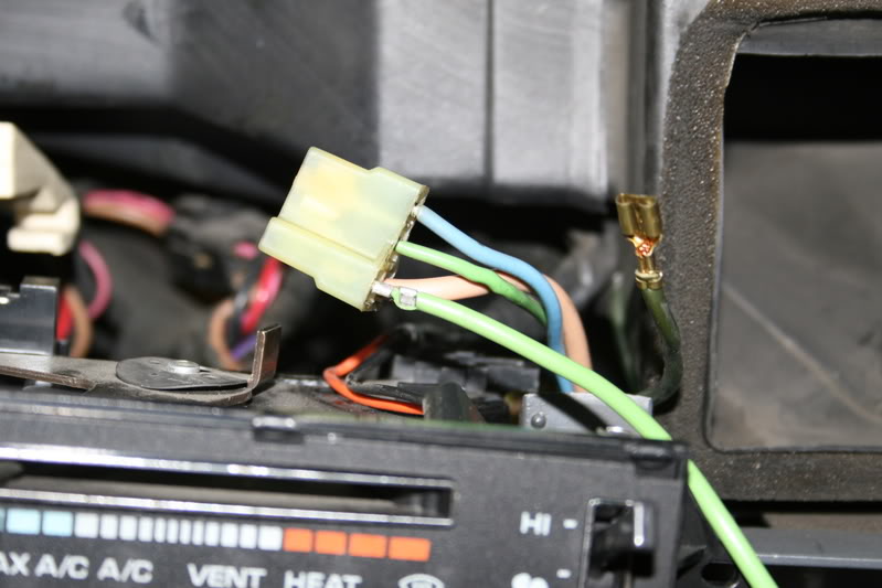
1-What is the plug that I have circled in black and where is it located? I think it is probably in the duct work some where.
2-The one that is circled in red is probably just ahead of the blower motor. Is this correct.
3- the block that I have circled in blue is this block the main fuse block or is it some where else. I would think that fuse would come in ahead of the ignition switch. My thoughts are to cut in on 020 with the relay feeding the relay directly off of the battery and use Q20 to close the relay. It may be better to install the relay on the load side of the fuse and feed the relay directly from the batt and the fuse to circuit to close the relay.
I really appreciate any help.
I don't have a manual for this truck so the questions.
It took me a while to get back to this as we had company and another project got in the way.
1-What is the plug that I have circled in black and where is it located? I think it is probably in the duct work some where.
2-The one that is circled in red is probably just ahead of the blower motor. Is this correct.
3- the block that I have circled in blue is this block the main fuse block or is it some where else. I would think that fuse would come in ahead of the ignition switch. My thoughts are to cut in on 020 with the relay feeding the relay directly off of the battery and use Q20 to close the relay. It may be better to install the relay on the load side of the fuse and feed the relay directly from the batt and the fuse to circuit to close the relay.
I really appreciate any help.
Administrator
Joined: Nov 2004
Posts: 4,084
Likes: 235
From: Southern California
Jim, I have studied you modification on the blower motor and it is great. Now here come the questions. My main concern is getting the load off of the ignition switch.
I don't have a manual for this truck so the questions.
It took me a while to get back to this as we had company and another project got in the way.
1-What is the plug that I have circled in black and where is it located? I think it is probably in the duct work some where.
The connector circled in BLACK is in the engine compartment and is about 8 inches from the blower motor.
2-The one that is circled in red is probably just ahead of the blower motor. Is this correct.
The connector circled in RED is behind the dash and is directly above the heater controls, you need to remove the trim to get to it.

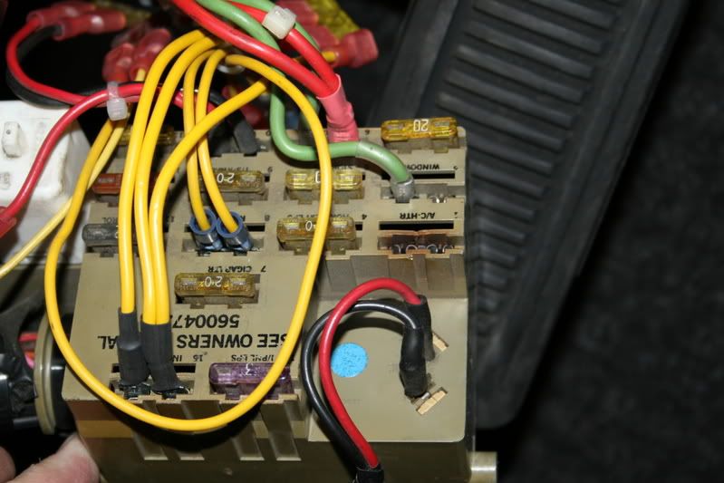
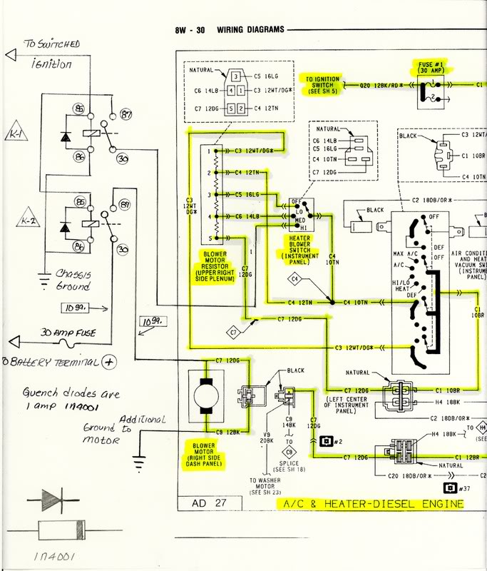
3- the block that I have circled in blue is this block the main fuse block or is it some where else. I would think that fuse would come in ahead of the ignition switch. My thoughts are to cut in on 020 with the relay feeding the relay directly off of the battery and use Q20 to close the relay. It may be better to install the relay on the load side of the fuse and feed the relay directly from the batt and the fuse to circuit to close the relay.
Yes this is the main Fuse Panel.
I really appreciate any help.
I don't have a manual for this truck so the questions.
It took me a while to get back to this as we had company and another project got in the way.
1-What is the plug that I have circled in black and where is it located? I think it is probably in the duct work some where.
The connector circled in BLACK is in the engine compartment and is about 8 inches from the blower motor.
2-The one that is circled in red is probably just ahead of the blower motor. Is this correct.
The connector circled in RED is behind the dash and is directly above the heater controls, you need to remove the trim to get to it.
3- the block that I have circled in blue is this block the main fuse block or is it some where else. I would think that fuse would come in ahead of the ignition switch. My thoughts are to cut in on 020 with the relay feeding the relay directly off of the battery and use Q20 to close the relay. It may be better to install the relay on the load side of the fuse and feed the relay directly from the batt and the fuse to circuit to close the relay.
Yes this is the main Fuse Panel.
I really appreciate any help.
This modification only removes a partial load from the Fuse Panel and was not meant to remove loads from the ignition switch, it was assumed to be already controlled by a relay.
But again, I have not done a write-ups for this as of yet but I will put this request on the top of my list.
Jim
Trending Topics
Thread Starter
Registered User
Joined: Dec 2007
Posts: 58
Likes: 0
Jim thanks for the reply, I understand that. I now have a question about how the power is supplied to the fuse.
Does the power come from the Batt to the ign sw than to the fuse block or is there some connection that is not shown on the schematic that you have posted here?
This sketch is what I am thinking about, Jim. That is if it makes sense and will work.
Does the power come from the Batt to the ign sw than to the fuse block or is there some connection that is not shown on the schematic that you have posted here?
This sketch is what I am thinking about, Jim. That is if it makes sense and will work.
Administrator
Joined: Nov 2004
Posts: 4,084
Likes: 235
From: Southern California
Jim thanks for the reply, I understand that. I now have a question about how the power is supplied to the fuse.
Does the power come from the Batt to the ign sw than to the fuse block or is there some connection that is not shown on the schematic that you have posted here?
This sketch is what I am thinking about, Jim. That is if it makes sense and will work.
Does the power come from the Batt to the ign sw than to the fuse block or is there some connection that is not shown on the schematic that you have posted here?
This sketch is what I am thinking about, Jim. That is if it makes sense and will work.
Blower Motor Fuse #1 & #2 get their voltage directly from the ignition switch over the 12-gauge BK/RD wire Q20 at terminal A-2 on the switch.
The switch then gets its voltage through terminal B-3 on the switch from wire J10 12-gauge PK that enters the engine compartment on the driver�s side and terminates in a Fuse Link that is eventually connected into the 6-gauge wire from the alternators output.

Here is how I would connect the relay,
Term.#85 to Ground.
Term.#86 to the 12-gauge BK/RD wire that you remove from the #1 & #2 fuse feed, this is the 16-gauge signal wire that has the clear insulator over it. Ignition now triggers the relay coil.
Term.#30 connect at least an 8-gauge wire from this terminal through the firewall and at the end connect a fuse link appropriate for 40-amps and the opposite end to the battery (+)
Term #87 connect another length of 8-gauge wire with the opposite end connected to the back of the fuse panel feed for fuse #1 & #2 see the wire with the red heat shrink.
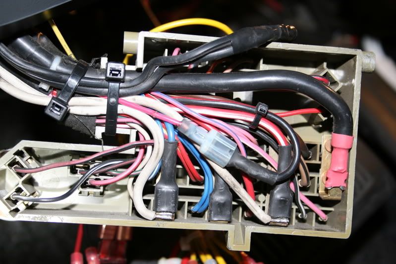
Use enough 8-gauge wire and secure it into the harness so the fuse panel can be installed back into its location, mount the relay under the dash with enough wire so it can be easly dropped down if you should need to replace the relay.
You should use a relay capable of carrying enough current, a 30/40-amp relay should work if you do not have a lot of accessories, I use a 75-amp relay on mine.
Use good quality female spade terminals that are capable of carrying the current of the wire. I use High Temperature terminals used for appliances and HVAC; you can get then at most HVAC suppliers and Grainger�s.
Hope this helps.
Jim
Thread Starter
Registered User
Joined: Dec 2007
Posts: 58
Likes: 0
Jim, do you have the schematic for the ignition sw. and the associated wiring? Or is it posted some where on here?
I did a search for electrical schematic and electrical diagram and did not turn up anything.
Thanks, I really appreciate your help, Jim.
Charlie.
I did a search for electrical schematic and electrical diagram and did not turn up anything.
Thanks, I really appreciate your help, Jim.
Charlie.
Thread Starter
Registered User
Joined: Dec 2007
Posts: 58
Likes: 0
Hay Guys where is the best place to purchase the relays that Jim is recommending?
I have found several sites but there is quite a range in prices and they are not familiar places that I really want to take a wild chance on.
Got the truck in the shop so in the morning I will have a nice warm truck to work on.
I have found several sites but there is quite a range in prices and they are not familiar places that I really want to take a wild chance on.
Got the truck in the shop so in the morning I will have a nice warm truck to work on.
Registered User
Joined: Nov 2006
Posts: 268
Likes: 0
From: Lincoln,NE
I think someone already tried to ask a back-feed question earlier in class but it was maybe misunderstood...
My question is does the 12V from the "high relay" get wired right into the positive from the resistor block (DG)?? If so does the voltage from the 3 lower speeds back feed into the relay?
I've always had the idea to do it this way but figured the lower speeds would energize the relay when they were on.
Is this right??
Administrator
Joined: Nov 2004
Posts: 4,084
Likes: 235
From: Southern California
Hay Guys where is the best place to purchase the relays that Jim is recommending?
I have found several sites but there is quite a range in prices and they are not familiar places that I really want to take a wild chance on.
Got the truck in the shop so in the morning I will have a nice warm truck to work on.
I have found several sites but there is quite a range in prices and they are not familiar places that I really want to take a wild chance on.
Got the truck in the shop so in the morning I will have a nice warm truck to work on.
If you have some locally check your local Heavy Truck Parts, I just bought 3 Tyco Relays for $3.25 each Mounting sockets with 10-gauge leads were $5.00 each however 75-amp units were up to $45.00 each, I got it for $35.00.
Also after you have them installed, run the blower on High for about 10 minuets and then check the relay and wiring and check to see if they are excessively hot to the touch, if they are it is recommended to step up the smaller 70-amp unit or the 75-amp power relay like I did. It doesn't even get warm and it its contacts are designed to suppress arcing due to inductive loads.
Also do not be tempted to buy cheap generic relays sold at auto parts for fog lights, they are grossly inferior and will burn out in a short time.
Jim
Administrator
Joined: Nov 2004
Posts: 4,084
Likes: 235
From: Southern California
I think someone already tried to ask a back-feed question earlier in class but it was maybe misunderstood...
My question is does the 12V from the "high relay" get wired right into the positive from the resistor block (DG)?? If so does the voltage from the 3 lower speeds back feed into the relay?
I've always had the idea to do it this way but figured the lower speeds would energize the relay when they were on.
Is this right??
No,
If you were to connect the relay into the DG wire at the blower motor you would have no speeds other than High, also without knowing where the rest of your wires go but I assume Battery and Blower Motor, once the blower was turned on it would not turn off until the Relay Term #86 was interrupted the reason is once the power is turned OFF the motor will become a generator and supply the relay coil with the voltage to keep the relay pulled in while in turn applying full power to the motor.
Here you can see how I had to modify the blower speed switch wiring, the empty cavity in the lower left is the High Speed, and I disconnect the lead from the switch to the resistor block.
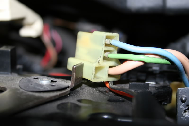
Here you can see how I connected my new connection from the Blower Speed High and it will now connect to the Common Term. #30 of the Anti-Feedback relay K-1.
Once the IGN is tuned ON the coil will close the contacts and energize the Power Relay K-2 connecting the Battery power directly to the Blower Motor.
The feedback from the motor is interrupted as soon as the IGN is turned OFF breaking the circuit to the Power Relay.
It is really quits simple, I could have solved the problem with a few freewheeling diodes but the Blower Motor is a PM field and generates quite a bit of current as a generator, using a relay is a lot simpler.
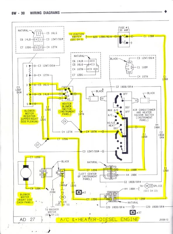
Unmodified drawing.
I hope this explains why I did it this way, any other questions feel free to ask.
Also some people seem to overlook that that the Blower Motor connector C-9 the new the heavy gauge wire from the power relay must be connecter to the motor along with the factory circuit or you will only have High Speed.
Make sure that you also provide a new heavy gauge Ground wire at the motor or you will have wasted your time adding all of the relays.
Jim