
Head Stud Install Primer

Thread Starter
1st Generation Admin
Joined: Jan 2005
Posts: 4,601
Likes: 118
From: Buies Creek, NC
Folks, this thread is intended to be a general overview of the typical steps of installing head studs in the 12 valve Cummins engine. It is by NO means the authoritative "How To" for doing such. This thread is based solely on my experience working with my '93 Cummins 5.9. Another truck's mileage may vary.
It is assumed that you know the business end of a wrench and will be following all standard recommended safety practices including safety glasses, chocked wheels, disconnected battery, fire extinguisher, etc.
In this instance, I'm installing the regular, high-strength studs as provided by Haisley Machine using A1 Technologies components. Many use those from ARP with equal results in my opinion. NOTE: This thread is not for debating which brand is better. Thanks.
One of the more dominant reasons for installing head studs is to help ensure the head gasket's integrity when running with higher than stock boost, water/methanol, nitrous oxide, etc. The benefits include a higher than OEM clamping force to help ensure the head gasket's fire-ring isn't pushed aside thus blowing the gasket out of place.
Again, assuming one knows the business end of a wrench, we're gonna fast forward through the removal of the engine's cylinder head. Suffice it to say that one needs to remove:
- The valve covers, rocker-arm assemblies with the associated pedestals, and push-rods.
- The turbocharger(s) and exhaust manifold.
- The charge-air intake plumbing.
- The high-pressure fuel injector lines, injector fuel return line, and injectors. NOTE, it is strongly recommended that one remove the injectors so as not to damage the tips while moving the head around.
- The alternator, all wiring harnesses, coolant plumbing, throttle linkage bracket, and anything else I've forgotten.
- The remaining head bolts. Technically speaking, the FSM presents a recommended sequence for loosening the bolts. I confess I didn't go by it.
To help me keep up with what went where, I put each rocker/pedestal assembly in it's own numbered zip-lock bag. Further, I punched some holes in some scrap cardboard, and labeled each hole for the push-rods as removed from the engine.

BE SURE to look all the way around the head making sure you/I haven't missed anything. Not sure? Check again.
As far as lifting the head from the block, I found it best to remove the hood and lift the head with my tractor and a boom. There are those who've used personal brute strength to lift the head but my back ain't into it. The head weighs well over 100 pounds so be careful and keep up with your fingers.
Be aware that there are two small cylindrical shaped sleeves that are used to locate the head, block and gasket. Don't loose them as you remove the head.
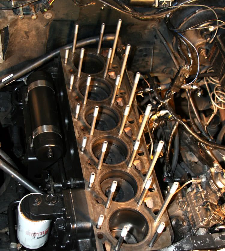
OK, so now we've got the head off. At this point, you'll need to go about cleaning the surfaces of both the head and block's mating surfaces.
I used wads of paper towels to plug those holes in the deck that are open to the block's internals so as not to get any trash in there.
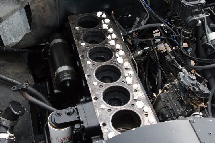
I used a putty-knife to scrape the big stuff off followed by a Scotch-Brite pad with some WD40 as a lubricant/solvent. There's no need in scrubbing things to remove any staining of the surfaces. We certainly don't want to remove the subtle ridges of the surfaces as they may very well be a part of the "Bond" of the assembled product.

OK, let's get on with installing the studs.
As I see it, no one makes studs specifically for the CTD. With that, those available amount to a close fit. Those available are such that, in this case, the studs are too long to use in the OEM block without subtle modification of the block (Bottom-Tapping). Another brand may be a bit too short and require milling of the rocker arm pedestals so as to allow full engagement of the threads of the associated nuts. The later may have changed, I don't know. Do your homework.
The studs I used require Bottom-Tapping of the block's threads to allow the stud to be fully seated in the block. This will in many cases allow the studs to not interfere with the valve covers being fully seated on reassembly. Still, some grinding of the valve cover's internal webbing may be required to clear the studs.
I've read where a few consumers don't advocate bottom-tapping as they had issues with installing the studs afterward. I can't help but believe they did something incorrectly.
Regardless, a minimum of chasing the block's threads assures clean threads as the overall strength of the stud assembly depends on a clean, uniform engagement of the thread interface. READ, UNDERSTAND, and FOLLOW the instructions provided with your product. If you're not sure, call the manufacturer.
It is assumed that you know the business end of a wrench and will be following all standard recommended safety practices including safety glasses, chocked wheels, disconnected battery, fire extinguisher, etc.
In this instance, I'm installing the regular, high-strength studs as provided by Haisley Machine using A1 Technologies components. Many use those from ARP with equal results in my opinion. NOTE: This thread is not for debating which brand is better. Thanks.
One of the more dominant reasons for installing head studs is to help ensure the head gasket's integrity when running with higher than stock boost, water/methanol, nitrous oxide, etc. The benefits include a higher than OEM clamping force to help ensure the head gasket's fire-ring isn't pushed aside thus blowing the gasket out of place.
Again, assuming one knows the business end of a wrench, we're gonna fast forward through the removal of the engine's cylinder head. Suffice it to say that one needs to remove:
- The valve covers, rocker-arm assemblies with the associated pedestals, and push-rods.
- The turbocharger(s) and exhaust manifold.
- The charge-air intake plumbing.
- The high-pressure fuel injector lines, injector fuel return line, and injectors. NOTE, it is strongly recommended that one remove the injectors so as not to damage the tips while moving the head around.
- The alternator, all wiring harnesses, coolant plumbing, throttle linkage bracket, and anything else I've forgotten.
- The remaining head bolts. Technically speaking, the FSM presents a recommended sequence for loosening the bolts. I confess I didn't go by it.
To help me keep up with what went where, I put each rocker/pedestal assembly in it's own numbered zip-lock bag. Further, I punched some holes in some scrap cardboard, and labeled each hole for the push-rods as removed from the engine.
BE SURE to look all the way around the head making sure you/I haven't missed anything. Not sure? Check again.
As far as lifting the head from the block, I found it best to remove the hood and lift the head with my tractor and a boom. There are those who've used personal brute strength to lift the head but my back ain't into it. The head weighs well over 100 pounds so be careful and keep up with your fingers.
Be aware that there are two small cylindrical shaped sleeves that are used to locate the head, block and gasket. Don't loose them as you remove the head.
OK, so now we've got the head off. At this point, you'll need to go about cleaning the surfaces of both the head and block's mating surfaces.
I used wads of paper towels to plug those holes in the deck that are open to the block's internals so as not to get any trash in there.
I used a putty-knife to scrape the big stuff off followed by a Scotch-Brite pad with some WD40 as a lubricant/solvent. There's no need in scrubbing things to remove any staining of the surfaces. We certainly don't want to remove the subtle ridges of the surfaces as they may very well be a part of the "Bond" of the assembled product.
OK, let's get on with installing the studs.
As I see it, no one makes studs specifically for the CTD. With that, those available amount to a close fit. Those available are such that, in this case, the studs are too long to use in the OEM block without subtle modification of the block (Bottom-Tapping). Another brand may be a bit too short and require milling of the rocker arm pedestals so as to allow full engagement of the threads of the associated nuts. The later may have changed, I don't know. Do your homework.
The studs I used require Bottom-Tapping of the block's threads to allow the stud to be fully seated in the block. This will in many cases allow the studs to not interfere with the valve covers being fully seated on reassembly. Still, some grinding of the valve cover's internal webbing may be required to clear the studs.
I've read where a few consumers don't advocate bottom-tapping as they had issues with installing the studs afterward. I can't help but believe they did something incorrectly.
Regardless, a minimum of chasing the block's threads assures clean threads as the overall strength of the stud assembly depends on a clean, uniform engagement of the thread interface. READ, UNDERSTAND, and FOLLOW the instructions provided with your product. If you're not sure, call the manufacturer.
Thread Starter
1st Generation Admin
Joined: Jan 2005
Posts: 4,601
Likes: 118
From: Buies Creek, NC
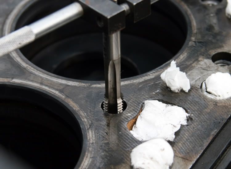
The tap I used was from WW Granger's. It's the standard high-strength steel variety. The typical bottoming tap is designed such that only the first couple or three threads are tapered as compared to a regular tap. The following image clearly illustrates the differences between a bottoming tap, and a standard tap.
The correct size to do our work is M12x1.75.
The task is pretty much straight forward. Insert the tap being sure not to get it cross-threaded. If your mess is like mine, you'll feel the carbon build-up being cut from the threads as you screw the tap in. As you reach the bottom of the bore, you'll feel an increase in the resistance to turn. This is where you're cutting the metal left by the original standard thread tap. It wouldn't hurt to squirt some WD40 in there so as to help the tap cut cleanly. It's usually best to turn the tap about a full turn, then back it out a little and then go in deeper another full turn. It gets kinda tight to turn as you reach the bottom of the bore so don't get so carried away that you break the tap trying to screw through the bottom of the bore.
To ensure a clean cut thread, I ran the tap in and out, cleaning the accumulated metal shavings and carbon from the tap's flutes with each pass.

I made repeated passes so that I was eventually able to run the tap in and out using only one finger to spin the tap's handle.
Now we need to clean things up. Seeing as the holes are kinda deep in the block, it's at best difficult to get all the mess out. I found it most effective to use a vacuum hose set off to the side of a given bolt hole. Place the vacuum hose flat on the head so that any air moving into the hose, has to go through the hole first. Make it whistle. I then flushed the hole out using some common aerosol NON-FLAMMABLE brake cleaner having the accessory little tube extension to get to the very bottom of the hole. With the vacuum running, squirt the cleaner from the bottom of the hole, letting it and any debre be sucked out with the vacuum.
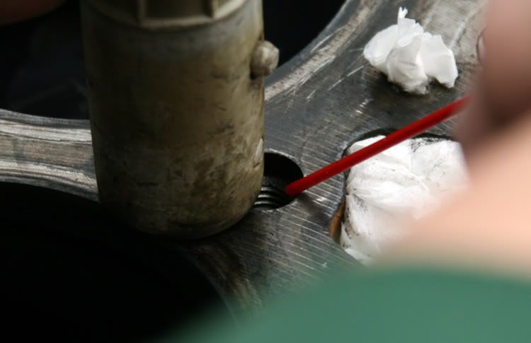
WARNING, WARNING, WARNING! Do not use a flammable cleaner for this as the electric motor of the vacuum may ignite the solvent with severe consequences to you and the truck. It's no way to get out of cutting the grass!
OK, to make a final check of your work, dry fit the studs in the block being sure they fully seat in the bottom of the bore.
Now remove all the studs and begin the task of reinstalling the head following standard procedure for doing such. Clean, clean, clean. I put those two locating sleeves in the block to help hold the new head gasket in place. If your head has O-rings, be very careful in placing the head, not allowing it to drag about damaging the O-rings.
With the head in place, we can now start reassembling things.
- Reinstall the valve train push rods ensuring that they are fully seated in the lifter. Don't let them fool you and have one sitting out of the lifter. It'll come back to bite you later.
- Reinstall the rocker arm pedestals holding them in place with the smaller bolts just snugged.
With that, we'll install the studs themselves. Lubricate the studs with a light coat of regular engine oil, not the ARP assembly lube. Screw them into the block all the way HAND TIGHT and no more. Be sure they are fully seated in the bores. Again, hand tight only.
Now we'll install the stud washers and nuts. No weird science here, but we do want to liberally pre-lubricate the the studs, washers and nuts using ARP assembly lube.

The correct size to do our work is M12x1.75.
The task is pretty much straight forward. Insert the tap being sure not to get it cross-threaded. If your mess is like mine, you'll feel the carbon build-up being cut from the threads as you screw the tap in. As you reach the bottom of the bore, you'll feel an increase in the resistance to turn. This is where you're cutting the metal left by the original standard thread tap. It wouldn't hurt to squirt some WD40 in there so as to help the tap cut cleanly. It's usually best to turn the tap about a full turn, then back it out a little and then go in deeper another full turn. It gets kinda tight to turn as you reach the bottom of the bore so don't get so carried away that you break the tap trying to screw through the bottom of the bore.
To ensure a clean cut thread, I ran the tap in and out, cleaning the accumulated metal shavings and carbon from the tap's flutes with each pass.
I made repeated passes so that I was eventually able to run the tap in and out using only one finger to spin the tap's handle.
Now we need to clean things up. Seeing as the holes are kinda deep in the block, it's at best difficult to get all the mess out. I found it most effective to use a vacuum hose set off to the side of a given bolt hole. Place the vacuum hose flat on the head so that any air moving into the hose, has to go through the hole first. Make it whistle. I then flushed the hole out using some common aerosol NON-FLAMMABLE brake cleaner having the accessory little tube extension to get to the very bottom of the hole. With the vacuum running, squirt the cleaner from the bottom of the hole, letting it and any debre be sucked out with the vacuum.
WARNING, WARNING, WARNING! Do not use a flammable cleaner for this as the electric motor of the vacuum may ignite the solvent with severe consequences to you and the truck. It's no way to get out of cutting the grass!
OK, to make a final check of your work, dry fit the studs in the block being sure they fully seat in the bottom of the bore.
Now remove all the studs and begin the task of reinstalling the head following standard procedure for doing such. Clean, clean, clean. I put those two locating sleeves in the block to help hold the new head gasket in place. If your head has O-rings, be very careful in placing the head, not allowing it to drag about damaging the O-rings.
With the head in place, we can now start reassembling things.
- Reinstall the valve train push rods ensuring that they are fully seated in the lifter. Don't let them fool you and have one sitting out of the lifter. It'll come back to bite you later.
- Reinstall the rocker arm pedestals holding them in place with the smaller bolts just snugged.
With that, we'll install the studs themselves. Lubricate the studs with a light coat of regular engine oil, not the ARP assembly lube. Screw them into the block all the way HAND TIGHT and no more. Be sure they are fully seated in the bores. Again, hand tight only.
Now we'll install the stud washers and nuts. No weird science here, but we do want to liberally pre-lubricate the the studs, washers and nuts using ARP assembly lube.
Thread Starter
1st Generation Admin
Joined: Jan 2005
Posts: 4,601
Likes: 118
From: Buies Creek, NC
Tightening the stud nuts is accomplished using the standard procedure/sequence.
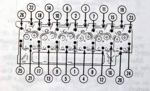
I went in 25ft/lb increments from loose to 125ft/lbs in the typical spiral pattern. The initial 25ft/lb, 50ft/lb, and 75ft/lb increments were repeated as needed till all were at the full value before proceeding to the next increment.
With that, go about reassembling the balance of the engine, adjusting the valves, etc. leaving the valve covers off.
Bring the engine to full operating temperature as it sits in the driveway and re-torque the stud nuts with the engine hot, using the sequence shown above.
Readjust the valves ~ Intake: 0.008". Exhaust: 0.018" (engine hot).
Now button it up.
When re-torquing, many advocate reapplying the assembly lube. Some don't. Check with your product's manufacturer. Regardless, when re-torquing, back off the individual nuts 1/4th turn and using a single, uniform pulling motion, bring it back to it's final torque figure.
The reason for backing off a little is that sometimes, the torque required to get things moving, is more than the final torque value.
NOTE: With a standard, non O-ringed head, this will suffice. When running O-rings, it is strongly recommended that one gently run the engine with normal LOW boost for a week and torque again. Generally, one wants to re-torque till the nut no longer turns any further than it was to start with meaning; Mark the nut and note it's relation to all around it. Back the nut off 1/4th turn and draw it up. If the mark is moved forward of where it was to start with, plan on re-torquing again after another week of gentle driving. Once things are at the point the nut doesn't turn any further, you should be good to go.
A FINAL NOTE: I finally got a chance to talk with the folks at PDR about the A1 brand studs I bought from them. The instructions that came with the studs I used are in fact developed and printed by the manufacturer, A1. Therefore, the instruction I present above is based on those printed instructions.
The reason I bring this up is that nearly every CTD engine builder has their own way of doing re-torques. Some advocate hot re-torques, some don't. Some advocate cold re-torques, some don't. In the case of the A1 product, pending hot or cold, some recommend the final figure be 125ft/lbs hot, others, 135ft/lbs cold.
BE SURE TO CONTACT YOUR PRODUCTS MANUFACTURER AS TO HOW TO DO YOURS!
I hope this proves helpful in illustrating the common procedures with installing studs in your mess.
Y'all drive safely and save the racing for the track.
Thread Starter
1st Generation Admin
Joined: Jan 2005
Posts: 4,601
Likes: 118
From: Buies Creek, NC
I need to point out that I've edited the last part of my post regarding the final torquing procedure.
Specifically, the hot-torquing method.
As now presented above, the final torquing instruction is based solely on the printed instruction provided with my studs as purchased from PDR. I'm gonna call them and verify if this is still their current thinking.
Like many things, the torquing procedure is all over the map when asking on-line it seems. Many professionals advocate hot-torquing, many equally qualified don't. The same goes for the final torque figure.
I don't make the things, so I'm left with that designated by those who do.
I strongly advise one reads, understands, and follows those instruction provided with your product. If you're not sure, call the manufacturer.
Trending Topics

Registered User
Joined: Nov 2007
Posts: 335
Likes: 0
bahahahahahahaha, sorry, im listening
Great wright up it will help alot!
 . Luckly only 1 got hert.
Registered User
Joined: Jul 2007
Posts: 358
Likes: 0
From: Yacolt, WA
[QUOTE=I know two people in my life that have try to suck gas out of a car with a shop vacuum, and thought nothing of it. Luckily only 1 got hurt.[/QUOTE]
My kid brother used a shop vac to suck some gas out of the hull of his jet ski. . .
The shop vac didn't make it. He lived to do many more intelligent things. . .
. Luckily only 1 got hurt.[/QUOTE]My kid brother used a shop vac to suck some gas out of the hull of his jet ski. . .
The shop vac didn't make it. He lived to do many more intelligent things. . .

Thread
Thread Starter
Forum
Replies
Last Post
lostcreek21
12 Valve Engine and Drivetrain
7
Mar 1, 2010 06:13 PM
hic316
Performance and Accessories 2nd gen only
38
Jan 12, 2008 10:03 PM
74dart
Performance and Accessories 2nd gen only
5
Jul 7, 2007 07:58 PM

