AC Cycling switch.

 08-11-2006, 07:04 PM
#17
Registered User
Join Date: May 2003
Location: Edmonton Alberta, Canada
Posts: 332
Likes: 0
Received 0 Likes
on
0 Posts
Jim....... (by the way, congratulations on your nifty web-name) Thanks for the information and pictures. I have one comment. While my collection of Bosch relays does include a number of the one's you have used, none of them were labeled as for use on a Gen 1. Mine came from some old junked volvo's. These are from other people's volvo's as none of mine ever died by my hands. {They were like the CTD.. useful enough and worth enough to bother maintaining and keeping.} I have a bunch more of other Bosch relays and will now give them a much higher status in my junk collection. My OEM A\C switch has not crapped out- YET but I sure know how to fix it when it does. I don't suppose that it matters that my version of your relay has an aluminum case with a schematic stamped into the side.
Thanks again........ oh, yeah, thanks for telling me what the other stuff inside of a Bosch relay is for. I always wondered but never bothered to look into it.
Thanks again........ oh, yeah, thanks for telling me what the other stuff inside of a Bosch relay is for. I always wondered but never bothered to look into it.
08-11-2006, 07:08 PM
#18
Registered User
Join Date: May 2003
Location: Edmonton Alberta, Canada
Posts: 332
Likes: 0
Received 0 Likes
on
0 Posts
Just for the heck of it and not meaning to hijack this thread, I found out that those dry erase markers are perfect for highlighting stampings so that they can be read easily. Rub the marker all over the stamping and wipe off what you can. What remains is wonderfully clear. The schematic on the side of my metalic cased relays is bright and clear and reveals that they are EXACTLY as you have described.
08-11-2006, 09:28 PM
#19
Administrator
Thread Starter

Here is what most people don't usually see.
Bosch is on the left and Generic in on the right.
Notice the contacts and the coil bobbin
These are in my photo gallery.
Jim
[IMG]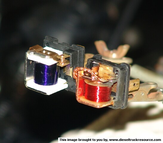 [/IMG]
Bosch is on the left and Generic in on the right.
Notice the contacts and the coil bobbin
These are in my photo gallery.
Jim
[IMG]
[/IMG]
08-13-2006, 06:36 AM
#20
Administrator
Thread Starter
Originally Posted by Lightweight
Hey Guys, this mud just might be gettin' a little bit clearer.
One last question. The probe in the low pressure (suction) side line is a bimetal to ground? Yes? That would make it the switch for 85/86, switching the ground instead of hot side, I hope maybe . This would be with a diode protected relay.
Sorry if I'm slow, it's been a while, poa and expansion valve era.
Thanks again to Jim and everybody else
GW
[EDIT] If I install a 1 amp fuse in the jumper from 30 to 86 on a diode relay(0 332 019 155) then the load won't burn out the relay, correct?
One last question. The probe in the low pressure (suction) side line is a bimetal to ground? Yes? That would make it the switch for 85/86, switching the ground instead of hot side, I hope maybe
. This would be with a diode protected relay.Sorry if I'm slow, it's been a while, poa and expansion valve era.
Thanks again to Jim and everybody else
GW
[EDIT] If I install a 1 amp fuse in the jumper from 30 to 86 on a diode relay(0 332 019 155) then the load won't burn out the relay, correct?
Sorry if I'm slow, it's been a while, poa and expansion valve era.
How about R-12 for $.39 can
Lightweight:
The probe that is inserted into the suction line is actually a thermistor (a type of resistor that the resistance varies with temperature), the black box it is connected to that is mounted on the "H" valve has a driver circuit that drives a small dip relay that then switches the power to the compressor coil.
The BLUE/ white wire is the lead that the cycling switch uses to sense that the AC is calling for cold and is a switched ground.
The thermistor seems to have a cold resistance of 6400 ohms @ 32* and a hot resistance of 1300 ohms @ ambient of 80* I got this using a standard accepted method. (ice bath and a calibrated heat source)
From the circuit board I removed from the potting it looks the thermistor is fed into a 555 IC probably being used as a comparator and the switching temperature is set by a couple of zener diodes being used to set a reference voltage.
The 555 is also being used as the driver to switch the coil of the internal DIP relay.
The relays output then switches line voltage in the conventional manner to the compressor coil.
It is really a simple and stable device but the shortcomings were the contacts on the relay.
Also as far as the relay, it should not burn out any sooner because it does not matter which end of the coil is fed with the power or switched.
Here are a few designs given for Mobile Electronics Installers.
http://www.the12volt.com/relays/page1.asp
The coil is not going to receive the full current of the battery because there is internal resistance in the control wiring back to the switch due to the small gauge and the length of the run.
Out of curiosity I checked the current draw of the coil with my Fluke 87 and it was 105ma. for the control circuit.
Page 10 shows the nominal current of 140 ma.
http://www.lamborghini-talk.com/foru...terminals'
Rammer64 Quote:
your schematic will still put the heavy amp draw and load unnecessarily on the coil within the relay. It is a 40amp relay but it is designed THROUGH the #30-#87/87a circuit. The relay isn't designed to have the 40 amp draw across the coil directly. The relay don't need all that amperage to hold the coil in. It only uses a little amperage to work. It will work, but it will have a strong tendancy to BURN/FUSE the relay contacts together and causing the relay to stick "ON" or burn out the coil in the relay.
I still do not see why there would be a 40-amp draw across the coil?
True, there could be up to a 30 amp load across #30 & #87 or #87a but not the coil because even though the battery positive is connected to either #85 or #86 the coil is completing its path to ground through the controlling circuit in this case it is the switched ground signal from the AC controls.
So it is essentially 2 separate circuits.
There would only be a 40? /30 amp draw across the relay contacts IF the load was actually consuming that much current not because it is a 30 amp relay.
This is only the maximum rated load.
Burning or sticking the contacts of a relay can usually be prevented by suppressing the arc across the contacts from the load the simplest way is to install a sufficient size diode in parallel across the load if it is inductive or a capacitor from relay to ground.
Inductive loads like in blowers or coils, solenoids are the worst because of the back EMF they create when the magnetic field collapses. This is the principle behind how a Kettering ignition is designed to operate.
Notice when you apply power to an Ignition coil the spark comes after the points are open
Burned contacts are also caused by under sizing the rating of the relay.
I have had some relays actually melt from overheating the contacts but I would replace the relay with a Bosch relay it would operate as I had expected it to.
The composition of the actual contacts make a big difference also, cheap relays are usually just copper where as better ones are made of Hard Silver or Silver Nickel, Tungsten.
When the contacts arc bits of the pads are melting and depositing to the opposite contact.
(remember filing your points in your distributor how it always looked like a little mountain?)
As you can see in a few post back what the relays actually look like on the inside.
The generic one I got from Target, they were selling them for $.50 each they were sold under BLAZER name for fog lights. I couldn�t pass them up but I have had to replace every one of them due to a failure of one kind of another.
Motors have a heavy startup surge that tapers off drastically after it comes up to speed so if you install them on a blower or air compressor because it might only draw 10 amps, it is probably pulling 40-50 amps at startup. And if it is an air compressor it might work fine when you tested it, but when you have a full head of air you could be at the high end again.
I had a Bosch electric fan off a Mercedes on my Chevy LUV that I had a small block Chevy and it would draw 80 amps on startup for about 5 seconds till it came up to speed then drop to 5 amps.
Your question about the fuse, it would not hurt to protect the coil,
It would make more sense when using a grounded coil with a (+) switched trigger but only to protect the actual control circuit from a short circuit like if the wire got pinched or the coil went to ground, and you would have the fuse at the other end of the circuit.
I see how you are trying to protect the coil but I don�t think it would help much. If the ground state trigger got shorted out, most it would do is stay on till you pulled the wire.
That is why this configuration is safer. {Same way your horn circuit is wired}
Now if the contacts ever got so hot that the coil bobbin melted and shorted out internally I would see the need but the fuse already in place would protect the rest of the electrical system.
A resistor or a diode in series with the coil lead could be used to limit the current if you wanted.
As I am thinking, I have at least 8 relays controlling something in my truck.
When I worked for the Los Angeles County as a Diesel Mechanic I had to take a mechanics class to be certified and every time I would ask a question the teacher could not answer so they had me teach the class. He would keep saying "Lane sit down"
There were electrical problems that they could not diagnose and fix. The senior mechanics and electricians worked on them you weeks
so they put them in the bone yard, I checked them and had the problems diagnosed and repaired within 20 minuets, even pinched wiring harness in the bulkhead that could not be seen by the eye.
Here some links with some good circuits for us techno-minded people.
http://www.the12volt.com/relays/relays.asp
This is a BOSCH catalog should be downloaded for reference.
http://www.lamborghini-talk.com/foru...ys%20terminals
Sorry for the long post my mind was just in motion again.
Jim
08-13-2006, 06:58 AM
#21
Administrator
Thread Starter
Originally Posted by Lightweight
OK Jim.
Guess i'll chase my tail for a little while .
I was under the impression that this mod would lower the vent temps by keeping the comperssor running longer but not to freese up, well most of the time.
My system is runnin' fine except for the vent temps which are 50 dgr. at best .
If this don't improve things then I'll do the $31 heater bypass valve from NAPA.
I'll still have the parts in my truck for when the switch does fail, hummmm, got two switches already, guess three will work too.
I'm giong to try this this weekend and will post again. It's cheaper than the bypass valve.
GW
Guess i'll chase my tail for a little while
.I was under the impression that this mod would lower the vent temps by keeping the comperssor running longer but not to freese up, well most of the time.
My system is runnin' fine except for the vent temps which are 50 dgr. at best
.If this don't improve things then I'll do the $31 heater bypass valve from NAPA.
I'll still have the parts in my truck for when the switch does fail, hummmm, got two switches already, guess three will work too.
I'm giong to try this this weekend and will post again. It's cheaper than the bypass valve.
GW
*The sight glass is clear correct?
*Is the AC colder when you first start the engine V/S 20 minuets of running time?
* Is the air colder around town or when you are going 50 MPH?
* Do you have a good vacuum? do all of the servos operate on the air box? When AC is on does the vent close for recirculate, it is the one you can see below the dash and glove box, through the vent grille.
*Do you have a lot of condensate dripping from your truck?
* Is your water valve closing? should move when slider is moved to COLD side.
You said something pulling the probe out till it iced up?
this leads me to belive the AC is working but it is being reheated
There are alot of vacuum devices that have to be in the right place for this to work properly.
Inside the air box there are several blend doors that move and direct the air through the heater core.
Tell me what you have done.
Jim
08-13-2006, 10:10 AM
#22
Registered User

Join Date: Feb 2006
Location: Hartsville SC
Posts: 74
Likes: 0
Received 0 Likes
on
0 Posts
Hi Jim,
Darnit, thought I was about done .
Freon for $6.00 a case in any parts store, stacked up like oil, ahhh, the good old days.
What all have you done to the truck" maybe I can point you were to look.
*The sight glass is clear correct? (YES)
*Is the AC colder when you first start the engine V/S 20 minuets of running time? (NO, the thermometer reads incab temp, say 105 drg., then SLOWLY drops to 50-51. Takes maybe 5 to 7 min. for the duct temp to come down that far.)
* Is the air colder around town or when you are going 50 MPH? (NO, it makes no difference. Although at idel, after runnin' for 30-45 min. it will pull down to about 49 drg.(sometimes but is not consistenant) Bought the thermometer with the big dial .)
.)
* Do you have a good vacuum? do all of the servos operate on the air box? When AC is on does the vent close for recirculate, it is the one you can see below the dash and glove box, through the vent grille. (Have not put a gauge on to see but the brake booster works as it should. I'll check the servos this afternoon. When I change from AC to MAX on the control buttons there is a drop in temp. so I'm thinking that servo is workin' but will check it out.
*Do you have a lot of condensate dripping from your truck? (Depends on the humidity, but doesn't seem to be more than the wife's Lincoln.)
* Is your water valve closing? should move when slider is moved to COLD side. (I didn't check it that way but will when the wife gets back. Just pulled the vacuum hose off. Yes it opened and closed. Might be leaking by though.)
You said something pulling the probe out till it iced up? (Yes, a 1/2" at a time till it froze up. Even tried duct tapin' the probe to the outside of the low pressure line, froze up there too
  .)
.)
this leads me to belive the AC is working but it is being reheated
There are alot of vacuum devices that have to be in the right place for this to work properly.
Inside the air box there are several blend doors that move and direct the air through the heater core. (Guess if all else fails I'll install the bypass valve in the heater lines .)
Tell me what you have done.
Jim
Darnit, thought I was about done
.Freon for $6.00 a case in any parts store, stacked up like oil, ahhh, the good old days.
What all have you done to the truck" maybe I can point you were to look.
*The sight glass is clear correct? (YES)
*Is the AC colder when you first start the engine V/S 20 minuets of running time? (NO, the thermometer reads incab temp, say 105 drg., then SLOWLY drops to 50-51. Takes maybe 5 to 7 min. for the duct temp to come down that far.)
* Is the air colder around town or when you are going 50 MPH? (NO, it makes no difference. Although at idel, after runnin' for 30-45 min. it will pull down to about 49 drg.(sometimes but is not consistenant) Bought the thermometer with the big dial
.)* Do you have a good vacuum? do all of the servos operate on the air box? When AC is on does the vent close for recirculate, it is the one you can see below the dash and glove box, through the vent grille. (Have not put a gauge on to see but the brake booster works as it should. I'll check the servos this afternoon. When I change from AC to MAX on the control buttons there is a drop in temp. so I'm thinking that servo is workin' but will check it out.
*Do you have a lot of condensate dripping from your truck? (Depends on the humidity, but doesn't seem to be more than the wife's Lincoln.)
* Is your water valve closing? should move when slider is moved to COLD side. (I didn't check it that way but will when the wife gets back. Just pulled the vacuum hose off. Yes it opened and closed. Might be leaking by though.)
You said something pulling the probe out till it iced up? (Yes, a 1/2" at a time till it froze up. Even tried duct tapin'
the probe to the outside of the low pressure line, froze up there too .)this leads me to belive the AC is working but it is being reheated
There are alot of vacuum devices that have to be in the right place for this to work properly.
Inside the air box there are several blend doors that move and direct the air through the heater core. (Guess if all else fails I'll install the bypass valve in the heater lines
.)Tell me what you have done.
Jim
08-13-2006, 04:49 PM
#23
Registered User
Join Date: Feb 2006
Location: Hartsville SC
Posts: 74
Likes: 0
Received 0 Likes
on
0 Posts
Jim,
I checked everything that you had listed in your post. Even took the glove box out for more room. They were all working as they should, servos, doors, and cables. Bypass valve cycles with the lever.
Sitting under a tree in 85 drg, temp the AC pulled down to 48 at idle. Brought it up to 1200/1300 RPM and the temp went to 50/51. I thought that head perssure and temps went up at idle.
Could the bypass valve be leaking at off idle speeds(guessing here)?
Thanks
GW
08-13-2006, 06:45 PM
#24
Registered User

I sure hope you find the problem. Mine does the same thing. It seems to get comfortable (not cold) at idle but when I drive down the road it seems to cool only slightly more than the outside temp. I am at a loss. The pressures seem to be correct and the compressor isn't cycling excessivly. I did the same thing last month by removing the glove box and checking the door. I finally decided it was the 134 that didn't work well in our trucks but other people here seem to have good luck with it. I'm like you and wonder if hot water is getting by the valve even though it appears to be working. Mine also seems to blow through the vents less at cruise than at idle but that may be my imagination. I can't see it being a vacuum problem if it works at idle.
 08-14-2006, 10:36 AM
#26
Registered User
Join Date: Feb 2006
Location: Hartsville SC
Posts: 74
Likes: 0
Received 0 Likes
on
0 Posts
Shut off valve is next to the firewall on right side of engine compartment in the heater hose. If it is bad, leakin' by, it can be replaced with a bypass valve from NAPA, about $31. Where is that darn part #. I will find it and post later .
GW
GW
08-14-2006, 03:34 PM
#28
Adminstrator-ess
Originally Posted by Blowndodge
where is the water valve? I though Dave said its never closed, just that the vent covers the heater coil?
06-18-2007, 05:12 AM
#29
Administrator
Thread Starter
Correction
Here are the instructions on how you car replace the electronic cycling switch that is used to control the AC clutch on your first generation Dodge trucks with a standard BOSCH or any ISO relay.
The cycling switch has a probe that is inserted into the suction line at the "H" valve and is used to throttle the compressor to prevent the evaporator from freezing.
When the small dip relay that is potted deep inside this module goes bad, your AC may either become erratic and stop working when you hit a bump and start working again when you perform the secret Mopar closed fisted rap on the dashboard.
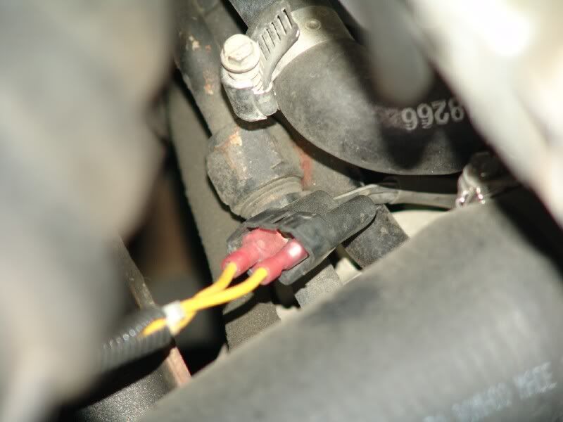
Here is where the connector is where the old inoperative cycling switch used to be connected to, I cut all 3 wires loose and you see we are only going to use the BLUE wire with the WHITE tracer. The BLUE and BROWN wire will not be used.
You should see the wires on yours more clearly; I have additional cables going to my linear accelerator.
FYI The BLUE/WHITE tracer wire has a switched ground signal.
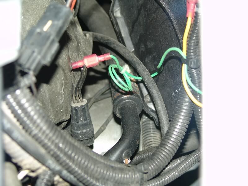
This is what will now be controlling the clutch of the compressor.
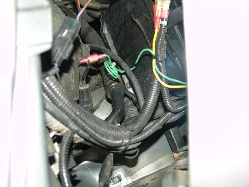
This is how I mounted mine but I was in a hurry when I designed this and I was in the middle of a Home Depot parking lot while on a road trip.
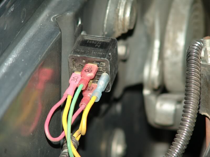
This is a better view of the install. See how I installed a small fuse inline using 2 female spade connectors? This works quite well for any application. I took the 12 VDC from my #2 auxiliary battery. I know I see the dirty battery..
The 1/2 X 9/19 wrench is the emergency battery wrench and is stuck to the fender panel by 2 rare earth magnets and is very hard to remove.
Here is the connection to the compressor clutch coil. I have the original harness tucked away so I can always revert back if needed or I come up with something new.
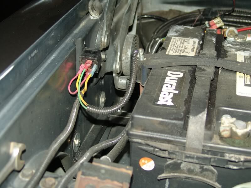
Here is a little wider shot behind my #2 battery showing the connector and the fuse.
You see at the end of the suction line there is a socket where the probe is inserted to monitor the temp.
BTW none of the wiring has been modified to the low-pressure cutout switch that is mounted to the "H" valve.
Very important... I have heard some say this Low Pressure cutout switch can be replaced and a new one installed, JUST UNSCREW IT...
NO NO NO there is no Schrader valve behind this and you will release all of your refergent before you could find the switch to put it back in.
I know GM's you can replace easily and maybe some of ours but I know for certain mine was NOT tapped for a Schrader.
Here is a simple line drawing of the entire setup,
Sorry I did not get around to draw it on my computer.
About the only change I would make to this design would be to install a diode across the relay coil to clamp the spike induced by the collapsing field.
Bosch also has a relay with one installed internally.
If you use one of these you have to pay particular attention to the polarity or it will be a dead short.
As I mentioned before, the downside to this setup is sometimes if the blower is on low speed, the evaporator can ice up and you will have to manually throttle the compressor to off until it thaws out.
Another downside is this makes my truck SOO uncomfortably cold inside I actually have to wear a jacket and everyone yells turn off the air, I�m cold.
NOTE. The "To Battery" goes to the Positive terminal
This should cost you around $6.00 if you are buying a genuine Bosch relay and maybe take about 1 hour.
I rate this as SIMPLE.
Let me know if you have any questions I can answer for you.
Jim in Southern California.
The cycling switch has a probe that is inserted into the suction line at the "H" valve and is used to throttle the compressor to prevent the evaporator from freezing.
When the small dip relay that is potted deep inside this module goes bad, your AC may either become erratic and stop working when you hit a bump and start working again when you perform the secret Mopar closed fisted rap on the dashboard.
Here is where the connector is where the old inoperative cycling switch used to be connected to, I cut all 3 wires loose and you see we are only going to use the BLUE wire with the WHITE tracer. The BLUE and BROWN wire will not be used.
You should see the wires on yours more clearly; I have additional cables going to my linear accelerator.
FYI The BLUE/WHITE tracer wire has a switched ground signal.
This is what will now be controlling the clutch of the compressor.
This is how I mounted mine but I was in a hurry when I designed this and I was in the middle of a Home Depot parking lot while on a road trip.
This is a better view of the install. See how I installed a small fuse inline using 2 female spade connectors? This works quite well for any application. I took the 12 VDC from my #2 auxiliary battery. I know I see the dirty battery..
The 1/2 X 9/19 wrench is the emergency battery wrench and is stuck to the fender panel by 2 rare earth magnets and is very hard to remove.
Here is the connection to the compressor clutch coil. I have the original harness tucked away so I can always revert back if needed or I come up with something new.
Here is a little wider shot behind my #2 battery showing the connector and the fuse.
You see at the end of the suction line there is a socket where the probe is inserted to monitor the temp.
BTW none of the wiring has been modified to the low-pressure cutout switch that is mounted to the "H" valve.
Very important... I have heard some say this Low Pressure cutout switch can be replaced and a new one installed, JUST UNSCREW IT...
NO NO NO there is no Schrader valve behind this and you will release all of your refergent before you could find the switch to put it back in.
I know GM's you can replace easily and maybe some of ours but I know for certain mine was NOT tapped for a Schrader.
Here is a simple line drawing of the entire setup,
Sorry I did not get around to draw it on my computer.
About the only change I would make to this design would be to install a diode across the relay coil to clamp the spike induced by the collapsing field.
Bosch also has a relay with one installed internally.
If you use one of these you have to pay particular attention to the polarity or it will be a dead short.
As I mentioned before, the downside to this setup is sometimes if the blower is on low speed, the evaporator can ice up and you will have to manually throttle the compressor to off until it thaws out.
Another downside is this makes my truck SOO uncomfortably cold inside I actually have to wear a jacket and everyone yells turn off the air, I�m cold.
NOTE. The "To Battery" goes to the Positive terminal
This should cost you around $6.00 if you are buying a genuine Bosch relay and maybe take about 1 hour.
I rate this as SIMPLE.
Let me know if you have any questions I can answer for you.
Jim in Southern California.
On the line drawing at the end of the article shows the relay terminals #30 and #85 being connected through a 20-amp fuse to the BATTERY,
** This is a corrected drawing showing Term. #30 is connected to the battery (+) and Term. #86 is connected the any fuse terminal that is switched by the IGNITION other than the RADIO,RWAL or ECM fuse, Term. #85 is connected to the switched ground signal from the cycling swich.
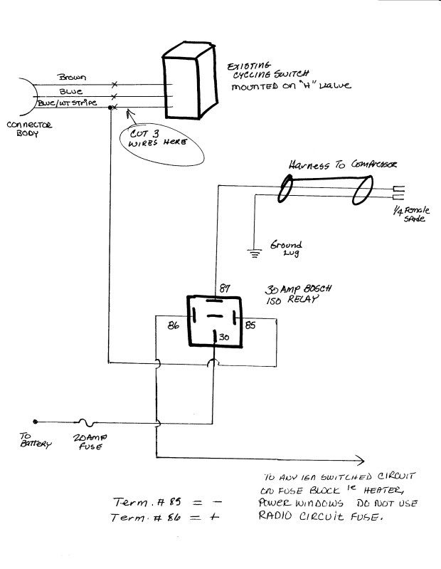
Thank you 97Catintenn for bringing this to my attention.
Jim
06-19-2007, 02:30 PM
#30
Registered User

Join Date: Feb 2007
Posts: 2
Likes: 0
Received 0 Likes
on
0 Posts
I apologize for being back such an old post, I found this while I was searching on where to obtain a clutch cycling switch for my '90 CTD. This looks like my best bet to replace the switch, I just have one question about this set-up, and a very newb question at that... Where can I get a Bosch 30 amp ISO relay? Is this something a parts store will have?
Thanks,
Chris
P.S. Awesome write up, I thank God every day that he gave me enough sense to know when to take advice from people with more wisdom than me!
Also since this is my first post...this is my truck.

Thanks,
Chris
P.S. Awesome write up, I thank God every day that he gave me enough sense to know when to take advice from people with more wisdom than me!
Also since this is my first post...this is my truck.