Power steering leak
 02-14-2012, 07:32 PM
#1
Registered User
Thread Starter

Join Date: Jan 2011
Location: Pahokee, Fl
Posts: 54
Likes: 0
Received 0 Likes
on
0 Posts
Power Steering leaking
My power steering gear box is leaking from
the adjustment screw. I've tried tightening the lock nut but it still leaks. The leak has slowed, but not stopped. I don't know what to do .
.
Also, for some reason, the transmission seems to get stuck (not able to accelerate) when in fourth or fifth gear while driving at slower speeds. Example, fifth gear, 50 mph, if I drive at that speed for a few min. I have to switch in and out of gear to get it to accelerate. I know, I've got a lot of problems.
Any help would be GREATLY appreciated.
the adjustment screw. I've tried tightening the lock nut but it still leaks. The leak has slowed, but not stopped. I don't know what to do
.Also, for some reason, the transmission seems to get stuck (not able to accelerate) when in fourth or fifth gear while driving at slower speeds. Example, fifth gear, 50 mph, if I drive at that speed for a few min. I have to switch in and out of gear to get it to accelerate. I know, I've got a lot of problems.
Any help would be GREATLY appreciated.
Last edited by BIG SHANE; 02-14-2012 at 08:18 PM. Reason: i have to pull my camper 800 miles for new job in two weeks
 02-15-2012, 12:10 PM
#3

That's not a leak, that's the Constant Fluid Change feature. I have CFC on many of the systems in my truck!
Actually, I'm not really sure about the power steering leak--I've never seen a box leak out of the adjustment screw on either of my trucks. Maybe some seal has failed?
The fifth gear issue sounds really interesting--are you saying after a certain amount of time at a steady speed you find that the truck won't accelerate? And that happens in both 4th and 5th?
02-15-2012, 12:31 PM
#4
Registered User
Thread Starter
Join Date: Jan 2011
Location: Pahokee, Fl
Posts: 54
Likes: 0
Received 0 Likes
on
0 Posts
Midnite,
Thanks for the reply. I like the cfc reference. That was a good one.
The leak I've cleaned the area and watched it while my son turns the wheel and it definatly is coming out at the adjustment screw. I've been looking all over the internet to find a exploded view to see if somthing is missing or if there is a o-ring that could be replaced. But I can't find one. I hate to have to buy a new box if its somthing simple.
As far as the transmission issue goes, yes, its really crazy I'll be driving along at 45 or so and try to accelerate and nothing. If I shift gears back and forth a couple times magically it will accelerate. This problem is only at slower speeds. At 60 and up no problem. I'm wondering if there is some sort of sensor that's going bad.
I probably should have these posted seperatly.
02-15-2012, 02:57 PM
#5
Registered User
Thread Starter
Join Date: Jan 2011
Location: Pahokee, Fl
Posts: 54
Likes: 0
Received 0 Likes
on
0 Posts
This afternoon I checked my fluid levels then drove my truck for about fifteen min. The PS pump started whining. The res. Was almost empty. Refilled it drove home and parked it. Cleaned up the mess
I don't know how to fix it. Guess I'm gonna have to take it out. I wish someone had some idea what could cause it to leak at the adj screw before I spend a lot of money
I don't know how to fix it. Guess I'm gonna have to take it out. I wish someone had some idea what could cause it to leak at the adj screw before I spend a lot of money
02-15-2012, 04:51 PM
#6
Administrator

This afternoon I checked my fluid levels then drove my truck for about fifteen min. The PS pump started whining. The res. Was almost empty. Refilled it drove home and parked it. Cleaned up the mess
I don't know how to fix it. Guess I'm gonna have to take it out. I wish someone had some idea what could cause it to leak at the adj screw before I spend a lot of money
I don't know how to fix it. Guess I'm gonna have to take it out. I wish someone had some idea what could cause it to leak at the adj screw before I spend a lot of money
STEERING / STEERING GEAR & LINKAGE / STEERING GEAR & LINKAGE / OVERHAUL KIT
3893558 - OVERHAUL KIT All Models; Side Cover Seal POWER
MSRP Core Online Price
$27.35 $0.00 $19.35
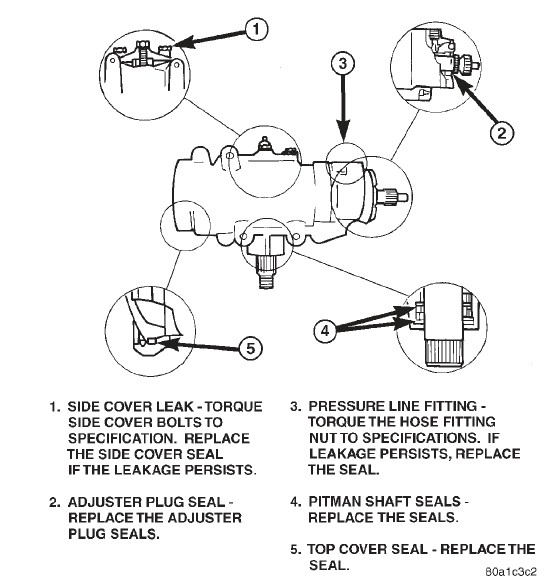
Here is the illustration.
 02-15-2012, 04:54 PM
#7
Registered User

I'm sure it is something like a silly o-ring or seal, but I don't know for sure. My steering box started weeping from a little hole at the top-front of the box, and I ended up just replacing the box. Easier, more money, but in the end I had a new steering box. I'll see if I can dig up the diagrams and rebuild kits I found, because I was going to do the same thing at first.
Trending Topics
02-15-2012, 05:24 PM
#8
Registered User
Thread Starter
Join Date: Jan 2011
Location: Pahokee, Fl
Posts: 54
Likes: 0
Received 0 Likes
on
0 Posts
Patdaly, I'm not sure if the cover gasket would stop the leak from the adjustment screw or not, but will look into that. I have not taken the cover off yet.
Gorms, I haven't noticed a weep hole anywhere. But I am very sure its coming out off the adjustment screw. I cleaned the whole area with brake cleaner and watched it build up under the lock nut before pouring out on the ground. If you find the diagrams please send them. Even if I don't rebuild it , they would be good to have.
Bigshane4413@gmail.com
 02-16-2012, 07:12 PM
#10
Cummins Guru
Most likely the cover has cracked on steering gear box. Drop the gear box and check really good for a crack around the adjuster screw
Trans problem most likely 5th gear nut came loose
Read TSB it applies to your problem.
SUBJECT: Loss Of Fifth Gear
DATE: Sep. 25, 1998
THIS BULLETIN SUPERSEDES TECHNICAL SERVICE BULLETIN 21-10-98, WITH AN EFFECTIVE DATE OF SEP. 11, 1998, WHICH SHOULD BE REMOVED FROM YOUR FILES. ALL REVISIONS ARE HIGHLIGHTED WITH **ASTERISKS** AND INCUDES ADDING THE 1999 MODEL YEAR AND A NEW PROCEDURE TO INSTALL THE FIFTH GEAR NUT.
NOTE: THIS BULLETIN APPLIES TO VEHICLES EQUIPPED WITH A NV4500 MANUAL TRANSMISSION AND THE 8.0L V10 GAS ENGINE OR THE 5.9L CUMMINS DIESEL ENGINE.
SYMPTOM/CONDITION:
Transmission operates normally through all ranges except fifth gear.
DIAGNOSIS:
Depress the clutch, start the engine, then shift the transmission into fifth gear. Slowly release the clutch to verify that the vehicle can move (or engine rpm drops due to the load applied to the engine) with the transmission engaged into fifth gear. If the vehicle does move (or engine rpm drops due to the load applied to the engine) with the transmission engaged into fifth gear, the vehicle will need to be road tested. If the vehicle does not move (or engine rpm does not drop when the clutch is released) with the transmission engaged into fifth gear, perform the Repair Procedure.
Road test the vehicle on a road that will allow you to operate the vehicle safely in fifth gear. If during the road test, the transmission pops out of fifth gear or fifth gear cannot be obtained, perform the Repair Procedure.
PARTS REQUIRED:
Qty Part No. Description
1 04741551 Gear, Fifth
1 05013887AA Nut, Clamp, Package
1,Clamp Nut Assembly
1,Spring Disc Washer
1,Loctite #272 (Mopar p/n 05014205AA)
1 04897150AA Cleaner, Mopar Brake Parts
4 04874459 Lubricant, Mopar Manual Transmission
1 04318031 Adhesive, Mopar Lock & Seal
1 04318083 Maker, Mopar Gasket
REPAIR PROCEDURE:
This bulletin involves installing a new fifth gear, spring disc washer, and a revised fifth gear clamp nut.
Shift the transmission into neutral.
Raise the vehicle on an appropriate hoist.
If equipped, remove the skid plate.
Place a drain pan under the transmission.
Remove the PTO cover bottom bolt and drain the lubricant out of the transmission (Figure 1).
Using a suitable marker, mark a line across the rear axle pinion yoke and the rear propeller shaft yoke for installation reference.
If equipped with a two-piece propeller shaft, with a suitable marker, mark the outline of the center bearing on the frame crossmember for installation reference. Then, remove the bolts that attach the center bearing to the support bracket (Figure 2).
Remove the bolts holding the universal joint clamp to the pinion yoke.
Slide the slip yoke off the transmission/transfer case output shaft and remove the rear propeller shaft. If the vehicle is a 4X4, proceed to Step 10. If the vehicle is a 4X2, proceed to Step 21.
With a suitable marker, mark a line across the front propeller shaft yoke at the transfer case and the propeller shaft yoke at the rear of the front propeller shaft.
Mark a line across the propeller shaft yoke at the front of the front propeller shaft and the front pinion shaft yoke.
Remove the universal strap bolts at the front pinion shaft yoke (Figure 3).
Remove the bolts holding the propeller shaft to the transfer case yoke flange.
Remove the front propeller shaft.
Disconnect vent hose and vacuum harness at transfer case switch.
Disconnect transfer case shift linkage at transfer case range lever. Then, remove transfer case shift mechanism from transmission.
Support transfer case with transmission jack. Secure the transfer case to the jack with safety chains.
Remove transfer case attaching nuts.
Move transfer case rearward until transfer case input shaft clears transmission output shaft.
Lower transfer case assembly and move it from underneath vehicle.
Support the transmission with a jack.
Remove bolts attaching transmission mount to the rear crossmember.
Remove bolts attaching exhaust pipe hanger to the transmission.
Remove the eight bolts that attach the extension/adapter housing to the gear case (Figure 4).
Remove extension/adapter housing.
NOTE: THERE IS ONE ALIGNMENT DOWEL IN THE GEAR CASE AND ONE IN THE EXTENSION/ADAPTER HOUSING.
If equipped, remove rubber spline seal from end of mainshaft (Figure 5) and discard. The seal is mainly used to prevent lubricant loss during shipping and does not have to be replaced.
Install nut wrench special tool 6743 onto fifth gear nut (Figure 6). Be sure wrench is fully engaged in nut slots and is not cocked.
NOTE: THE NUT WRENCH WILL ONLY FIT ONE WAY ON THE NUT.
Position the small end of the nut wrench at approximately the 10 o�clock position (Figure 6).
Install splined socket Special Tool 6993 (4X2) or 6984 (4X4) onto the mainshaft. Then, install a breaker bar onto the splined socket. Wedge the breaker bar so that the mainshaft cannot turn while loosening the fifth gear nut (Figure 7).
Strike the small end of the nut wrench with a heavy soft face hammer to break the nut loose. During assembly, the nut has been tightened to 300 ft. lbs. of torque. In addition, it is secured by a an interference fit thread plus Loctite adhesive and will require several firm blows to loosen it. Once the nut is loose, it can be removed by holding the nut wrench with a breaker bar and rotating the output shaft with the spline socket and the breaker bar (Figure 7).
NOTE: THE NUT MAY ALREADY BE LOOSE AND WILL NOT REQUIRE YOU TO STRIKE THE NUT WRENCH TO LOOSEN THE NUT.
Remove the roll pins that secure the countershaft fifth gear shift fork to the shift rail with a pin punch (Figure 8). Drive the roll pins from the bottom of the fork and not the top.
Remove the snap ring that secures the fifth gear clutch hub and gear onto the countershaft (Figure 9).
Remove fifth gear shift fork, gear and hub, and synchronizer components as an assembly. Remove assembly by tapping shift fork off rail with a plastic mallet.
Remove countershaft fifth gear needle bearing assembly and the cone shaped rear bearing thrust washer from the end of the countershaft. Note the position of the washer for assembly reference. Also note that the washer bore has a notch for a retaining pin.
Remove and retain thrust washer locating pin from countershaft.
Remove fifth gear from the mainshaft using puller Special Tool Set 6444 and the following procedures.
Position first half of puller jaw Special Tool 6820 onto the fifth gear (Figure 10).
Assemble puller flange Special Tool 6444-1 and puller rods Special Tool 6444-3 for 4X2 models or 6444-4 for 4X4 models (Figure 11).
Slide assembled puller flange and rods onto output shaft. Then, seat flange in notch of puller jaw.
Position second puller jaw Special Tool 6820 onto gear and the notch on the puller flange.
Slide retaining collar Special Tools 6444-8 over puller jaws to hold them in place (Figure 12).
Install puller and bolt (Special Tool 6444) onto puller rods. Then, secure the puller to rods with the retaining nuts (Figure 13).
Tighten puller bolt to remove gear from shaft splines.
Clean the mainshaft threads with a wire brush.
Clean the mating surface of the extension/adapter housing and the gear case with Mopar Brake Parts Cleaner p/n 04897150AA.
CAUTION: THE REAR SEAL OF THE EXTENSION/ADAPTER HOUSING MUST BE PROTECTED FROM THE MOPAR BRAKE PARTS CLEANER WHEN CLEANING THE HOUSING�S MATING SURFACES.
Install new fifth gear p/n 04741551 onto the mainshaft. Use installer Special Tool 6446 to seat gear onto the mainshaft (Figure 14). Gear is seated when it contacts the rear bearing.
Clean threads of the new fifth gear nut (from package p/n 05013887AA) and the mainshaft with Mopar Brake Parts Cleaner p/n 04897150AA.
Install the new spring disc washer (from package p/n 05013887AA) onto the mainshaft. The concave side of the washer must be positioned toward fifth gear (Figure 15).
Apply the Loctite #272 (Mopar p/n 05014205AA) (from package p/n 05013887AA) to the threads of the nut.
**Carefully slide the new nut (from fifth gear nut package p/n 05013887AA) over the mainshaft splines up to the threaded portion of the mainshaft but do not engage the threads at this time. The flat side of the nut must face towards fifth gear and the concave washer (Figure 16).
NOTE: IF THE NUT DOES NOT SLIDE EASILY OVER THE MAINSHAFT SPLINES, LOOSEN THE CROSS BOLT IN 1/4 TURN INCREMENTS UNTIL THE NUT SLIDE OVER THE SPLINES.
Tighten the cross bolt until the gap in the fifth gear clamp nut assembly is closed.
Back the cross bolt out one full turn.
CAUTION: THE ABOVE STEPS ARE CRITICAL FOR THE FIFTH GEAR CLAMP NUT TO FUNCTION PROPERLY.
Install nut wrench Special Tool 6743 onto the fifth gear nut.
Install splined socket Special Tool 6993 (4X2) or 6984 (4X4) onto the output shaft and attach a breaker bar to the splined socket. While holding the fifth gear nut with the nut wrench, tighten the fifth gear nut until the nut bottoms onto the fifth gear spring disc washer. Then, install a high capacity torque wrench onto the fifth gear nut wrench and torque the nut to 366 - 380 N�m (270 - 280 ft. lbs.).
Tighten the cross bolt on the fifth gear nut. Torque the bolt to 11 - 14 N�m (8 - 10 ft. lbs.).**
Install the fifth gear synchronizer thrust washer pin into the countershaft bore (Figure 17).
Install the fifth gear synchronizer thrust washer onto the countershaft. The flat side of the washer faces the rear of the transmission and the tapered side faces the front of the transmission (Figure 17). Turn the washer until the pin engages into the thrust washer notch.
Lubricate the fifth gear needle bearing with gear Mopar NV 4500 Transmission Lubricant p/n 04874459 and install the bearing onto the countershaft.
Install fifth gear shift fork, gear and hub, and synchronizer components as an assembly onto the countershaft and the shift rail.
Install clutch gear snap ring (Figure 9).
Align roll pin holes in shift fork with notches in the shift lug rail. Then, install roll pins from top side of the fork.
NOTE: ROLL PINS ARE DIRECTIONAL AND WILL ONLY FIT PROPERLY ONE WAY DUE TO A SMALLER SHOULDER AT ONE END OF THE PIN.
Verify that the alignment dowels in gear case and extension/adapter housing are in their proper position and are fully seated.
Apply Mopar Gasket Maker p/n 04318083 to the gear case and extension/adapter housing mating surfaces.
Align and install the extension/adapter housing onto the gear case.
Apply Mopar Lock N� Seal p/n 04318031 to the threads of the extension/adapter housing bolts.
Install and tighten the housing bolts to 54 N�m (40 ft. lbs).
Continue reassembly procedures using Step 1 through Step 23 in reverse order.
Once the transmission has been fully assembled, fill the transmission with 3.78 liters (8 pints) Mopar NV 4500 Transmission Lubricant p/n 04874459
02-16-2012, 07:15 PM
#11
Registered User
Thread Starter
Join Date: Jan 2011
Location: Pahokee, Fl
Posts: 54
Likes: 0
Received 0 Likes
on
0 Posts
Wow, that's a lot of parts it doesn't look like there is a oring on the adj screw. Can you send the diagram and parts list to my email?
Bigshane4413@gmail.com
Bigshane4413@gmail.com
02-16-2012, 07:37 PM
#13
Registered User
Thread Starter
Join Date: Jan 2011
Location: Pahokee, Fl
Posts: 54
Likes: 0
Received 0 Likes
on
0 Posts
Bigiron70
Thankyou, for the information about the transmission. Fourth and fifth gear seem to get stuck. Like there is no acceleration. It's really strange. If I accelerate all the way through the gears,like getting on the highway , it operates perfect. It only acts up when going slow for a period of time.
Thankyou, for the information about the transmission. Fourth and fifth gear seem to get stuck. Like there is no acceleration. It's really strange. If I accelerate all the way through the gears,like getting on the highway , it operates perfect. It only acts up when going slow for a period of time.
02-16-2012, 07:42 PM
#14
Cummins Guru
If just fifth gear most likely nut came loose if other gears maybe clutch is slipping or your slave cylinder is binding up and not releasing all the way. Can you smell burning clutch when this happens?
02-16-2012, 07:52 PM
#15
Registered User
Thread Starter
Join Date: Jan 2011
Location: Pahokee, Fl
Posts: 54
Likes: 0
Received 0 Likes
on
0 Posts
No I don't smell the clutch burning. The only way I can explain it is-
I'm driving in town or a road where the speed limit is less than 55. I'm in either fourth or fifth gear for a pd of time. When I push the gas there is no response. So I down shift or just take it out of gear and rev the engine. When I put it back in gear it accelerates fine like there's nothing wrong.
I'm driving in town or a road where the speed limit is less than 55. I'm in either fourth or fifth gear for a pd of time. When I push the gas there is no response. So I down shift or just take it out of gear and rev the engine. When I put it back in gear it accelerates fine like there's nothing wrong.