
Fuel pressures and flows - lift pump, etc.

Thread Starter
Registered User
Joined: Nov 2006
Posts: 1,491
Likes: 3
From: Longmont, CO
Fuel pressures and flows - lift pump, etc.
I have an update. From first hand testing and experience.
My goal was to replace the stock LP with a reliable alternative, and I know everybody is happy with Walbros, so I bought a GSL392. I spent the entire day today, playing with my fuel system and this is what I have found.
I built a bench test setup that is shown on the picture using all 3/8" fittings throughout (except the stock barbed connector on the Walbro suction end) and Nylon-11 3/8" tubing:
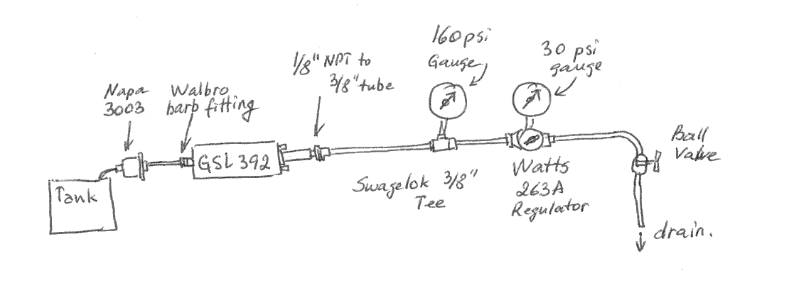
I re-tapped the Walbro output to 1/8" NPT to allow installation of compression fittings. With this setup, the ball valve on the dump line allowed me to create line resistance. The pressure before the valve was stabilized by the Watts regulator. I ran the GSL392 and noted the pressures it developed, while measuring the flow from the dump.
I took only a few measurements of the high pressure gauge because they matched the published Walbro flow curve quite well. At 75 psi I measured 48 GPH and at 55 psi I had ~60 GPH flow. At 20 psi the one gallon jug I used for the dump overfilled before I turned to it and managed to pull off the wires, so I could not take accurate time reading since I was busy cussing and spitting, cleaning up the spill.
If anyone noticed my recent quest to find out what the flow was through the stock engine, you would see the range of suggestions that I got (https://www.dieseltruckresource.com/...d.php?t=137655
You can probably guess where I was going with this: if the flow through is 40-50 GPH, I can run this through my regulator and my GSL392 would run at 80-90 psi, well within the design limit, without installing a return line. The point was to run the fuel out of the tank before dropping it to install a second return line, since the tank was full when I realized my LP was dead.
Anyway, satisfied with bench testing I installed the entire setup on the frame rail. I will take pics tomorrow, I was too busy assembling it all today. I set up the 392 on a relay with a 1N4002 quenching diode, hooked up to the original LP harness.
Test time!
I have news for you. There is no 40 GPH flowing through those lines. Not even close. My high pressure gauge read >140 psi when my low pressure on both the Watts and in-cabin mechanical gauge hooked up to the fuel filter read 12 psi! This translates to 10-12 GPH flow at idle, at 12 psi pressure at the fuel filter housing!
Worried about the health of the 392, I cranked up the low pressure on the Watts regulator to dump more flow. Half a turn of the handle on the Watts and the pressure at the fuel filter was 20 psi. High pressure was 127-130 psi. This means that at 20 psi filter pressure the system flow is about 22-23 GPH!
I stopped testing here. The 392 is not designed to run at these pressures continually.
Conclusions:
1. The fuel system is very restrictive: at idle, flows through it are about 12 GPH at 12 psi, 22-23 GPH at 20 psi on a stock engine. I suspect the main restriction is the VP44 but I have no proof.
2. The only way a stock engine will flow more fuel at <20 psi pressure is if the VP44 uses more fuel under heavy load; this is not flow-through, this is LP delivered flow.
3. Anyone running a Walbro 392 with a back pressure regulation setup (standard on Glacier kits) is using about 1/6 of the pump's volume capacity.
4. There is no Walbro inline pump I could find that would have low enough flow to not require a bypass at desirable VP44 inlet pressures (~20 psi max).
5. Do not use Parker compression fittings with Nylon line. Curvature of the line causes the convex Parker ferrule to turn and compress at an angle. I only used one of these (the 1/8" NPT to 3/8" tube on Walbro exhaust) , the rest are Swagelok. The Swage does not have any issues compressing on any line. Far superior design (I use them at work a lot, so I knew what I was buying).
Thoughts: when people say that "with bigger LP the VP44 will flow fuel more to better cool and lubricate", it does not look like it will actually do that. The VP will only flow so much, not to say very little, under the design inlet pressures.
Plans: I think I will drop the full tank and install the bypass. I will route it so that I can add a fuel filter in the future so that my huge recirculation flow is not wasted but used to filter the fuel all the time. I need to find a filter base for that, which preferably would not cost me a lot (Glacier has these but at too steep a price for my liking, although you could make a FASS functional duplicate for less than half the price).
Hope you find this useful. I am not putting in the parts list because it is not a completed system yet (LP overstressed, must return flow). But it has more gauges for more bragging rights , and the pressure is very easy to control.
-P
My goal was to replace the stock LP with a reliable alternative, and I know everybody is happy with Walbros, so I bought a GSL392. I spent the entire day today, playing with my fuel system and this is what I have found.
I built a bench test setup that is shown on the picture using all 3/8" fittings throughout (except the stock barbed connector on the Walbro suction end) and Nylon-11 3/8" tubing:
I re-tapped the Walbro output to 1/8" NPT to allow installation of compression fittings. With this setup, the ball valve on the dump line allowed me to create line resistance. The pressure before the valve was stabilized by the Watts regulator. I ran the GSL392 and noted the pressures it developed, while measuring the flow from the dump.
I took only a few measurements of the high pressure gauge because they matched the published Walbro flow curve quite well. At 75 psi I measured 48 GPH and at 55 psi I had ~60 GPH flow. At 20 psi the one gallon jug I used for the dump overfilled before I turned to it and managed to pull off the wires, so I could not take accurate time reading since I was busy cussing and spitting, cleaning up the spill.
If anyone noticed my recent quest to find out what the flow was through the stock engine, you would see the range of suggestions that I got (https://www.dieseltruckresource.com/...d.php?t=137655
You can probably guess where I was going with this: if the flow through is 40-50 GPH, I can run this through my regulator and my GSL392 would run at 80-90 psi, well within the design limit, without installing a return line. The point was to run the fuel out of the tank before dropping it to install a second return line, since the tank was full when I realized my LP was dead.
Anyway, satisfied with bench testing I installed the entire setup on the frame rail. I will take pics tomorrow, I was too busy assembling it all today. I set up the 392 on a relay with a 1N4002 quenching diode, hooked up to the original LP harness.
Test time!
I have news for you. There is no 40 GPH flowing through those lines. Not even close. My high pressure gauge read >140 psi when my low pressure on both the Watts and in-cabin mechanical gauge hooked up to the fuel filter read 12 psi! This translates to 10-12 GPH flow at idle, at 12 psi pressure at the fuel filter housing!
Worried about the health of the 392, I cranked up the low pressure on the Watts regulator to dump more flow. Half a turn of the handle on the Watts and the pressure at the fuel filter was 20 psi. High pressure was 127-130 psi. This means that at 20 psi filter pressure the system flow is about 22-23 GPH!
I stopped testing here. The 392 is not designed to run at these pressures continually.
Conclusions:
1. The fuel system is very restrictive: at idle, flows through it are about 12 GPH at 12 psi, 22-23 GPH at 20 psi on a stock engine. I suspect the main restriction is the VP44 but I have no proof.
2. The only way a stock engine will flow more fuel at <20 psi pressure is if the VP44 uses more fuel under heavy load; this is not flow-through, this is LP delivered flow.
3. Anyone running a Walbro 392 with a back pressure regulation setup (standard on Glacier kits) is using about 1/6 of the pump's volume capacity.
4. There is no Walbro inline pump I could find that would have low enough flow to not require a bypass at desirable VP44 inlet pressures (~20 psi max).
5. Do not use Parker compression fittings with Nylon line. Curvature of the line causes the convex Parker ferrule to turn and compress at an angle. I only used one of these (the 1/8" NPT to 3/8" tube on Walbro exhaust) , the rest are Swagelok. The Swage does not have any issues compressing on any line. Far superior design (I use them at work a lot, so I knew what I was buying).
Thoughts: when people say that "with bigger LP the VP44 will flow fuel more to better cool and lubricate", it does not look like it will actually do that. The VP will only flow so much, not to say very little, under the design inlet pressures.
Plans: I think I will drop the full tank and install the bypass. I will route it so that I can add a fuel filter in the future so that my huge recirculation flow is not wasted but used to filter the fuel all the time. I need to find a filter base for that, which preferably would not cost me a lot (Glacier has these but at too steep a price for my liking, although you could make a FASS functional duplicate for less than half the price).
Hope you find this useful. I am not putting in the parts list because it is not a completed system yet (LP overstressed, must return flow). But it has more gauges for more bragging rights
, and the pressure is very easy to control.-P
Thread Starter
Registered User
Joined: Nov 2006
Posts: 1,491
Likes: 3
From: Longmont, CO
More thoughts: Could it be that if, as bent_valve suggested, the stock LP free flow is 40-60 GPH and there is no pressure bypass, the stock LP always struggles against too much restriction, but simply can not develop as much pressure as a gerotor pump, so the motor overloads and burns out? It is not a close tolerance part (I took mine apart), so its own rotor serves as a sloppy flow-if-you-can kind of deal. Eventually it fails completely, either the rotor is too sloppy to pump or the motor burns out from overload. That little Carter pulls 12 amps per FSM... I wonder, why.
-P
-P
Registered User
Joined: Dec 2005
Posts: 14
Likes: 0
I have been bench testing the same pump. I used a 1/2" swagelok check valve for a regulator back to the tank. A 3/8 may work also. I only had the one guage on the " VP" side to check pressure. I set the check valve at 16lbs. and then cracked open the VP [a 1/8 needle valve] till the guage read 10 lbs. Then I timed the filling of a 1 gallon container. It took 1 minute and 5 seconds to fill. Aprox. 55 gph. I won't know how this will work till I install it with the truck running and a full 14 volts instead of 12 and going through the filter and all. Hopefully it won't drop below 10 lbs wot. I run heavy equipment in a log yard, 120 wagners, 988 cat, 980 cat, D6 dozer and have never put in more then 120 gallons in a ten hour shift. There has been quite a few days when the foot is on the floor all day long. The wagner motor is several times larger thena 5.9 cummins........ Swagelok check valve # is B-8CPA2-3 it is ajustable from 3 to 50 lbs. I believe a 3/8 would work but I wanted to make sure there was no restriction for fuel to flow back to the tank.
Thread Starter
Registered User
Joined: Nov 2006
Posts: 1,491
Likes: 3
From: Longmont, CO
I think that you will not have any problems with the setup you chose, although you will not get the same flow through the VP. However, pressures will be very close still, because your check valve will only crack once the limit is reached, which will happen at different pump flows depending on the demand from the VP.
Regardless, your setup will work just fine, I think.
-P
Regardless, your setup will work just fine, I think.
-P
Thread Starter
Registered User
Joined: Nov 2006
Posts: 1,491
Likes: 3
From: Longmont, CO
I am reporting on the second on-the-truck day of experiments.
Today I dropped the tank full of fuel. It felt quite hard to control, the back of the tank is bigger and sloshing of fuel makes it move on the jack. I borrowed a barrel from a friend, and plumbed an overflow line into the high pressure section between the 392 and the Watts regulator. I routed this line into the barrel and filled up 30 gallons in about 15 minutes. Then, I dropped the tank and inspected the cap that holds all connectors.
I could not get the harness off. However, this turned to be unnecessary. I was able to connect the overflow line to the 5/16" auxiliary connector that is present on the tank lid by routing the 3/8" nylon line back and using fuel hose to connect to the auxiliary connector.
Turns out that connector goes deep into the tank: when I blew into it, the fuel bubbled although I only had 1/4 tank by then. This didn't seem to matter, and after assembling it all back the overflow functions just fine.
I will post the pictures in this same thread for anyone who's interested in the "control freak's" setup.
-P
Registered User
Joined: Nov 2005
Posts: 2,910
Likes: 1
From: Boston, mASS
Ive got this weird issue where when I go WOT I can watch the pressure dip down around 15psi. On a 98.5+ this wouldnt be bad, but on an older truck this is weird. I figure the stock filter becomes a restriction after you start adding mods. Im not even really heavy on the mods yet!. This is after trying everything else from the lift pump to the overflow valve. theres not much else left to try.
I have no idea what the flow rate spec is on the stock filter but you can see the lines are pretty small. I picked up a racor 490 that will flow 90GPH so Im thinking on trying that when it warms up. Ive already replaced the fuel feed and return with 1/2" and 3/8" hose and installed vulcan draw straw pickups.
One other nice thing about the racor unit is that it has a primer on top as well as the bleed screw so priming the system should be easier. IF it fits where the stocker is. Its pretty big.
Registered User
Joined: Feb 2007
Posts: 292
Likes: 1
From: New England
PaulDaisy, an excellent write up on the GSL392 pump. I don�t know how many times I have had to grin when people say that high fuel pressure will help cool and lube the VP44. The VP44 can be thought of as a variable resistance to flow. If the engine is not turning there is no fuel flowing through the VP. At maximum engine RPM the VP only will allow about 42 gallons per hour flow, and more with high HP add-ons.
Some day soon I hope to put together a technical to discuss the needs and wants of the VP44. In designing the lift pump system for my truck, I chose a target value of 500 HP and went from there. The pump I run is similar to the GLS392 but made by Aeromotive. Rather than use a pressure regulator to limit its pressure, I chose to monitor fuel pressure at the inlet to the VP44 with an electronic sensor and use that signal to vary the duty cycle of a pulse width modulation controller. This varies the speed of the pump to keep the pressure at a constant 10 PSI under all conditions of temperature, engine speed, and clogging fuel filters.
I always check the people who claim that high flow and pressure is important to see if they are selling lift pumps. Many times they are.
Trending Topics
Thread Starter
Registered User
Joined: Nov 2006
Posts: 1,491
Likes: 3
From: Longmont, CO
Dave, have you actually implemented this setup with the active pressure controller? This would be neat and has occurred to me but I prefer to leave that level of complexity to lab processes that require 0.001 psi and 0.01 cc/min flow accuracy. I am sure the VP44, which can suck its own fuel if it has to, has much wider range and does not need this level of accuracy.
One thing to do that would define the VP44 would be to disconnect the in and out from the IP and short them together, then run my setup. This would give the accurate answer on the flow resistance of everything else but the VP. But I am anxious to finally drive the truck now, not reverse engineer it
-P
Registered User
Joined: Feb 2007
Posts: 292
Likes: 1
From: New England
I have been running my homebrew Pulse Width Modulation circuit with the Aeromotive pump for about 3 years. The picture in this post shows a 100uM screen filter in red, before the pump and a bypass regulator after the pump. The only reason I decided to use a regulator was in case of an electrical failure with the pressure sensor or PWM controller. This would allow me to run the pump wide open and limit pressure to about 22 PSI. Normally the regulator bypasses nothing so plumbing it from the pump output back to the input is not a problem.

Another advantage of the PWM controller is the pump is just loafing along creating 10 PSI. I measured a supply current of only about 2 amps instead of 9 when running all out. The slow pump speed will prevent cavitation, entrained air in the fuel and runs cool. Motor brushes, bearings and the gerotor should last longer.
A few years after I designed my controller, I found a company that sells a kit with a PC board that looks like a promising and cheap solution to the PWM. I had intended to buy one and try it out before I post my treatise on lift pumps. I don�t think anyone would go to the trouble of building a circuit like I did.
Thread Starter
Registered User
Joined: Nov 2006
Posts: 1,491
Likes: 3
From: Longmont, CO
It sounds interesting, your PWM project. This might be the way to provide a drop-in LP replacement for all the folks who don't need more performance, just want more reliability. I'll have to think about it...
Anyway, here are the pictures I promised to post:
In-cabin mech. pressure gauge:

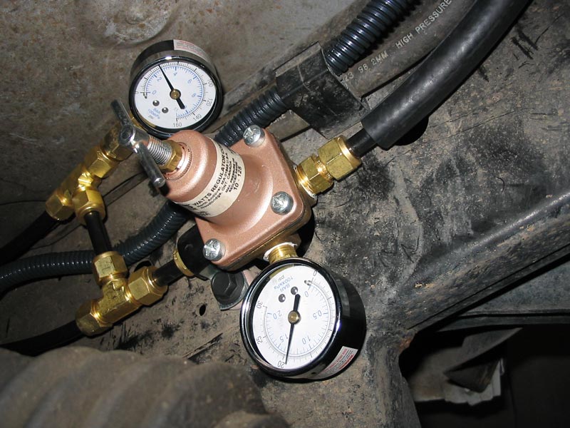
Frame rail setup:

Pressure gauges installed on frame rail at engine idle:
3/8" fitting that replaced the banjo bolt on the filter housing:

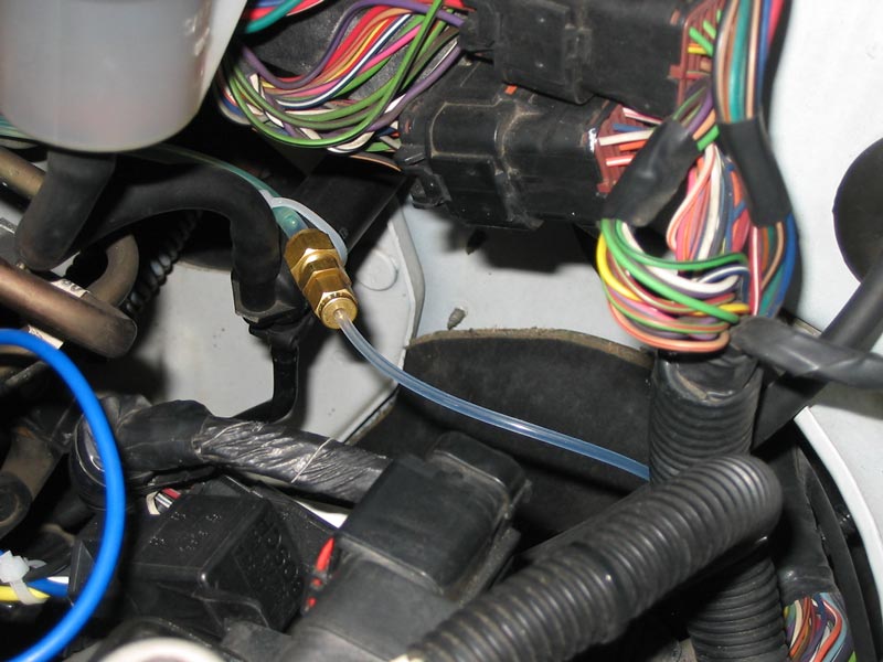
The pressure line from fuel filter is adapted to 1/8" to bring it into the cab:
Parts used:
Surplus Center:
1 2140-160 160 PSI 2" LM DRY GAUGE $4.69
1 2140-30 30 PSI 2" LM DRY GAUGE $4.69
E-bay:
1 Bosch 20/30 amp SPDT 12 VDC relay $5
1 Walbro GSL392 gerotor pump with clamps and fittings $114
MSC Industrial:
30' 74203779 .275IDX3/8ODX.050WALL NYLON11 TUBE(CTL)BLACK $23.10
1 04254371 1/4NPT X M12 METRIC ISO ADAPTER $4.88
Swagelok:
2 3/8" brass Tee $6
2 3/8" NPTM to 3/8" Swagelok tube $3
1 1/4" NPTM to 3/8" tube stub (adapts the fuel filter adapter to tube) $2.50
1 3/8" Swagelok elbow $6
1 1/4" NPTF to 3/8" barb fitting (goes on bypass valve, optional) $3
1 1/4" NPTF to 3/8" Swagelok (goes on bypass valve, optional) $2
10 3/8" Swagelok ferrule set (did not need any but had for spares) $6
1 1/8" to 1/4" Swagelok reducing union (for cab gauge) $3
2 1/8" Swagelok cap/ferrule sets (for cab gauge) $2
4' 1/8" PTFE tubing (this I had, didn't buy) $10
Hardware store:
1/8" NPTM to 1/4" Parker compression needle valve (cab fuel gauge disconnect) $5 (replace the rubber O-ring on this with Buna-N; I used #3 Viton O-ring)
NAPA auto parts:
5' 3/8" fuel hose $5
1 3003 3/8" Napa Gold inline fuel filter $3.69
2 5/16" 665-1147 or 665-1989 self tapping frame bolts, pkg of 5 and 10 $5 per package
1 3/4" 770-1160 Adel clamps $6
4' 1/2" water hose for Nylon hose sheath in the engine compartment $4
Misc. parts:
1 Teflon-sealed needle valve for adjusting return flow (from a friend, any valve will work)
Wal-Mart:
20' 14 gauge wire, black and red, $5
Blue crimp terminals and 3/8" split loom $5
The 263A Watts pressure regulator that I used has a Buna-N diaphragm and is designed for water or heating oil pressure control. I had it in my parts box, didn't have to buy it. This actually was part of the reason I did it this way instead of using a back pressure regulator like the one in the Glacier kit. A 26 Watts is the same as the 263 but does not have a gauge fitting (I have two of those but the gauges are neat so I used the 263 for bragging rights)
The fuel filter housing fittings are all 3/8" throughout, performance gurus will like that.
I may have forgotten a few small parts. If anybody needs detailed advice, please PM me and I will answer with details.
Notes:
The clear housing of the inline filter allows me to see bursts of air bubbles coming in. I am not sure what that is caused by; all clamps seem very tight. With any other strainer with a metal housing you would simply not know this is happening. I will look into this; the truck does not seem to care.
I have tons of fittings left over; well, I bought way more than I used up simply to save the trip to Denver Valve and Fitting (Swagelok dealer). BTW, they will ship Swagelok to you if you are not local.
I have probably 15' of nylon-11 left over. This is considering I used it for bench testing and for the return line. You don't need 30' to implement this setup.
I did not have to drill any holes in the frame. There are perfectly spaced holes in the frame already, forward of the transfer case (you can see the location on the pictures). Same applied to mounting of the pressure regulator: I used existing holes for everything. A Napa 5/16" self tapping bolt with fine thread works great for this.
The pressure at idle can be set to anything using the Watts. I set it to 17 psi and there is a 2 psi drop across the line and filter (the cab gauge reads 17, frame rail reads 19 psi). At WOT the pressure is 12 psi. At rapid and heavy acceleration it can drop to 10. This is all with high pressure set to 40 psi. If I bump this to 60 psi using the bypass valve, the heavy acceleration does not drop below 13 psi. But 10 is fine with me, so I backed it off to 40 psi to relieve the GSL392.
I plan to bolt a slightly angled steel shield, like a skid plate, to the bottom of the frame rail to protect the setup from debris kicked up by the tires.
Hope this helps!
-P
Anyway, here are the pictures I promised to post:
In-cabin mech. pressure gauge:
Frame rail setup:
Pressure gauges installed on frame rail at engine idle:
3/8" fitting that replaced the banjo bolt on the filter housing:
The pressure line from fuel filter is adapted to 1/8" to bring it into the cab:
Parts used:
Surplus Center:
1 2140-160 160 PSI 2" LM DRY GAUGE $4.69
1 2140-30 30 PSI 2" LM DRY GAUGE $4.69
E-bay:
1 Bosch 20/30 amp SPDT 12 VDC relay $5
1 Walbro GSL392 gerotor pump with clamps and fittings $114
MSC Industrial:
30' 74203779 .275IDX3/8ODX.050WALL NYLON11 TUBE(CTL)BLACK $23.10
1 04254371 1/4NPT X M12 METRIC ISO ADAPTER $4.88
Swagelok:
2 3/8" brass Tee $6
2 3/8" NPTM to 3/8" Swagelok tube $3
1 1/4" NPTM to 3/8" tube stub (adapts the fuel filter adapter to tube) $2.50
1 3/8" Swagelok elbow $6
1 1/4" NPTF to 3/8" barb fitting (goes on bypass valve, optional) $3
1 1/4" NPTF to 3/8" Swagelok (goes on bypass valve, optional) $2
10 3/8" Swagelok ferrule set (did not need any but had for spares) $6
1 1/8" to 1/4" Swagelok reducing union (for cab gauge) $3
2 1/8" Swagelok cap/ferrule sets (for cab gauge) $2
4' 1/8" PTFE tubing (this I had, didn't buy) $10
Hardware store:
1/8" NPTM to 1/4" Parker compression needle valve (cab fuel gauge disconnect) $5 (replace the rubber O-ring on this with Buna-N; I used #3 Viton O-ring)
NAPA auto parts:
5' 3/8" fuel hose $5
1 3003 3/8" Napa Gold inline fuel filter $3.69
2 5/16" 665-1147 or 665-1989 self tapping frame bolts, pkg of 5 and 10 $5 per package
1 3/4" 770-1160 Adel clamps $6
4' 1/2" water hose for Nylon hose sheath in the engine compartment $4
Misc. parts:
1 Teflon-sealed needle valve for adjusting return flow (from a friend, any valve will work)
Wal-Mart:
20' 14 gauge wire, black and red, $5
Blue crimp terminals and 3/8" split loom $5
The 263A Watts pressure regulator that I used has a Buna-N diaphragm and is designed for water or heating oil pressure control. I had it in my parts box, didn't have to buy it. This actually was part of the reason I did it this way instead of using a back pressure regulator like the one in the Glacier kit. A 26 Watts is the same as the 263 but does not have a gauge fitting (I have two of those but the gauges are neat
so I used the 263 for bragging rights)The fuel filter housing fittings are all 3/8" throughout, performance gurus will like that.
I may have forgotten a few small parts. If anybody needs detailed advice, please PM me and I will answer with details.
Notes:
The clear housing of the inline filter allows me to see bursts of air bubbles coming in. I am not sure what that is caused by; all clamps seem very tight. With any other strainer with a metal housing you would simply not know this is happening. I will look into this; the truck does not seem to care.
I have tons of fittings left over; well, I bought way more than I used up simply to save the trip to Denver Valve and Fitting (Swagelok dealer). BTW, they will ship Swagelok to you if you are not local.
I have probably 15' of nylon-11 left over. This is considering I used it for bench testing and for the return line. You don't need 30' to implement this setup.
I did not have to drill any holes in the frame. There are perfectly spaced holes in the frame already, forward of the transfer case (you can see the location on the pictures). Same applied to mounting of the pressure regulator: I used existing holes for everything. A Napa 5/16" self tapping bolt with fine thread works great for this.
The pressure at idle can be set to anything using the Watts. I set it to 17 psi and there is a 2 psi drop across the line and filter (the cab gauge reads 17, frame rail reads 19 psi). At WOT the pressure is 12 psi. At rapid and heavy acceleration it can drop to 10. This is all with high pressure set to 40 psi. If I bump this to 60 psi using the bypass valve, the heavy acceleration does not drop below 13 psi. But 10 is fine with me, so I backed it off to 40 psi to relieve the GSL392.
I plan to bolt a slightly angled steel shield, like a skid plate, to the bottom of the frame rail to protect the setup from debris kicked up by the tires.
Hope this helps!
-P

Registered User
Joined: Dec 2001
Posts: 1,246
Likes: 1
From: Saint Ignatius, MT
Question for Paul.
In your fuel filter pic... I see you are use the stock banjo and fuel line to the vp. Would removal of the banjo bolt and a larger line to the vp change any of your findings?
Your write up is still digesting in my brain but saw that pic and made me wonder.
Nice info guys.
In your fuel filter pic... I see you are use the stock banjo and fuel line to the vp. Would removal of the banjo bolt and a larger line to the vp change any of your findings?
Your write up is still digesting in my brain but saw that pic and made me wonder.
Nice info guys.
Registered User
Joined: Feb 2007
Posts: 292
Likes: 1
From: New England
Very nice Paul. That system looks like a good one and has plenty of reserve capacity if you want to make big HP.
I cant believe how rust free your 98 is. Here in New England, everything under the hood on my 98 is coated with corrosion.
I cant believe how rust free your 98 is. Here in New England, everything under the hood on my 98 is coated with corrosion.
Thread Starter
Registered User
Joined: Nov 2006
Posts: 1,491
Likes: 3
From: Longmont, CO
Question for Paul.
In your fuel filter pic... I see you are use the stock banjo and fuel line to the vp. Would removal of the banjo bolt and a larger line to the vp change any of your findings?
Your write up is still digesting in my brain but saw that pic and made me wonder.
Nice info guys.
In your fuel filter pic... I see you are use the stock banjo and fuel line to the vp. Would removal of the banjo bolt and a larger line to the vp change any of your findings?
Your write up is still digesting in my brain but saw that pic and made me wonder.
Nice info guys.
I did not replace the last set of banjo fittings. I am sure replacing these would further open up fuel supply to the VP44 and reduce the WOT pressure drop. The cost to replace this last line would be less than $20 (fittings). On my stock HP truck I don't feel the need for this, WOT pressures are well within specs.
Also, the ultimate solution is not even replacing this line. Instead, pressure regulator should be put in the line right before the IP. This way the pump's high pressure will be overcoming the pre-IP restrictive lines, not the 17 psi that comes off the frame rail mounted regulator I have.
This idea is not new, Superduty advocated this well before me. The advantage is obvious: pressure regulator will deliver set pressure directly to the IP, and pressure drop in the short line is very small. Increased flow through the fuel filter housing is easier to produce at higher pressure.
This is best done using a back pressure regulator (or high flow pressure relief / bypass valve via a separate return line). My setup with a forward pressure regulator won't work very well because if I let full pump pressure at fuel filter housing, it will blow the lid for sure, or cave in the filter element; I would have to decide on the max allowed pressure and bypass the rest with a valve... what a mess. Back pressure regulator is the way to go.
-P
Thread Starter
Registered User
Joined: Nov 2006
Posts: 1,491
Likes: 3
From: Longmont, CO
Bent_valves - Thanks! I only bought the truck last November, and it was painted black underneath by the dealer. Cosmetic improvements I guess. It looked like a new truck on the lot. The rust is beginning to show through now, but the metal down there is half inch think, I think it will last . But still, you are right, it is in very good shape.
-P
. But still, you are right, it is in very good shape.-P