
Chicken lights


Thread Starter
Registered User
Joined: Mar 2005
Posts: 170
Likes: 0
From: Union Grove WI.
Chicken lights
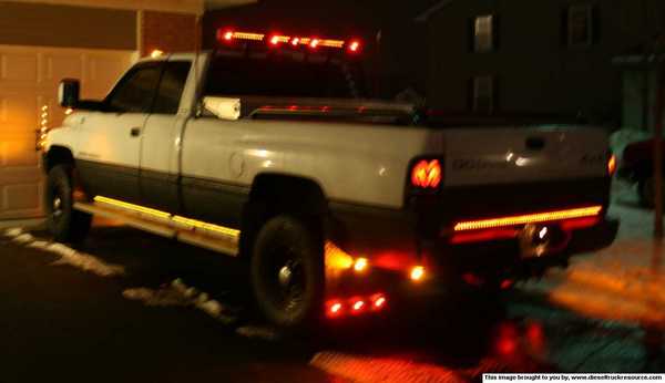
I've been thinking about putting some amber lights on my rocker panels, front bumper, and headache rack. Im wondering how to hook them up. Can I just splice into the parking light wires or do I need to run relays or should I run them on a toggle switch?
I wish I was as fine, as those who work the pipeline!
Joined: Dec 2008
Posts: 1,639
Likes: 0
From: Wyoming
Depends on how many you want to add. The electrical system is not 'over' designed. I believe the brake and parking light circuit does have some extra room so you can plug in a trailer. You could test the circuit with a volt meter to see what the draw is and compare it to the wire length to see what the circuit can handle.
If it were me I would add a circuit and relays. I generally try to stay away from wire harnesses and splicing, but that is just my personal preference. You could splice into your parking light circuit to activate the relay for your new lights but then the new amber's would be on all the time. Maybe activate them with the fog lights?
If it were me I would add a circuit and relays. I generally try to stay away from wire harnesses and splicing, but that is just my personal preference. You could splice into your parking light circuit to activate the relay for your new lights but then the new amber's would be on all the time. Maybe activate them with the fog lights?

Registered User
Joined: Jul 2007
Posts: 426
Likes: 0
From: Fremont, OH/Newport News, VA
I ran relays for mine. But I also have quite a few additional lights. I tapped the parking light wire to activate the relay, but put a switch inline with that wire so I can still turn them off manually if I want. That also makes it nice, you can't accidentally leave em on, they shut off with the stock lights.
Thread Starter
Registered User
Joined: Mar 2005
Posts: 170
Likes: 0
From: Union Grove WI.
Ok that sounds easy enough, What size relay would I need for 45-50 lights? Im not real good with electrical stuff, I can hook it up but figuring out what I need is a little foggy for me. thanks

I wish I was as fine, as those who work the pipeline!
Joined: Dec 2008
Posts: 1,639
Likes: 0
From: Wyoming
You will also need to size your wire correctly and take into account line loss for the given gauge of wire, for a particular length.
So -> ((watts/volts) - line loss) = circuit amps
I would design the circuit at 75% - 80% to avoid any strain or excess heat.
Sp -> ((watts/volts) - line loss) x .75 = designed circuit amps
You can decrease line loss by increasing wire size, or decreasing wire length within a circuit. Line length is the longest run of wire from the source to the last item on the circuit when there is a single wire run. When there are multiple wire runs the effect of line loss is cumulative.
((100 watts / 12 volts) - line loss) x .75 at a 5% line loss this would require a 6 amp circuit.
(8.33 - .42) x 75% = 5.9 Amps
Make sense? Made this post pretty quick, so if I have made a mistake, chime in guys.

Thread
Thread Starter
Forum
Replies
Last Post
sakisaki400
3rd Generation Ram - Non Drivetrain - All Years
19
Jan 14, 2007 07:36 PM
PurNLoud
3rd Gen High Performance and Accessories (5.9L Only)
10
Jan 31, 2006 12:30 AM