
How to install Front LED Turn Signals


Thread Starter
Administrator


Joined: Nov 2004
Posts: 4,084
Likes: 235
From: Southern California
How to install Front LED Turn Signals
Part-1
I made a few more changes to my truck.
It has sound, turn it up!
I don�t know why my truck looks squished in the pictures.


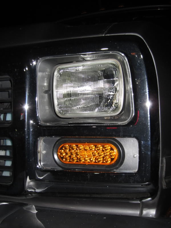
Well, what do the think; they are bright when you are facing them head on.
Finally the big mystery is uncovered!
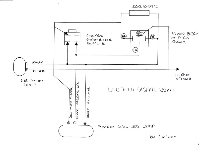
As anyone who has tried to install LED�s in both your front turn signal and also your front corner lamps you will soon find out that the corner lamps will no longer work properly and flash in cadence with the turn signal, this is because back when using the incandescent lamps, the corner lamp was made to burn steady and blink by connecting the filament across both the turn and the parking lamp hot leads, LED�s will no longer work this way because they are a solid state device and not allow current to flow in the opposite direction.
So to overcome this problem I devised a way using a simple SPDT relay, now all of the LED�s will work as before.
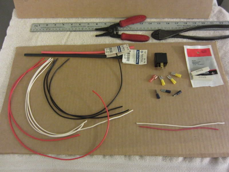
Materials List:
You will need to make 2 of these, one for each side.
2) 30-amp Bosch/ Tyco Relays
6) 10-gauge Female Spade Connectors (Yellow)
2) 16-gauge Female Spade Connectors (Red)
6) �� Male Spade Terminals
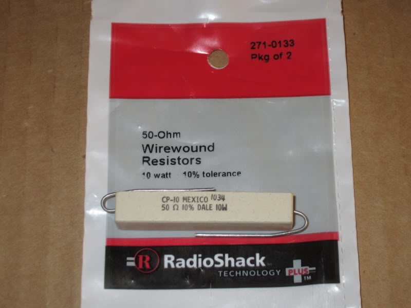
2) 50 ohm 10-watt wirewound resistors (Radio Shack # 271-0133)
16-gauge stranded automotive wire:
2) 12� pieces of Red wire
2) 12� pieces of Black wire
2) 12� pieces of White wire
2) 16� pieces of Red wire
4) 16� pieces of Black wire
4) 16� pieces of White wire
20-gauge stranded automotive wire:
2) 4� pieces of Red wire
2) 4� pieces of White wire
Also you will need:
Wire strippers
Good crimping pliers
Assorted �� Shrink Tubing
8� of 1� shrink tubing
Soldering Iron
Rosin Core Solder
Heat Gun
Tie Wraps (zip ties)
Misc. lengths of convoluted tubing of expanding tubing.
Materials for light:
2) Amber Stop/ Turn Oval LED Truck light with pigtail
2) Mounting Grommets for lights
Scrap of 1/8� or 3/16� aluminum sheet
4) #8 Stainless steel sheet metal screws
You will also need a Scroll Saw with appropriate (fine tooth) metal cutting blades.
Electric drill and drill bits.
Let�s get started.
First set yourself up a good clean place to work and set out all of the parts in front of you, I will build then one at a time.
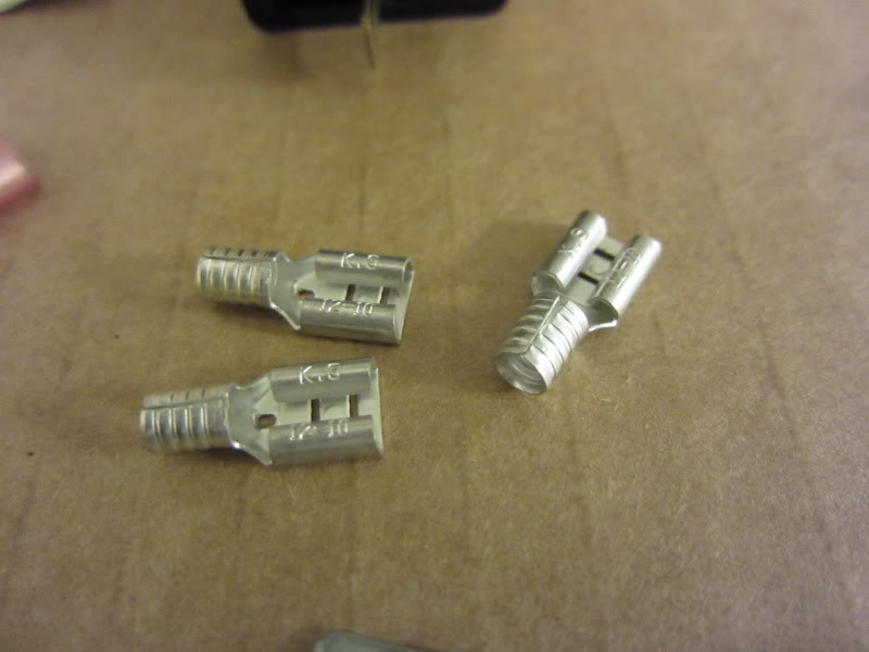
First we must modify the 3) 10-gauge female terminals by holding the terminal ends carefully with pliers and then gently remove the yellow insulating jacket and discard them.
Take the 16�, 16�, 12� and 4� white wire and with the ends stripped back 3/8� insert all 4 of the wires into one of the #10-gauge terminals and using your crimpers crimp them tightly, we will solder these later.
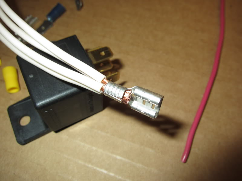
For now slip the white wires onto Term. #85 of the relay.
Take one of the 16� Black wires and strip and crimp on the Red 14-gauge Female Spade connector and then slip this onto Term. #87a
Next take a 12� and the 16� Black wire and after stripping them insert them into the #10-gauge female connector and using the crimper carefully crimp them.
Notice how I close one tab down first and then fold the remaining tab over then crimp the flat. (you may not be able to do this with your particular style crimpers; I only use Sta-Kon by Thomas & Betts.
When you are finished, slip this onto Term. #30 of the Relay.
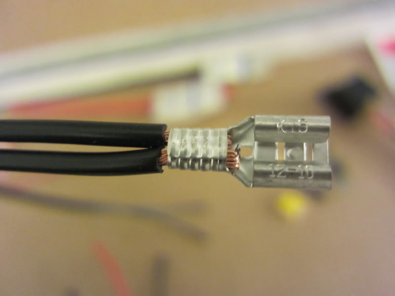
Now take the 12�, 16� and 4� Red wires and after stripping them insert all of them into the #10-gauge female connector, again see how I fold the tabs over onto each other.

Now you can slip the red wires onto Term. #86 of the Relay.
I made a few more changes to my truck.
It has sound, turn it up!
I don�t know why my truck looks squished in the pictures.
Well, what do the think; they are bright when you are facing them head on.
Finally the big mystery is uncovered!
As anyone who has tried to install LED�s in both your front turn signal and also your front corner lamps you will soon find out that the corner lamps will no longer work properly and flash in cadence with the turn signal, this is because back when using the incandescent lamps, the corner lamp was made to burn steady and blink by connecting the filament across both the turn and the parking lamp hot leads, LED�s will no longer work this way because they are a solid state device and not allow current to flow in the opposite direction.
So to overcome this problem I devised a way using a simple SPDT relay, now all of the LED�s will work as before.
Materials List:
You will need to make 2 of these, one for each side.
2) 30-amp Bosch/ Tyco Relays
6) 10-gauge Female Spade Connectors (Yellow)
2) 16-gauge Female Spade Connectors (Red)
6) �� Male Spade Terminals
2) 50 ohm 10-watt wirewound resistors (Radio Shack # 271-0133)
16-gauge stranded automotive wire:
2) 12� pieces of Red wire
2) 12� pieces of Black wire
2) 12� pieces of White wire
2) 16� pieces of Red wire
4) 16� pieces of Black wire
4) 16� pieces of White wire
20-gauge stranded automotive wire:
2) 4� pieces of Red wire
2) 4� pieces of White wire
Also you will need:
Wire strippers
Good crimping pliers
Assorted �� Shrink Tubing
8� of 1� shrink tubing
Soldering Iron
Rosin Core Solder
Heat Gun
Tie Wraps (zip ties)
Misc. lengths of convoluted tubing of expanding tubing.
Materials for light:
2) Amber Stop/ Turn Oval LED Truck light with pigtail
2) Mounting Grommets for lights
Scrap of 1/8� or 3/16� aluminum sheet
4) #8 Stainless steel sheet metal screws
You will also need a Scroll Saw with appropriate (fine tooth) metal cutting blades.
Electric drill and drill bits.
Let�s get started.
First set yourself up a good clean place to work and set out all of the parts in front of you, I will build then one at a time.
First we must modify the 3) 10-gauge female terminals by holding the terminal ends carefully with pliers and then gently remove the yellow insulating jacket and discard them.
Take the 16�, 16�, 12� and 4� white wire and with the ends stripped back 3/8� insert all 4 of the wires into one of the #10-gauge terminals and using your crimpers crimp them tightly, we will solder these later.
For now slip the white wires onto Term. #85 of the relay.
Take one of the 16� Black wires and strip and crimp on the Red 14-gauge Female Spade connector and then slip this onto Term. #87a
Next take a 12� and the 16� Black wire and after stripping them insert them into the #10-gauge female connector and using the crimper carefully crimp them.
Notice how I close one tab down first and then fold the remaining tab over then crimp the flat. (you may not be able to do this with your particular style crimpers; I only use Sta-Kon by Thomas & Betts.
When you are finished, slip this onto Term. #30 of the Relay.
Now take the 12�, 16� and 4� Red wires and after stripping them insert all of them into the #10-gauge female connector, again see how I fold the tabs over onto each other.
Now you can slip the red wires onto Term. #86 of the Relay.
Thread Starter
Administrator
Joined: Nov 2004
Posts: 4,084
Likes: 235
From: Southern California
Part-2
Now take all of the crimped connections and using at least a 100-watt soldering gun and Rosin Core solder carefully solder all of the connections being careful not to get the solder into the terminal or you will have problems getting the terminal over the blade of the relay.
Then cut about 1� of �� shrink tubing and slip it over the terminal and wire.
Using your heat gun carefully allow it to shrink tightly onto the terminal and wire, do this for all of the terminals.
Now reinstall the wires onto the relay:
3) Red wires Term. #86 (+)
4) White wires Term. #85 (-)
Single Black wire Term. #87a
2) Black wires Term. #30
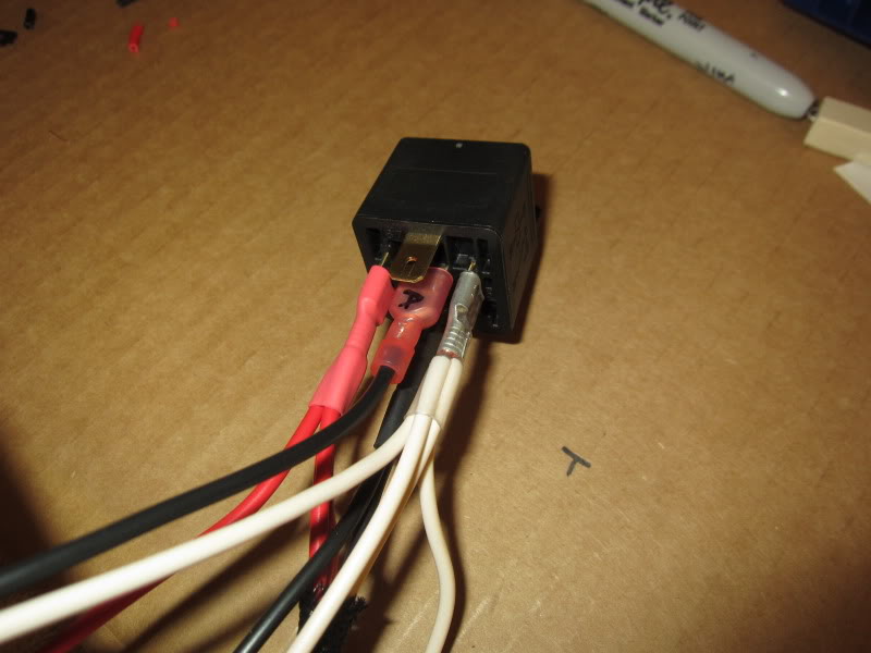
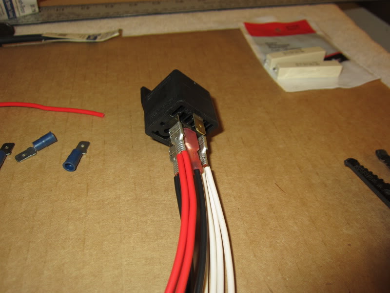
Now pay attention, secure the relay so it does not move with the wires facing down.
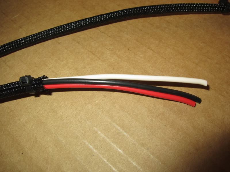
Take the 3 short 12� Red (Term. #86), Black (Term. #30) and White (Term. #85) wires and arrange them into 1 bundle.
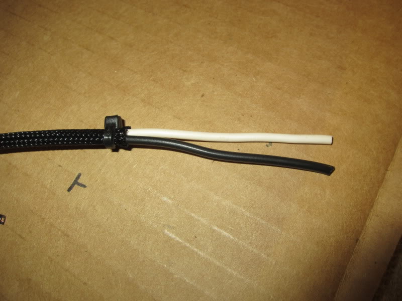
Take one 16� White wire from Term. #85 and the 16� Black wire from Term. #87a and tie them into one bundle.
Take the remaining 16� Red (Term. #86), Black (Term. #30) and White (Term. #85) wires and make another bundle.
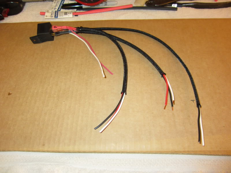
Here I used expanded tubing to cover my wires, you could use convoluted tubing or simply tape them using good Scotch-33 electrical tape.
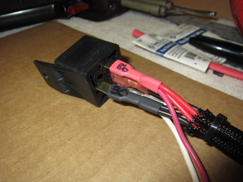
Close-up of the relay, I then identified the terminals and marked them using a Sharpie.
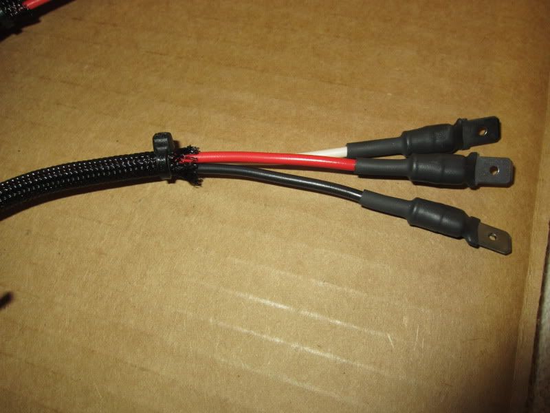
To the ends of the Red, Black and White 16� bundle you now crimp on male spade terminals to each of the 3 wires.
Please ignore the length of MY wire harness.
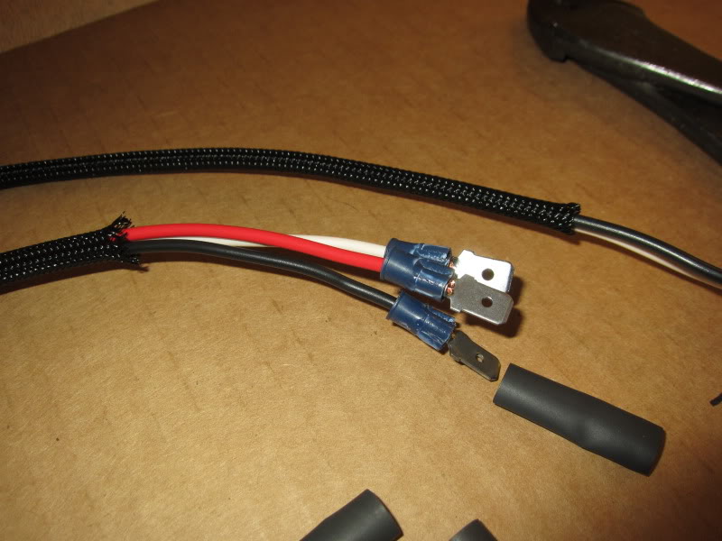
Now again using �� shrink tubing shrink it over the ends of the spade terminals like so.
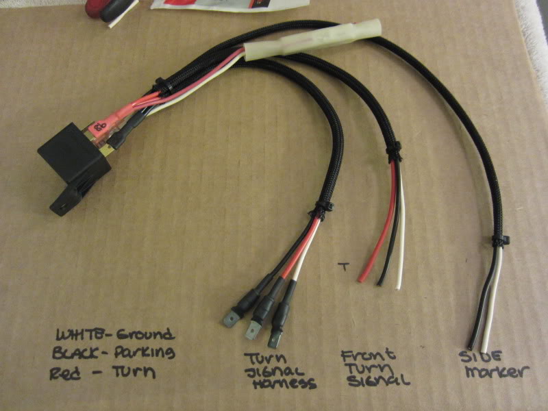
It should look something like this when you are done.
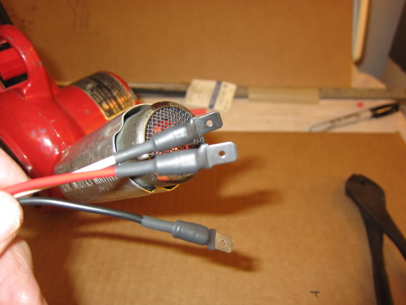
These 3 wires will be connected to your factory harness. Red (Turn) Black (Parking) White (ground)
These 2 wires are now going to feed your LED corner lamps, Black (+)
White (-)
The 3 shorter 12� wires are for the new LED signal lamp. Red (Turn) Black (Parking) White (ground)
Now take all of the crimped connections and using at least a 100-watt soldering gun and Rosin Core solder carefully solder all of the connections being careful not to get the solder into the terminal or you will have problems getting the terminal over the blade of the relay.
Then cut about 1� of �� shrink tubing and slip it over the terminal and wire.
Using your heat gun carefully allow it to shrink tightly onto the terminal and wire, do this for all of the terminals.
Now reinstall the wires onto the relay:
3) Red wires Term. #86 (+)
4) White wires Term. #85 (-)
Single Black wire Term. #87a
2) Black wires Term. #30
Now pay attention, secure the relay so it does not move with the wires facing down.
Take the 3 short 12� Red (Term. #86), Black (Term. #30) and White (Term. #85) wires and arrange them into 1 bundle.
Take one 16� White wire from Term. #85 and the 16� Black wire from Term. #87a and tie them into one bundle.
Take the remaining 16� Red (Term. #86), Black (Term. #30) and White (Term. #85) wires and make another bundle.
Here I used expanded tubing to cover my wires, you could use convoluted tubing or simply tape them using good Scotch-33 electrical tape.
Close-up of the relay, I then identified the terminals and marked them using a Sharpie.
To the ends of the Red, Black and White 16� bundle you now crimp on male spade terminals to each of the 3 wires.
Please ignore the length of MY wire harness.
Now again using �� shrink tubing shrink it over the ends of the spade terminals like so.
It should look something like this when you are done.
These 3 wires will be connected to your factory harness. Red (Turn) Black (Parking) White (ground)
These 2 wires are now going to feed your LED corner lamps, Black (+)
White (-)
The 3 shorter 12� wires are for the new LED signal lamp. Red (Turn) Black (Parking) White (ground)
Thread Starter
Administrator
Joined: Nov 2004
Posts: 4,084
Likes: 235
From: Southern California
Part-3
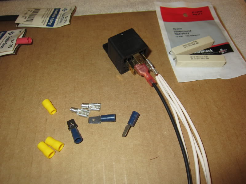
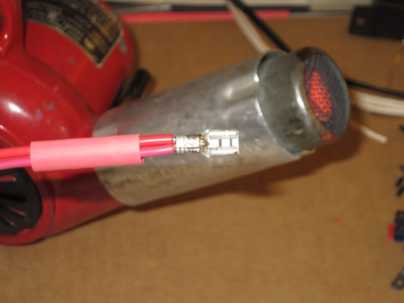
Next we are going to add some resistance into the circuit, I could have used a diode to keep the relay coil from chattering but by using a 50-ohm 10-watt wirewound resistor it suppresses the chatter and it will add enough load to the circuit for the turn signal flasher to work.
This was purchased from my local Radio Shack.
Carefully fold the leads around the body as I have and after you tin the ends of the Red and White 20-gauge wire, solder them as I have.
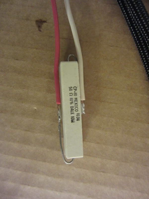
This is how it should look when you are finished, I purposely left the leads long so in the future I could experiment with the resistance if needed and also gives you more flexibility when mounting the relay.
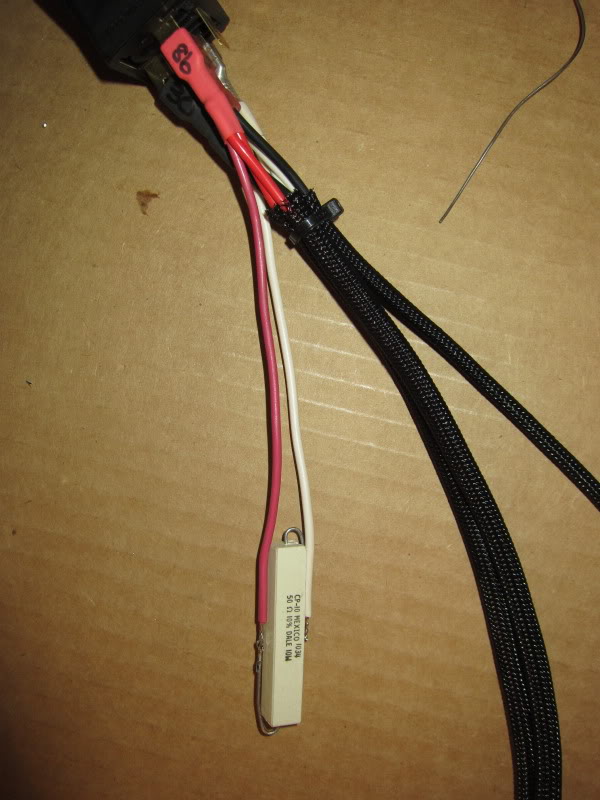
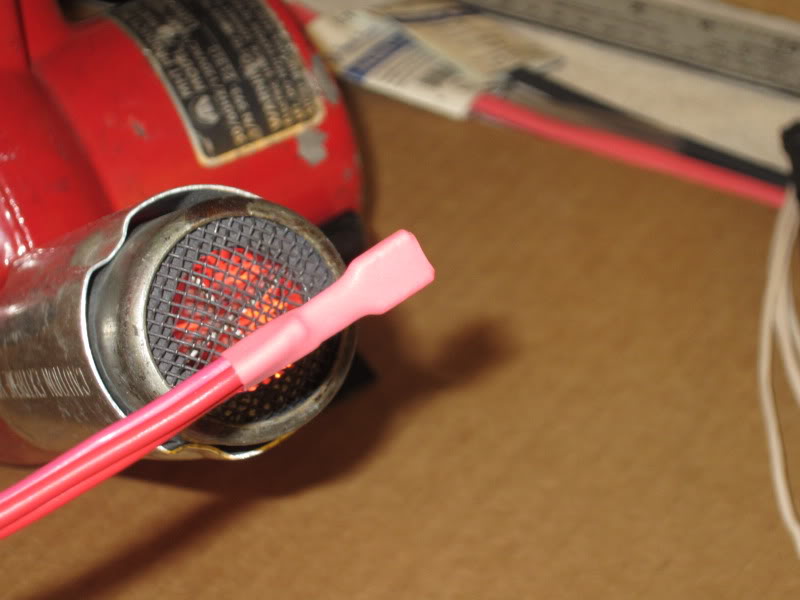
Now all you need to do is to take your 4� piece of 1� diameter shrink tubing and center the resistor in side of it, then using heat shrink it down to protect it.
You can see here how the leads are arranged and what device they are connected to.
Now you need to make one more assembly.
Now you will see how to mount the lights.
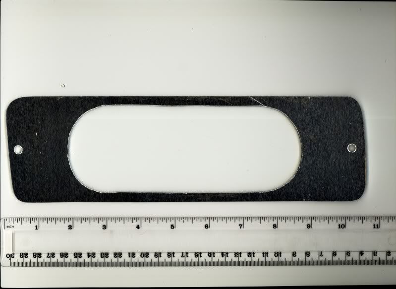
I made a template from the light housing and transferred it to a scrap of 3/16� aluminum; I also have a full size template in PDF you can download.
Using my scroll saw and some good Bosch metal cutting blades I first drilled a 3/8� hole so I could star the blade for the inside cut, I cut it against a 4�X16� block of wood so it was easier to handle .
I just held it using my knee and went slow and it cut easily.
When you cut out the inside do it accurately, if the hole is too big then the grommet and light will be loose.
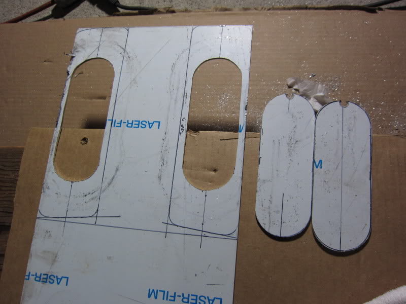
I used my 4� Makita Angle Grinder with a metal disk and carefully cut the radius on each end while making test fits until it fit the housing to my liking.
Sorry, I know the truck is dirty because it had just rained.
Take you time and do a good job.
My Brother-in-law owns a machine shop; I am going to see if he would use the CNC and make me some out of � aluminum.
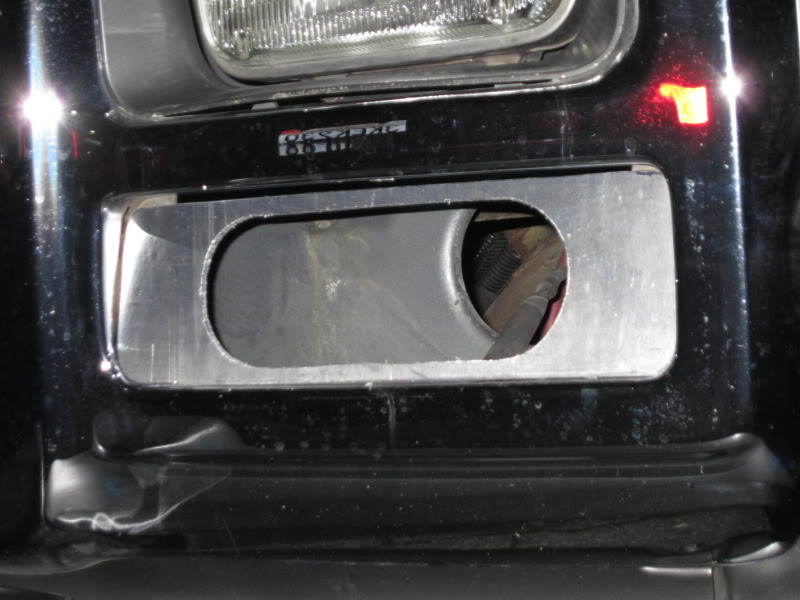
After they were both made I installed the grommet into the adapter and then squeezed in the lamp module for a test run.
They will be painted a dark metallic paint when I am finished to match the headlight bezels.
I mounted each relay assembly behind each turn signal and pulled the corner light wires and relay trigger wires through the opening.
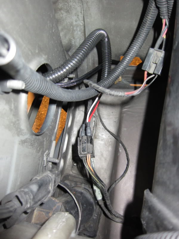
When you disconnect and remove the factory turn signal housings this 4 pin terminal is where you will connect your trigger, there will be one on each side behind the headlamp.
Looking straight at it with the lock tab on the top:
Red wire terminal is inserted into the top left.
White wire terminal is inserted into the bottom left.
Black wire terminal is inserted into the bottom right
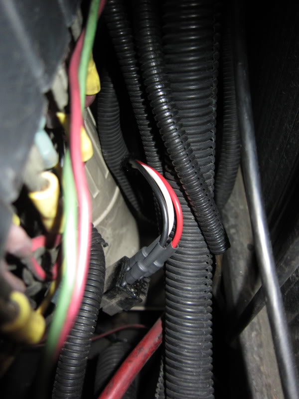
I connected my lights to the relay wires using crimp terminals and applied shrink tubing over them.
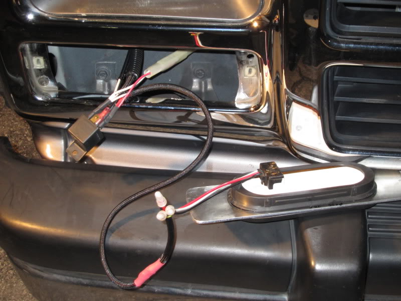
Here is the connection on the passenger side, make sure to dress the wiring out of the way when you are finished.
Hey there is my jack that I haven�t been looking for.
If at any time you want to remove the lights simply unplug the relays and reconnect the stock housings.
If you want to use the #1157 LED modules in place of the oval lamps you will need to splice the 3 trigger wires into the wires of the lamp assembly, every thing else will be the same.
Feel free to change any of the wire lengths to suit your particular application.
Next we are going to add some resistance into the circuit, I could have used a diode to keep the relay coil from chattering but by using a 50-ohm 10-watt wirewound resistor it suppresses the chatter and it will add enough load to the circuit for the turn signal flasher to work.
This was purchased from my local Radio Shack.
Carefully fold the leads around the body as I have and after you tin the ends of the Red and White 20-gauge wire, solder them as I have.
This is how it should look when you are finished, I purposely left the leads long so in the future I could experiment with the resistance if needed and also gives you more flexibility when mounting the relay.
Now all you need to do is to take your 4� piece of 1� diameter shrink tubing and center the resistor in side of it, then using heat shrink it down to protect it.
You can see here how the leads are arranged and what device they are connected to.
Now you need to make one more assembly.
Now you will see how to mount the lights.
I made a template from the light housing and transferred it to a scrap of 3/16� aluminum; I also have a full size template in PDF you can download.
Using my scroll saw and some good Bosch metal cutting blades I first drilled a 3/8� hole so I could star the blade for the inside cut, I cut it against a 4�X16� block of wood so it was easier to handle .
I just held it using my knee and went slow and it cut easily.
When you cut out the inside do it accurately, if the hole is too big then the grommet and light will be loose.
I used my 4� Makita Angle Grinder with a metal disk and carefully cut the radius on each end while making test fits until it fit the housing to my liking.
Sorry, I know the truck is dirty because it had just rained.
Take you time and do a good job.
My Brother-in-law owns a machine shop; I am going to see if he would use the CNC and make me some out of � aluminum.
After they were both made I installed the grommet into the adapter and then squeezed in the lamp module for a test run.
They will be painted a dark metallic paint when I am finished to match the headlight bezels.
I mounted each relay assembly behind each turn signal and pulled the corner light wires and relay trigger wires through the opening.
When you disconnect and remove the factory turn signal housings this 4 pin terminal is where you will connect your trigger, there will be one on each side behind the headlamp.
Looking straight at it with the lock tab on the top:
Red wire terminal is inserted into the top left.
White wire terminal is inserted into the bottom left.
Black wire terminal is inserted into the bottom right
I connected my lights to the relay wires using crimp terminals and applied shrink tubing over them.
Here is the connection on the passenger side, make sure to dress the wiring out of the way when you are finished.
Hey there is my jack that I haven�t been looking for.
If at any time you want to remove the lights simply unplug the relays and reconnect the stock housings.
If you want to use the #1157 LED modules in place of the oval lamps you will need to splice the 3 trigger wires into the wires of the lamp assembly, every thing else will be the same.
Feel free to change any of the wire lengths to suit your particular application.
Thread Starter
Administrator
Joined: Nov 2004
Posts: 4,084
Likes: 235
From: Southern California
Part-4
Here is a diagram of the relay circuit.
Here is a full sized template, for the opposite side you need to turn it over.
Also if you send an e-mail I can send you a full size template in a PDF file.
If you have any questions please feel free to ask.
Jim
Here is a diagram of the relay circuit.
Here is a full sized template, for the opposite side you need to turn it over.
Also if you send an e-mail I can send you a full size template in a PDF file.
If you have any questions please feel free to ask.
Jim

Registered User
Joined: Mar 2011
Posts: 20
Likes: 0
Hey Jim, superb write-up!
I did the LED conversion myself, but I didn't experience the corner lamp problem you described.
Instead of installing whole new oval LED lights like you did, I just popped amber 1157 LED bulbs in the stock housings, and amber 914's in the corner lamps.
My only issue was the flasher relay, but stretching the armature spring a little made it work.
Registered User
Joined: Jul 2009
Posts: 118
Likes: 0
From: Oklahoma


I put LED lights in my fenders a while back, and I like them alot better. I had LED bulbs in there before, but it make the turn signal indicator lights in the dash stay lit with the markers. I just ran a separate ground for these, hooked the turn signal to the turn signal side,and the marker to the marker side. The good thing was, I had these in a storage container with a bunch of other LED lights for my Peterbilt.
Thread Starter
Administrator
Joined: Nov 2004
Posts: 4,084
Likes: 235
From: Southern California
Hey,
I like those but I would really have a hard time cutting that big hole in my fender.
I am trying to find a way to add some front cornering lamps.
The only thing that I do not like about my particular Truck Lite is there is hardly any peripheral light spilled from these lamps compared to the stock housings also the way they are mounted they are canted off to the sides by a few degrees so they do light up off to the sides of the truck, but most of the beam(s) are focused straight ahead, although the beam froward is rather intense, when I come down my street at night and the signal is on the turn signal cast a bright amber spot on the neighbors house 75 feet away.
Defiantly a heck lot brighter that the stock lights though.
It is really noticeable when I get behind a nice shiny stainless steel trailer in front of me on the freeway.
Next time I go the the Light House I will check out other brands.
Still to come:
I am going to install LED's on my mirrors and a closed circuit camera to my video system on the right side of the truck inside the mirror housing to help with the blind spot.
Jim
Trending Topics

Registered User
Joined: Nov 2009
Posts: 1,955
Likes: 2
From: McCook, Nebraska
That dark metallic on the headlight bezels is called argent, if it's original. Totally auto has it in rattle cans. Prepare to say ouch when you see the price, though.
http://www.totallyautoinc.com/
http://www.totallyautoinc.com/
Registered User
Joined: Oct 2008
Posts: 351
Likes: 0
From: Dallas, GA
Nice piece, Jim. Sticky worthy, IMO.
As I have mentioned before here, I am in the construction business and have been for a long time. That being said, the fact that you made those cuts with a 4" grinder with a cut-off wheel is absolutely unbelievable. That took a steady hand. Very impressive, as usual.
I must ask, how many relays (total) have you added to your truck at this point?

Registered User
Joined: Mar 2005
Posts: 1,167
Likes: 2
From: SW Pennsylvania - Greene County
Nice work Jim! It's nice to see that I'm not the only one who still believes in soldering terminals to wire ends.
If I might add one small additional tip for those of us here in the rust belt. A dab of electrical contact grease or silicon based electrical grease to all of the terminal connection points will help in maintaining the longevity of the connections and aid in the future disconnecting of a relay should it ever need to be replaced.
If I might add one small additional tip for those of us here in the rust belt. A dab of electrical contact grease or silicon based electrical grease to all of the terminal connection points will help in maintaining the longevity of the connections and aid in the future disconnecting of a relay should it ever need to be replaced.
Thread Starter
Administrator
Joined: Nov 2004
Posts: 4,084
Likes: 235
From: Southern California
Nice piece, Jim. Sticky worthy, IMO.
As I have mentioned before here, I am in the construction business and have been for a long time. That being said, the fact that you made those cuts with a 4" grinder with a cut-off wheel is absolutely unbelievable. That took a steady hand. Very impressive, as usual.
As I have mentioned before here, I am in the construction business and have been for a long time. That being said, the fact that you made those cuts with a 4" grinder with a cut-off wheel is absolutely unbelievable. That took a steady hand. Very impressive, as usual.
I have worked in electrical/ electronics field in some capacity for the last 55 years, I have been a diesel mechanic/ truck/ automotive electrician, in my current position I work on HVAC, plumbing, electrical, alarm/ CCTV, telecommunications, CATV, and I take much pride in my work.
I have the the gift of logic, someone can describe a problem and I can diagnose it without seeing it because I know how something should work.
Actually quite a few comment on the quality of my work
I also like to study about medicine.
I have also done construction including all of the room additions to our house, my family owned construction companies, my uncle taught construction and and my dad was an electrical engineer.
It is nice to be able to do everything.
I must ask, how many relays (total) have you added to your truck at this point?
Wow that is a good question, let me think about this without going out to the truck, it's 3:00 A.M.
Under Hood:
2) Blower Motor
1) A/C Cycling Switch
2) LED turn signals
4) Headlamps
2) Cooling Fans
1) Marker Light Flash 4PDT (alarm)
3) Contactors (battery control)
Under Dash:
1) Fuse Panel Ignition control
1) ICC Flash
1) Starter Interlock
1) Starter Interrupt (alarm)
4) Door Locks (alarm)
2) Alarm functions
Back of truck:
1) Auxiliary Back up lights
1) Ventilating blower
1) Air Compressor
28 relays....

Wow I think this may have gotten out of hand, I am sure I might have missed a few though.


Registered User
Joined: Apr 2024
Posts: 4
Likes: 0
Hey Jim, superb write-up!
I did the LED conversion myself, but I didn't experience the corner lamp problem you described.
Instead of installing whole new oval LED lights like you did, I just popped amber 1157 LED bulbs in the stock housings, and amber 914's in the corner lamps.
My only issue was the flasher relay, but stretching the armature spring a little made it work.
I did the LED conversion myself, but I didn't experience the corner lamp problem you described.
Instead of installing whole new oval LED lights like you did, I just popped amber 1157 LED bulbs in the stock housings, and amber 914's in the corner lamps.
My only issue was the flasher relay, but stretching the armature spring a little made it work.

Registered User


Joined: Oct 2005
Posts: 6,457
Likes: 95
From: KENTUCKY
Nice write-up and nice approach and conversion.
I read everything twice.
It is probably there and I missed it --- brand and model number of the front LED lights.
Also, what was used in the side markers and were the side marker lens retained as delivered ?
I actually prefer replacement LED "bulbs", whether in the original housing or in a custom housing; reason(s) being, with any of those self-contained LED assemblies pretty soon one or more of the little light thingies is going to quit working; or worse, start flickering, requiring replacement of the entire assembly; plus, to keep things looking the same on both sides, you are faced with either sourcing the same brand/model or replacing both sides whenever one goes bad or gets damaged.
As for the Relays, I like to use so that replacing a relay is a "plug-n-play" endeavor.

Thread
Thread Starter
Forum
Replies
Last Post
pulltilbroke
1st Gen. Ram - All Topics
31
Jun 29, 2011 10:38 PM