
so help my tune my next set of twins on paper

Thread Starter
Registered User
Joined: Oct 2006
Posts: 3,142
Likes: 0
From: Okotoks AB
I can weld it.
But can you use paint and draw it, I have a tough time visualizing things like that.
I am going to try and get this. You are going to cut off the current "air filter ring" and then we will weld in a new piece that is the same diameter as the inducer. This will connect to the rest of your charge pipe via V-band clamp?
If that is the case, I like that idea, as I really think it will help to keep the velocity up. Vs going 3" and right at the turbo stepping it up to 4"
this is all just my speculation of what I know about hydraulics. I'll have to sit down with the brains and put my engineer hat on and figure out how to get that in there with out permanently damage.
I'm thinking cut the air filter ring off cleanly. thread some large NPT threads on the OD of the inducer. have adapter cone cut with matching FNPT threads. master tig the filter ring back on the compressor housing. now there can be adapter or no adapter in 30 seconds with a pipe wrench.
I don't know anything about paintshop photoshop junk. so picture it a nice 6-8" long gentle taper from the pipe size to the inducer size. whatever the actual dimentions are doesnt really matter right now. just getting the theory down.
Registered User
Joined: Jun 2006
Posts: 954
Likes: 0
From: Airdrie, AB
LOL, all I can picture is shoving a 3" OD pipe in there, welding it up, and then taking a die grinder to smooth out the transition. 
But that would require cutting off the air filter flange... Though your idea of threads is very intriguing.
But that would require cutting off the air filter flange... Though your idea of threads is very intriguing.

The Guru
Joined: Jan 2004
Posts: 6,589
Likes: 0
From: Airdrie Canada
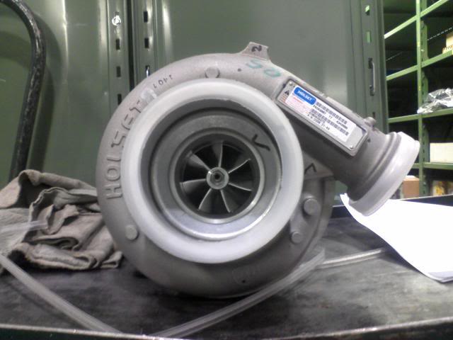
I would leave on the compressor inlet flange. Its better to go in straight that have a bend, even a slight one. It evenly loads the impeller. The inlet is designed to provide the first transistion, do a little work to compressor the air. You do major changes, you could effect the performance of the compressor (I would guess that you would loose efficency and some of your pressure ratio). If you look, there is a tapper part, silencer ring, that guides the air into the eye of the compressor. The only thing better would to pre-swirl the air, kinda like inlet guide vane, using the air velocity to start the process of going into the compressor impeller.
Ideally you try to get the air to be as straight as possible going into the compressor. They call that laminar air flow, which the opposite of turbulent. You would be supprised on how much engineering goes into the inlet of the turbo. Also there is anti-surge bleed ports just under the silencer, basically it feeds pressurized air from the impeller tip back into the impeller eye. You can try it and see what happens, but thats my two cents.
Ideally you try to get the air to be as straight as possible going into the compressor. They call that laminar air flow, which the opposite of turbulent. You would be supprised on how much engineering goes into the inlet of the turbo. Also there is anti-surge bleed ports just under the silencer, basically it feeds pressurized air from the impeller tip back into the impeller eye. You can try it and see what happens, but thats my two cents.
Thread Starter
Registered User
Joined: Oct 2006
Posts: 3,142
Likes: 0
From: Okotoks AB
Mike theres no bends in my plan. I know laminar - same as hydraulics. thats why I want to do what I want to do.
I need to show you what I mean.
that silencer ring is not good enough IMO. its too steep of an angle.
and I get all the engineering that goes into this junk, but none of tht engineering is for pressurized air in. its based on an intake vacumee right. filter restriction factor. no engineer accounted for pressurized air going into the inducer i will bet on that.
So I think all the wizz bang thats engineered into the upside of the compressor is moot. because the intake side of the compressor housing was engineered for a different atmosphere than it sees in twins.
Registered User
Joined: Jun 2006
Posts: 954
Likes: 0
From: Airdrie, AB
I have always read, and done, go with the size of the primary outlet, but I also know that tractor guys have put way more $$$$ and time in then anybody in diesel performance... So now I'm just confused. I truly wonder if a person, or even a dyno would notice the difference if that is all that was changed...


Thread Starter
Registered User
Joined: Oct 2006
Posts: 3,142
Likes: 0
From: Okotoks AB
I suppose that TAG item is going in the right direction. but still thats only about an inch long by the looks of it? and I think the more major point to that item is the honeycomb in it.
see what i'm getting at is to transition from the 3 or 3.5 pipe to the inducer size over say a 6-8" length cone. to direct all the flow out of the intermediate pipe directly at the inducer. WITHOUT haveing the major turbulence created by that cavernous space that houses the inducer.
see what i'm getting at is to transition from the 3 or 3.5 pipe to the inducer size over say a 6-8" length cone. to direct all the flow out of the intermediate pipe directly at the inducer. WITHOUT haveing the major turbulence created by that cavernous space that houses the inducer.
The Guru
Joined: Jan 2004
Posts: 6,589
Likes: 0
From: Airdrie Canada
At work we have compressor that you can adjust the guide vanes angle forward and reverse. The guide angle help guide the air into the compressor, try to straighten out the air flow. You would be supprised how tuberlent that the air flow is the front of a compressor. I was thinking about copying some of my compressor text theory info and posting a PDF, some of the theory.
I'm not saying that it wont work, just stuff to be aware of. The same goes for the compressor housing, its job is to direct the air out of the impeller and finish off the last velocity leaving the compressor. The compressor housing machined surface that mates sorta up with impeller, has a tight tolerance. If you have to much clearance, air will not travel up to the tip and you'll be recycling air inside the compressor housing. Thats why gas compressor used shrouded impeller not open faced impellers. Thats my 2bits of compressor theory.
I'm not saying that it wont work, just stuff to be aware of. The same goes for the compressor housing, its job is to direct the air out of the impeller and finish off the last velocity leaving the compressor. The compressor housing machined surface that mates sorta up with impeller, has a tight tolerance. If you have to much clearance, air will not travel up to the tip and you'll be recycling air inside the compressor housing. Thats why gas compressor used shrouded impeller not open faced impellers.
Thats my 2bits of compressor theory.

Thread
Thread Starter
Forum
Replies
Last Post
Blake Clark
4th Gen High Performance and Accessories 2010 and Up
21
Aug 21, 2012 12:35 PM
highrpms
3rd Gen High Performance and Accessories (5.9L Only)
1
Mar 16, 2008 08:35 PM