
How to beat the box (step-by-step trailer turn wiring fix)

Thread Starter
Registered User
Joined: Feb 2006
Posts: 2,280
Likes: 10
From: Udaho
How to beat the box (step-by-step trailer turn wiring fix)
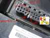
I spent last evening wiring an external relay to my IPM so I could get my right turn/brake signal back. It worked, except for I fried the relay when I soldered to it  . It's always energized now and has continuity between pins 30 and 87 (indication of a bad relay). So use female blade connectors instead of solder. It works just fine, but the relay is always charged and heats up after awhile. A new relay and blade connectors should fix the problem. Also, don't laugh too hard at my pictures- the work looks pretty kluged. This is a "bread board" experiment, I'll go back now and make it look good, now I know that it works, using better wire and some craftsmanship.
So here it goes:
Disclaimer: I make no claims that it will work for you, but it did for me (well sort of, see above). If hacking the electronics of your $40,000 truck makes you nauseous, please buy a new IPM instead of attempting this. The mod is for a 2003 CTD, but should work on the 2004 as well (should be same wiring). If you have another year of truck then you are on your own, but I imagine it can�t be that much different.
Definitions:
FCM-�Forward Control Module�, silver box on the side of the PCM.
IPM- �Integrated Power Module�, a combination of the FCM and PCM.
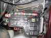
PCM- �Power Control Module�, a.k.a. �fuse box�.
Parts:
(1) Add-a circuit, mini blade fuse style. $4
(1) Micro Relay (sorry, dealer item only $13)
(2) Quick-splice
(4) mini-blade female connectors (not shown)
(~4�) of 18 ga wire
(3) zip ties for strain relief
Tools:
-Wire strippers & crimpers
- Dremel tool
- 13mm socket
- Phillips screwdriver
-1/2� open end wrench
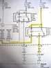
Wiring Diagram:
Process:
(Click on photos to enlarge, go here to my gallery to see closeups of the relay and Add-a-Circuit parts)
. It's always energized now and has continuity between pins 30 and 87 (indication of a bad relay). So use female blade connectors instead of solder. It works just fine, but the relay is always charged and heats up after awhile. A new relay and blade connectors should fix the problem. Also, don't laugh too hard at my pictures- the work looks pretty kluged. This is a "bread board" experiment, I'll go back now and make it look good, now I know that it works, using better wire and some craftsmanship.So here it goes:
Disclaimer: I make no claims that it will work for you, but it did for me (well sort of, see above). If hacking the electronics of your $40,000 truck makes you nauseous, please buy a new IPM instead of attempting this. The mod is for a 2003 CTD, but should work on the 2004 as well (should be same wiring). If you have another year of truck then you are on your own, but I imagine it can�t be that much different.
Definitions:
FCM-�Forward Control Module�, silver box on the side of the PCM.
IPM- �Integrated Power Module�, a combination of the FCM and PCM.
PCM- �Power Control Module�, a.k.a. �fuse box�.
Parts:
(1) Add-a circuit, mini blade fuse style. $4
(1) Micro Relay (sorry, dealer item only $13)
(2) Quick-splice
(4) mini-blade female connectors (not shown)
(~4�) of 18 ga wire
(3) zip ties for strain relief
Tools:
-Wire strippers & crimpers
- Dremel tool
- 13mm socket
- Phillips screwdriver
-1/2� open end wrench
Wiring Diagram:
Process:
- Remove neg. battery cables
- Remove power cable on side of PCM, disconnect single wire connector on left front of PCM. Remove (2) IPM fasteners, slide to the left to the clear the slots in the battery tray and tilt so you can access the FCM.
- Remove FCM (4 screws and pull outward).
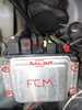
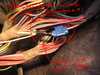
- Modify FCM connector (and PCM side) to allow you to smash a wire in pin 34 (right turn) or pin 14 (left turn). Carefully mate FCM to PCM, don't bend the pins.
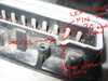
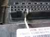
- On connector C1 under the PCM (the connector closest to the driver), tap the white wire w/pink stripe (right turn) or the dark green wire with the white stripe (left turn) with the quick-splice.
- Install the Add-a-Circuit in fuse 47 (right turn) or fuse 46 (left turn). Place fuse in top slot of Add-a-Circuit. Do not place a fuse in the bottom slot.
- Splice another wire into the red wire of the Add-a-Circuit, so there are two.
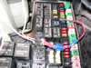
- Wire the Add-a-Circuit to pins 85 & 30 of the relay (power input).
- Wire pin 86 of the relay to the wire coming from the FCM (control).
- Wire pin 87 of the relay to the wire you spiced in C1 (output).

- Attach neg. battery cables & PCM power cable, test trailer connector at bumper.
- Secure everything, strain relieve, re-assemble.
(Click on photos to enlarge, go here to my gallery to see closeups of the relay and Add-a-Circuit parts)
Registered User
Joined: Jun 2006
Posts: 204
Likes: 0
From: Alberta, Canada
Ok, I seem to be having the same problem (see my post here.
I have no real electrical experience so this post reads like Greek to me. What is the underlying cause of the signal light outage? If I take it to the dealership will they re-wire it as above or is there an easier (probably more expensive) replacement that will fix the problem?
Thanks!
***Edit to add:
Should have done more reading. So I need a new IPM. If I order this part for my 2004, is it a simple plug and play replacement I can do myself or will it require programming or re-flashing by the dealership?
Also, is there anything I can do to help prevent this problem happening in the future or am I stuck crossing my fingers?
Thread Starter
Registered User
Joined: Feb 2006
Posts: 2,280
Likes: 10
From: Udaho
Should have done more reading. So I need a new IPM. If I order this part for my 2004, is it a simple plug and play replacement I can do myself or will it require programming or re-flashing by the dealership?
Also, is there anything I can do to help prevent this problem happening in the future or am I stuck crossing my fingers?
I'm fairly certain you can replace the IPM without a reflash. The hardest part would be disconnecting all the connectors, requires time and patience.
You may be able to prevent it from happening again by wiring fuses between the the trailer connector and the IPM, probably under the rear bumper. The engineers put the fuses before the relay and related circuitry, should've been after IMHO. Should be a simple splice job if you use these:
http://www.safco1.com/Images2007/Lar...Fuseholder.jpg
or
http://www.electronicplus.com/images/products/FH16X.jpg
(no guarantees it'll protect the internal trailer relays of your IPM, but it can't hurt either)
Thread Starter
Registered User
Joined: Feb 2006
Posts: 2,280
Likes: 10
From: Udaho
The turn/brakes lights use a 15amp fuse in the IPM, I guess you could go 10 and if the blow out a lot then swith to 15.
Trending Topics

Registered User
Joined: Apr 2006
Posts: 108
Likes: 0
From: Albuquerque
The original wiring diagram is the proper way to do things, with a fuse ahead of everything. Adding a fuse after the relay does not improve things.
The voltage at 85 should always be +VBattery. The voltage at 86 (pin 34 of FCM) should be +VBatt when turn signal light is off, and should be near GND (less than 1 volt) when turn signal light is on.
If the new relay is always energized, then either the relay is bad (you say you fried it during soldering) or FCM_34 is always GND, and the FCM is bad. This relay can be tested by disconnecting 86 (FCM_34). Does it de-energize?
If your relay replacement works, other than a melted relay due to excessive solder heat, then the FCM is OK and the factory turn signal relay is bad. I would expect that the factory relay could be replaced, just a matter of finding the suitable replacement from an electronics supply store.
Thread Starter
Registered User
Joined: Feb 2006
Posts: 2,280
Likes: 10
From: Udaho
The original wiring diagram is the proper way to do things, with a fuse ahead of everything. Adding a fuse after the relay does not improve things.
The voltage at 85 should always be +VBattery. The voltage at 86 (pin 34 of FCM) should be +VBatt when turn signal light is off, and should be near GND (less than 1 volt) when turn signal light is on.
If the new relay is always energized, then either the relay is bad (you say you fried it during soldering) or FCM_34 is always GND, and the FCM is bad. This relay can be tested by disconnecting 86 (FCM_34). Does it de-energize?
If your relay replacement works, other than a melted relay due to excessive solder heat, then the FCM is OK and the factory turn signal relay is bad. I would expect that the factory relay could be replaced, just a matter of finding the suitable replacement from an electronics supply store.
The voltage at 85 should always be +VBattery. The voltage at 86 (pin 34 of FCM) should be +VBatt when turn signal light is off, and should be near GND (less than 1 volt) when turn signal light is on.
If the new relay is always energized, then either the relay is bad (you say you fried it during soldering) or FCM_34 is always GND, and the FCM is bad. This relay can be tested by disconnecting 86 (FCM_34). Does it de-energize?
If your relay replacement works, other than a melted relay due to excessive solder heat, then the FCM is OK and the factory turn signal relay is bad. I would expect that the factory relay could be replaced, just a matter of finding the suitable replacement from an electronics supply store.
Oh good, someone who knows about this stuff! (I know just enough to be dangerous, as you probably noticed)
I installed a new relay last night and actually got the same results as the old (soldered) relay. It engergizes when I connect pin 86 to FCM_34. This of course makes pin 87 hot, and the right turn light is always on.
It goes without saying that if I connect to pin 87a instead, that everything works fine (only get signal to the right turn light when the blinkers are on), but the relay is still always energized so it heats up (that's bad I assume, don't want it to melt anything).
Based on the info you provided, I just went out and checked with a multimeter- FCM_34 is .14 VDC with the key off/blinkers off. I guess your'e saying I need a new FCM (unless there is a way to work around that as well?).
One other thing, the resistance between 85 & 86 is 94.5 Ohms on both the old and new relays. The spec is 67.5-82.5 Ohms. My guess is that discrepancy wouldn't cause the relay to engergize, right?
Also...just curious why a fuse downstream from the IPM wouldn't protect the relay and related circuitry? Couldn't a short in the trailer wiring potentially fry the FCM or relay before the OEM fuse blew?
(be gentle, I'm clueless when it comes to this stuff)
Thread Starter
Registered User
Joined: Feb 2006
Posts: 2,280
Likes: 10
From: Udaho
My dealer told me you couldn't order them separate, you had to get both as a unit. But he's been wrong before
. My guess is if you got one from a salvage yard you could buy them separate, but at the risk it's also bad.
Thread Starter
Registered User
Joined: Feb 2006
Posts: 2,280
Likes: 10
From: Udaho
 & get a new PCM to go with your old FCM.
You could use the method mentioned by NSXT to check the FCM, i.e. 12 volts on pins 34 (right turn) & 14 (left turn) when the blinkers are off, <1 volt when on, but there's no way to get a probe into those pins that I know of without butchering the parts and smashing a wire in there like I did
 .
.
Thread Starter
Registered User
Joined: Feb 2006
Posts: 2,280
Likes: 10
From: Udaho
I'm off now to vacation with the trailer sans right turn signal (gee officer, are you sure? I mean, it was working the last time I checked, gosh, thanks for letting me know. I'll get that fixed right away!).
Back Monday.
Adios!