
Go Ahead and Laugh now

Registered User
Joined: Mar 2005
Posts: 6,259
Likes: 1
From: Utah
From the book....
The combination, dual function Inlet Air Temperature/Pressure Sensor is located on the air cleaner (filter) cover.
The Inlet Air Temperature/Pressure Sensor is a combination dual-function sensor. The sensor element extends into the intake air stream at the top of the air filter housing. Ambient air temperature as well as barometric pressure is monitored by this sensor. The Engine Control Module (ECM) monitors signals from this sensor.

Registered User
Joined: Dec 2006
Posts: 209
Likes: 0
From the book....
The combination, dual function Inlet Air Temperature/Pressure Sensor is located on the air cleaner (filter) cover.
The Inlet Air Temperature/Pressure Sensor is a combination dual-function sensor. The sensor element extends into the intake air stream at the top of the air filter housing. Ambient air temperature as well as barometric pressure is monitored by this sensor. The Engine Control Module (ECM) monitors signals from this sensor.
The combination, dual function Inlet Air Temperature/Pressure Sensor is located on the air cleaner (filter) cover.
The Inlet Air Temperature/Pressure Sensor is a combination dual-function sensor. The sensor element extends into the intake air stream at the top of the air filter housing. Ambient air temperature as well as barometric pressure is monitored by this sensor. The Engine Control Module (ECM) monitors signals from this sensor.

I'm going to add a little bit to your explanation if you don't mind.
The fuel injection timing is subject to change due to the air temperature and air pressure readings from these sensors for efficiency and environmental reasons.
Does anyone have a good explanation or tutorial to post that explains how the fueling takes place with our Cummins engines?
It sure would help everyone!


Banned
Joined: Jan 2006
Posts: 2,756
Likes: 1
From: McDonough GA
From the book....
The combination, dual function Inlet Air Temperature/Pressure Sensor is located on the air cleaner (filter) cover.
The Inlet Air Temperature/Pressure Sensor is a combination dual-function sensor. The sensor element extends into the intake air stream at the top of the air filter housing. Ambient air temperature as well as barometric pressure is monitored by this sensor. The Engine Control Module (ECM) monitors signals from this sensor.
The combination, dual function Inlet Air Temperature/Pressure Sensor is located on the air cleaner (filter) cover.
The Inlet Air Temperature/Pressure Sensor is a combination dual-function sensor. The sensor element extends into the intake air stream at the top of the air filter housing. Ambient air temperature as well as barometric pressure is monitored by this sensor. The Engine Control Module (ECM) monitors signals from this sensor.
IIRC, the one in the air intake track is mainly used to determine how long to cycle the grid heaters and when they will kick in.
Registered User
Joined: Mar 2005
Posts: 6,259
Likes: 1
From: Utah
Thats one sensor, but, not the important one. The important one that will effect fueling, and get dirty, is located on the intake and is also a dual function sensor. The MAP/Intake Air Temp sensor is what the ECU uses to determine fueling curves.
IIRC, the one in the air intake track is mainly used to determine how long to cycle the grid heaters and when they will kick in.
IIRC, the one in the air intake track is mainly used to determine how long to cycle the grid heaters and when they will kick in.
The combination, dual function Intake Manifold Air Temperature Sensor/MAP Sensor is installed into the top of the intake manifold with the sensor element extending into the air stream.
The IAT portion of the sensor provides an input voltage to the Engine Control Module (ECM) indicating intake manifold air temperature. The MAP portion of the sensor provides an input voltage to the ECM indicating turbocharger boost pressure.
Registered User
Joined: Dec 2006
Posts: 209
Likes: 0
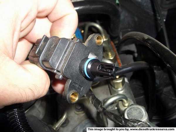
Here is the MAP sensor...
The combination, dual function Intake Manifold Air Temperature Sensor/MAP Sensor is installed into the top of the intake manifold with the sensor element extending into the air stream.
The IAT portion of the sensor provides an input voltage to the Engine Control Module (ECM) indicating intake manifold air temperature. The MAP portion of the sensor provides an input voltage to the ECM indicating turbocharger boost pressure.

Registered User

Joined: Jan 2004
Posts: 3,528
Likes: 16
From: Oregon
Here's what the combo manifold pressure/intake temp sensor on the intake manfold looks like. For what it's worth, it is totally spotless, and I idle with the Jacob on quite a bit.
I agree with what someone posted above, that pressure and temp sensors are generally less finicky than mass air flow sensors found on some gas engines, especially older ones.
I agree with what someone posted above, that pressure and temp sensors are generally less finicky than mass air flow sensors found on some gas engines, especially older ones.
Banned
Joined: Jan 2006
Posts: 2,756
Likes: 1
From: McDonough GA
Fueling curve is determind by boost, rpm, and APPS position. Altitude really has no effect other than slowing down spoolup which slows down the fuel curve.
The intake manifold air temp is used to determine auto high idle engagement and grid heater cycling.
The MAP sensor is pretty reliable on the CR engines but it can contribute to some weird issues if it is not working properly. It is a precision electronic component subjected extreme environmental effects. It can check out fine and have intermittent bad readings that contribute to wide range of issues.

Banned
Joined: May 2006
Posts: 3,660
Likes: 0
From: Florida
No, the intake air temp and barometric pressure sensor are predominately used to determine idle speed. Once the APPS produce a minimal signal they are out of the loop.
Fueling curve is determind by boost, rpm, and APPS position. Altitude really has no effect other than slowing down spoolup which slows down the fuel curve.
The intake manifold air temp is used to determine auto high idle engagement and grid heater cycling.
The MAP sensor is pretty reliable on the CR engines but it can contribute to some weird issues if it is not working properly. It is a precision electronic component subjected extreme environmental effects. It can check out fine and have intermittent bad readings that contribute to wide range of issues.
Registered User
Joined: Dec 2006
Posts: 209
Likes: 0
I wish someone would come up with a flow diagram listing sensors/inputs on the fuel injection timing on these Cummins engines. The electronics on these engines shouldn't be all that difficult if you understand the sensor functions.
Banned
Joined: May 2006
Posts: 3,660
Likes: 0
From: Florida
If I remember right, the MAP sensor is only in the loop at start up, just as he says - determining fuel curves for start up.
I wish someone would come up with a flow diagram listing sensors/inputs on the fuel injection timing on these Cummins engines. The electronics on these engines shouldn't be all that difficult if you understand the sensor functions.
I wish someone would come up with a flow diagram listing sensors/inputs on the fuel injection timing on these Cummins engines. The electronics on these engines shouldn't be all that difficult if you understand the sensor functions.
Registered User
Joined: Dec 2006
Posts: 209
Likes: 0
So here's a WAG - maybe one is for coarse adjustments to the fueling curve at start up, the other set for more precise adjustments due to finer parameters such as engine temperature changes, etc.


Banned
Joined: Jan 2006
Posts: 2,756
Likes: 1
From: McDonough GA
My understanding is the combo sensor on the air intake is used to determine barmometric pressure and ambient temp for idle characteristics. It is out of the loop after the APPS reaches a certain reading. I have a hard time believing the barometric pressure has anything to do with fueling due to the way the trucks act during altitude changes. I get more smoke and less power at higher altitudes, more power and less smoke at lower. Lack of oxygen causes that and there are no O2 sensors to modify fueling curves on the 5.9L.
Good luck on finding an accurate mapping of the sensors and there functions/effects without inside info. That is the software in the ECU and is more than likely considered proprietary info.
The engineers can tell you but they don't talk much here.
