


ZF hydraulic pump & hydro boost install


Thread Starter
Registered User
Joined: Apr 2007
Posts: 249
Likes: 0
From: East of Denver
ZF hydraulic pump & hydro boost install
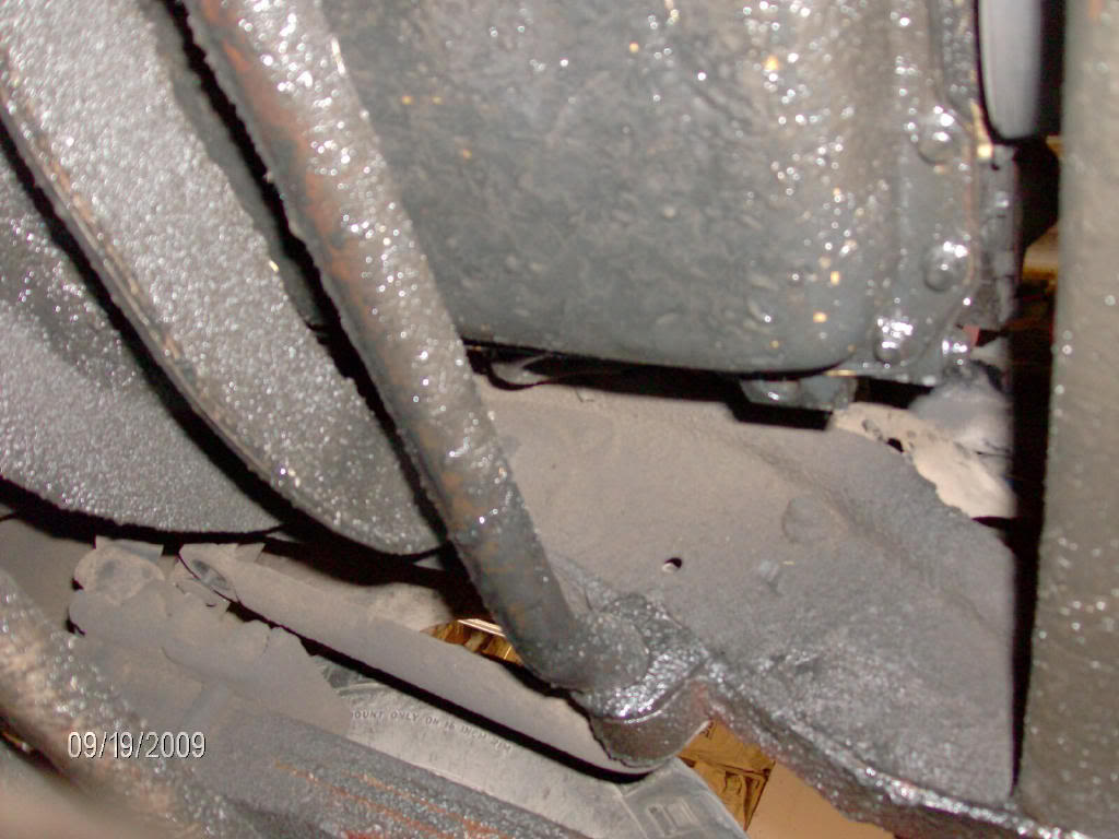
OK, this started out an an oil leak repair and got bigger from there. The factory vacuum pump/ steering pump had started leaking oil, very soon a lot of oil, 1 gallon in 3 days. I priced a replacement vacuum pump at well over $300 and my project began.
What oil leak?
After reading posts of how much better hydro boost brakes were compared to the factory vacuum booster I decided to fix it all at once.
I scrapped a Ford F600 a while back, after scrap weight I got paid $200 to keep the 140K Cummins that was in it. I also kept the hyrdaulic pump, power steering fluid reservior and a couple other little things.
I started assembling needed parts over the last 2-3 weeks, I used a GM hydro boost (fresh rebuild from another truck I scrapped) a new 1 ton GM master cylinder, the large ZF hydraulic pump, the external reservior and a power steering fluid cooler.
Also 9 feet of 6AN hose, 4- 6AN 90 degree hose ends, 3- power steering O ring fitting to 6AN adaters, 1- 8AN to 6AN adapter, 12 feet of 3/8" power steering return line and a 3/8" barbed end T.
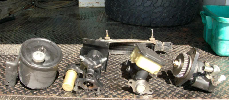
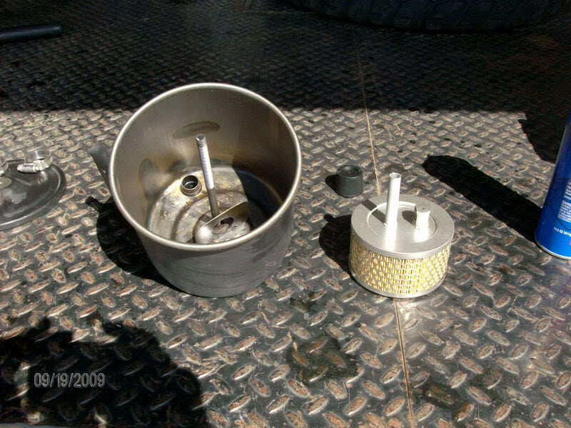
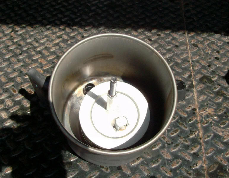
The power steering fluid reservior had a cool feature I found when I removed the top to clean it out, a filter, I got a new one from NAPA.
It did not take long to remove the vacuum/steering pump combination, I removed the vacuum line feeding the brake booster and the pressure line to the steering box. The hydro boost unit used a 6 AN feed line, so I used an 8 AN to 6 AN adapter on the pressure port of the pump. The vacuum/steering pump had pressurized oil feeding it, I installed a plug for now, it will feed my bypass filter soon.
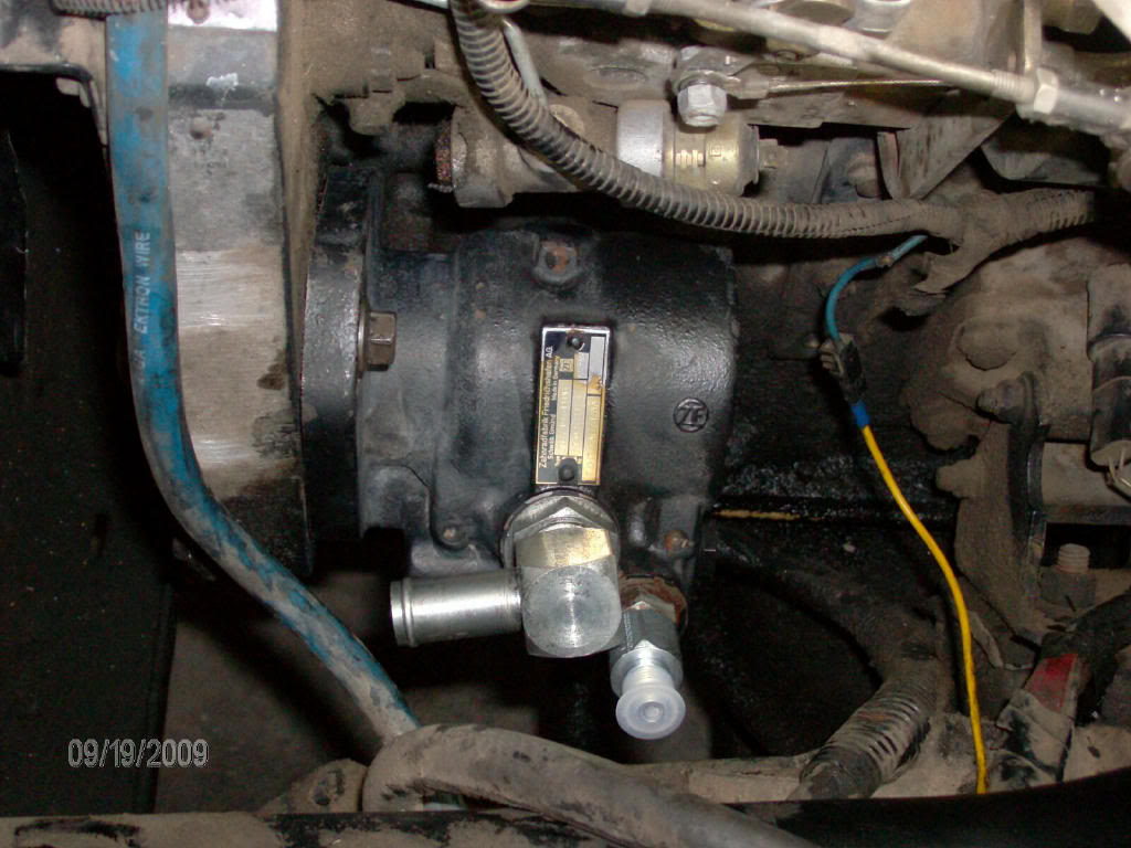
New pump installed.
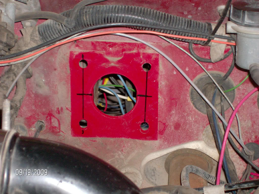
After removing the vacuum booster/master cylinder I began to lay out the new bolt holes. The GM hydro boost has 2 studs on the horizontal centerline, the same width as the stock holes. I laid them out using a straight edge. The lower 2 holes in the firewall will need to be transfered to the hydro boost mounting bracket. After I drilled the 2 centerline holes in the firewall I bolted up the hydro boost and marked the lower 2 holes from inside the cab. You could mark and drill the upper set of holes in to the hydro boost bracket, but I felt that 4 bolts was enough.
I found the actuator rod that attaches between the hydro boost and the brake pedal was 5/8 of an inch too long, I chose to cut and weld it to the proper length.
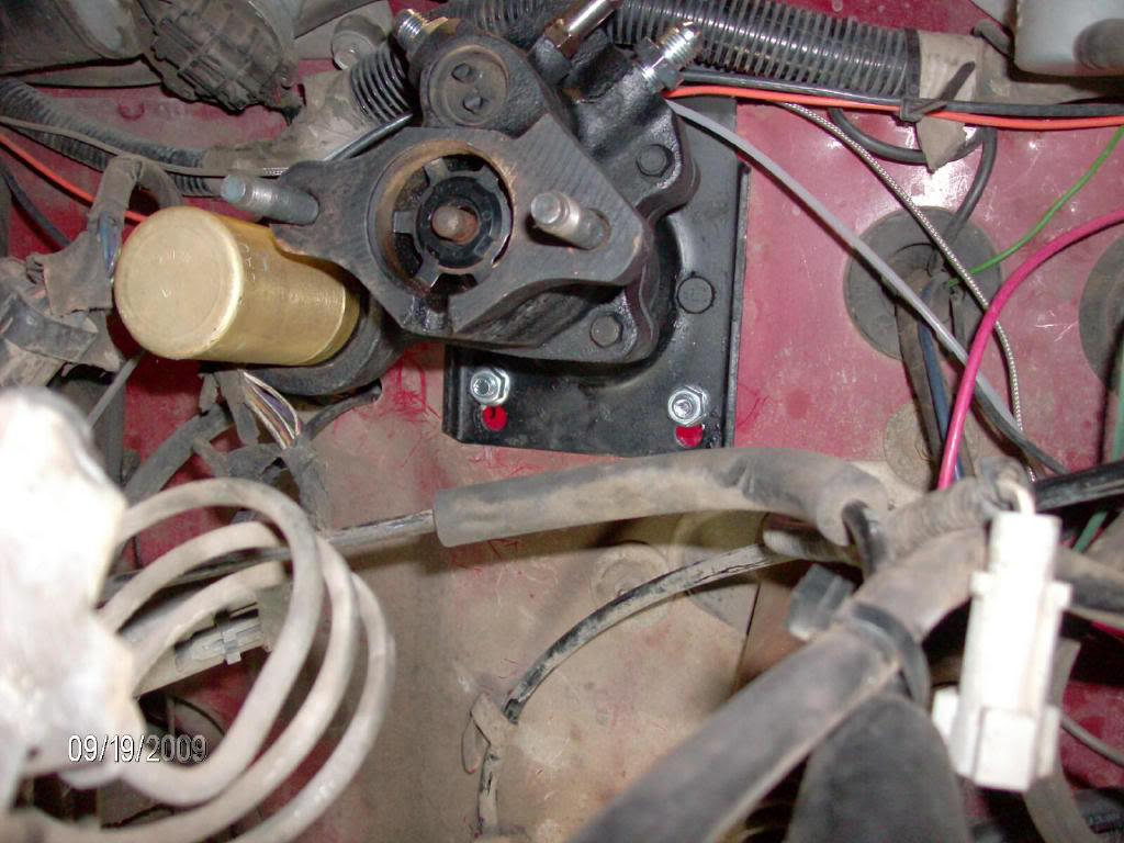
Hydro boost installed.
Next up plumbing the pressure and return lines.
What oil leak?
After reading posts of how much better hydro boost brakes were compared to the factory vacuum booster I decided to fix it all at once.
I scrapped a Ford F600 a while back, after scrap weight I got paid $200 to keep the 140K Cummins that was in it. I also kept the hyrdaulic pump, power steering fluid reservior and a couple other little things.
I started assembling needed parts over the last 2-3 weeks, I used a GM hydro boost (fresh rebuild from another truck I scrapped) a new 1 ton GM master cylinder, the large ZF hydraulic pump, the external reservior and a power steering fluid cooler.
Also 9 feet of 6AN hose, 4- 6AN 90 degree hose ends, 3- power steering O ring fitting to 6AN adaters, 1- 8AN to 6AN adapter, 12 feet of 3/8" power steering return line and a 3/8" barbed end T.
The power steering fluid reservior had a cool feature I found when I removed the top to clean it out, a filter, I got a new one from NAPA.
It did not take long to remove the vacuum/steering pump combination, I removed the vacuum line feeding the brake booster and the pressure line to the steering box. The hydro boost unit used a 6 AN feed line, so I used an 8 AN to 6 AN adapter on the pressure port of the pump. The vacuum/steering pump had pressurized oil feeding it, I installed a plug for now, it will feed my bypass filter soon.
New pump installed.
After removing the vacuum booster/master cylinder I began to lay out the new bolt holes. The GM hydro boost has 2 studs on the horizontal centerline, the same width as the stock holes. I laid them out using a straight edge. The lower 2 holes in the firewall will need to be transfered to the hydro boost mounting bracket. After I drilled the 2 centerline holes in the firewall I bolted up the hydro boost and marked the lower 2 holes from inside the cab. You could mark and drill the upper set of holes in to the hydro boost bracket, but I felt that 4 bolts was enough.
I found the actuator rod that attaches between the hydro boost and the brake pedal was 5/8 of an inch too long, I chose to cut and weld it to the proper length.
Hydro boost installed.
Next up plumbing the pressure and return lines.
Thread Starter
Registered User
Joined: Apr 2007
Posts: 249
Likes: 0
From: East of Denver
I will give a little bit of instruction on how I put the pressure lines together. Instead of trying to guess/measure hoses and have them built, I bought bulk hose and fittings and made them myself. The line has a layer of steel braid under rubber and a nylon/cloth type exterior jacket. It is 6AN, rated for 3000 PSI and is DOT certified, it is made by Aeroquip, the fittings were Aeroquip as well.
I like to start by installing 1 AN fitting on the hose, then attach it to one of the adapter fittings and route the other end of the line to where it will attach. This way you only need to worry about the clock/direction of one fitting and you get a more accurate idea of where to make the final cut.
When you cut any metal braided line you want to tightly wrap some tape around the place you need to cut. Also this hose does not have the ability to twist much, as you determine the length you need, you will also have to mark the direction you want the fitting to point.
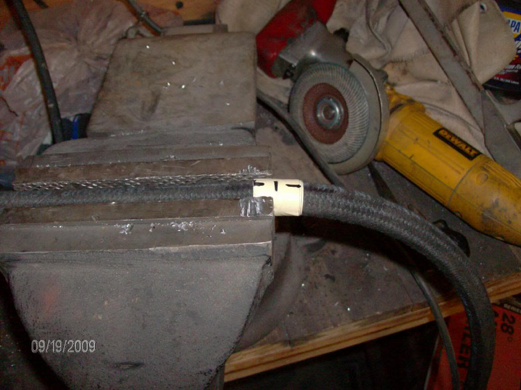
After the cut is made I transfer the clock marking to the hose with a soap stone, it will brush off when you are done, then remove the tape. Clamp the hose in the vice with the newly cut end sticking out, I like to use the estimated amount that will go inside the female portion of the AN fitting. This gives you a depth reference point when you are installing the female part of the AN fitting.
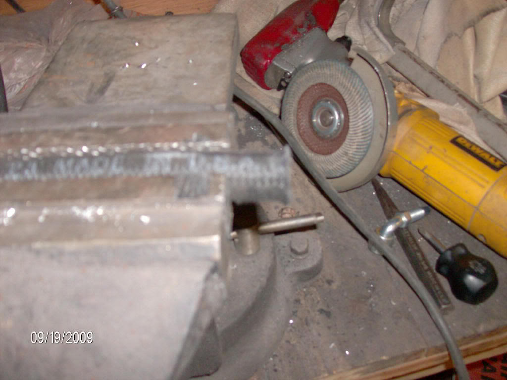
Now slip the female part over the end of the hose, tucking as much of the outer jacket and metal braid in as possible, if a lot of the material doubles over when you install the female part it makes it harder to get the fitting on.
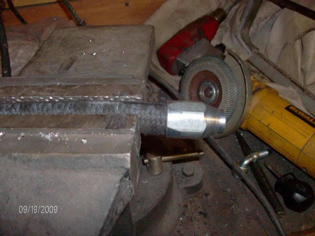
Here's a little trick I learned, use an impact wrench to install the female part. It can be done with a socket on a wratchet, but it takes a good bit of force, the impact makes it quick and easy.
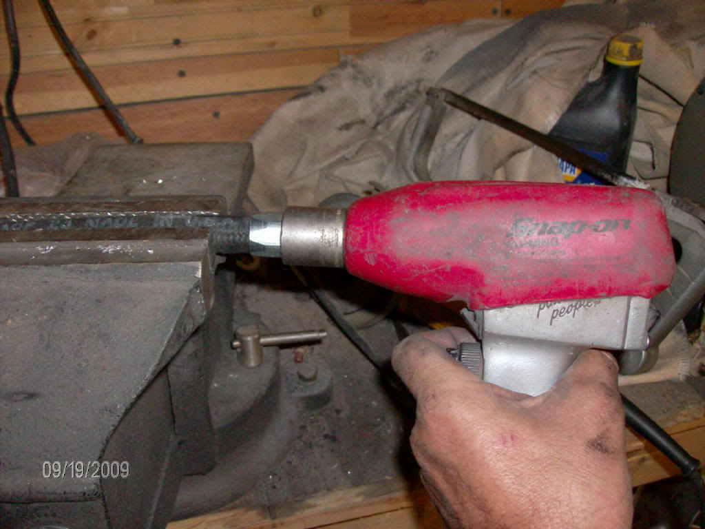
Do not go too far at first, run the female portion, which is threaded inside, down 1/2 to 3/4 of the estimated distance, then fit the male portion. you should feel the male end contact the hose when you start the first thread. If you do not feel the end hit the hose, tighten it on a little more untill you do. Ideally you want to have to gently force the male end into the hose to start the threads. Go a little at a a time because you do not want to back the fittings off. Lubricate the male end with some oil before final istallation
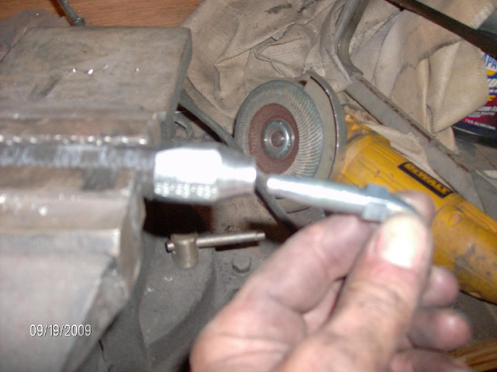
Thread the male end most of the way down, you will have the hold the female end with a wrench or put it in the vice to get it down the last bit. As you are tightening take note of how far the fitting moves per complete turn. Leave a small gap, equal to one full turn or more, between the 2 pieces of the fitting, this will allow you to adjust the clock of the fitting when you install it. ALWAYS TIGHTEN THE FITTING TO ADJUST IT, IF YOU LOOSEN IT WILL PROBABLY LEAK.
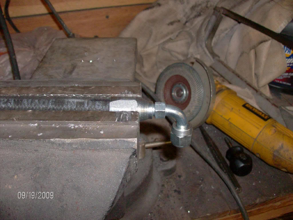
I like to start by installing 1 AN fitting on the hose, then attach it to one of the adapter fittings and route the other end of the line to where it will attach. This way you only need to worry about the clock/direction of one fitting and you get a more accurate idea of where to make the final cut.
When you cut any metal braided line you want to tightly wrap some tape around the place you need to cut. Also this hose does not have the ability to twist much, as you determine the length you need, you will also have to mark the direction you want the fitting to point.
After the cut is made I transfer the clock marking to the hose with a soap stone, it will brush off when you are done, then remove the tape. Clamp the hose in the vice with the newly cut end sticking out, I like to use the estimated amount that will go inside the female portion of the AN fitting. This gives you a depth reference point when you are installing the female part of the AN fitting.
Now slip the female part over the end of the hose, tucking as much of the outer jacket and metal braid in as possible, if a lot of the material doubles over when you install the female part it makes it harder to get the fitting on.
Here's a little trick I learned, use an impact wrench to install the female part. It can be done with a socket on a wratchet, but it takes a good bit of force, the impact makes it quick and easy.
Do not go too far at first, run the female portion, which is threaded inside, down 1/2 to 3/4 of the estimated distance, then fit the male portion. you should feel the male end contact the hose when you start the first thread. If you do not feel the end hit the hose, tighten it on a little more untill you do. Ideally you want to have to gently force the male end into the hose to start the threads. Go a little at a a time because you do not want to back the fittings off. Lubricate the male end with some oil before final istallation
Thread the male end most of the way down, you will have the hold the female end with a wrench or put it in the vice to get it down the last bit. As you are tightening take note of how far the fitting moves per complete turn. Leave a small gap, equal to one full turn or more, between the 2 pieces of the fitting, this will allow you to adjust the clock of the fitting when you install it. ALWAYS TIGHTEN THE FITTING TO ADJUST IT, IF YOU LOOSEN IT WILL PROBABLY LEAK.
Thread Starter
Registered User
Joined: Apr 2007
Posts: 249
Likes: 0
From: East of Denver
These connection points are for a GM hydro boost, I am not sure if other models are the same, but I expect they are.
The fitting at the 10 oclock position on the hydro boost is the pressure in line, it connects to the output on the pump. There is a 6AN to O ring adapter needed for the hydro boost end. With a 8AN to 6AN adapter at the pump.


The fitting at the 2 oclock position on the hydro boost is the pressure output to the steering box. both the hydro boost and the steering box use a 6AN to O ring adapter.
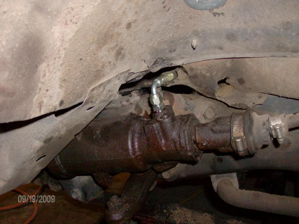
The remaining hose barb port on the hydro boost is the return line. I used a T fitting to connect the return line from the hydro boost and the return line from the steering box, I used the stock steel return line with a new piece of hose, I fed the output from the T to the power steering fluid cooler I mounted under the core support, behind my bumper. The cooler is not in direct air movement, but should do well enough with what it gets.
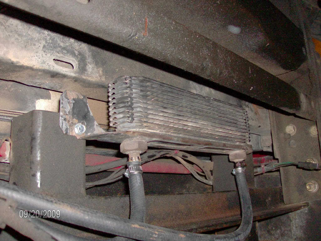
The output from the cooler then feeds into the fluid reservior. The reservior feeds the hydraulic pump through a 3/4 inch line. I made an L bracket and mounted it to the battery tray to hold the reservior. Here's the final product.
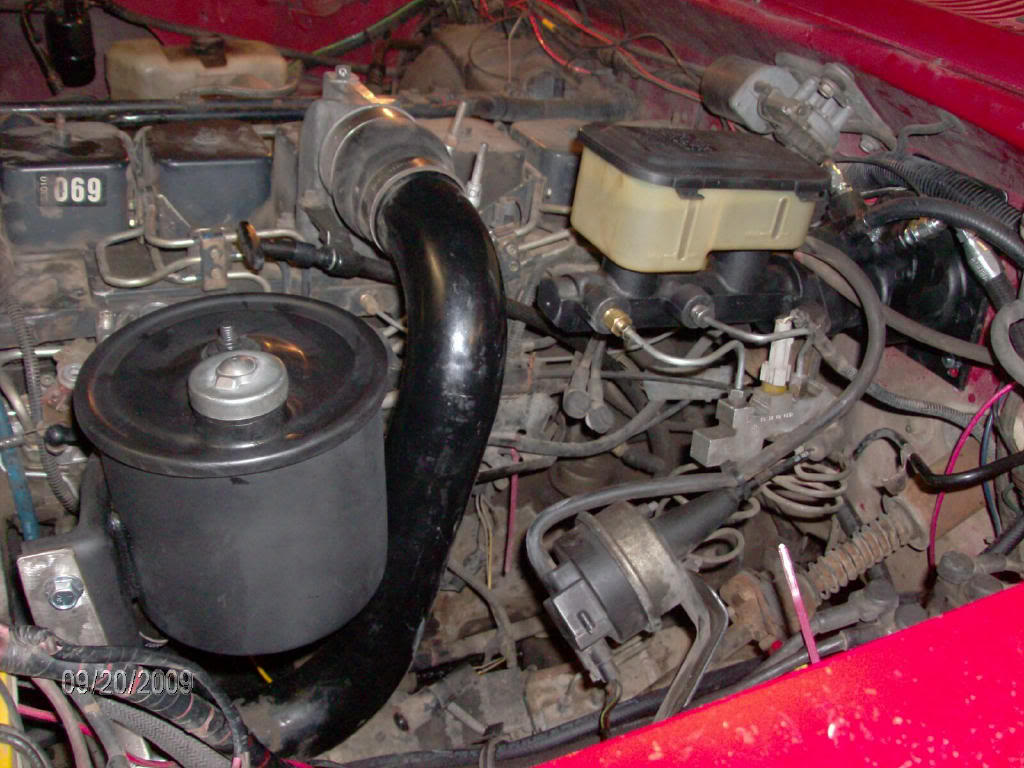
I read somewhere that a GM master cylinder would bolt right up to the brake lines. I must have ordered the wrong year because I had to fabricate one line. The rear most (closest to the firewall) line fit after a little bending to accomodate the different position of the master cylinder. The forward brake line fitting did not thread into the GM master cylinder, I used an adapter at the master cylinder and a piece of brake tubing 3/16 x 8", I used the Dodge fitting on the new line to attach to the proportioning valve.
With the expected pressure increase from the new pump I also installed a steering box input shaft seal kit. That was the easiest steering shaft seal I have ever done.
The steering effort at the steering wheel is effortless, very easy to turn, the brakes feel like a whole new system was installed not just a new booster. Update- The brakes are incredible, the pedal rides nice and high and only requires 1/2 to 3/4 of an inch to lock the front brakes, this is way better than I expected. This hydro boost unit did not work this well in the truck I took it off of, so the ZF pump must be what's making the difference.
I have an electric vacuum pump from a PowerStroke still to install.
Now I need a case of engine degreaser and a handfull of quarters.
The fitting at the 10 oclock position on the hydro boost is the pressure in line, it connects to the output on the pump. There is a 6AN to O ring adapter needed for the hydro boost end. With a 8AN to 6AN adapter at the pump.
The fitting at the 2 oclock position on the hydro boost is the pressure output to the steering box. both the hydro boost and the steering box use a 6AN to O ring adapter.
The remaining hose barb port on the hydro boost is the return line. I used a T fitting to connect the return line from the hydro boost and the return line from the steering box, I used the stock steel return line with a new piece of hose, I fed the output from the T to the power steering fluid cooler I mounted under the core support, behind my bumper. The cooler is not in direct air movement, but should do well enough with what it gets.
The output from the cooler then feeds into the fluid reservior. The reservior feeds the hydraulic pump through a 3/4 inch line. I made an L bracket and mounted it to the battery tray to hold the reservior. Here's the final product.
I read somewhere that a GM master cylinder would bolt right up to the brake lines. I must have ordered the wrong year because I had to fabricate one line. The rear most (closest to the firewall) line fit after a little bending to accomodate the different position of the master cylinder. The forward brake line fitting did not thread into the GM master cylinder, I used an adapter at the master cylinder and a piece of brake tubing 3/16 x 8", I used the Dodge fitting on the new line to attach to the proportioning valve.
With the expected pressure increase from the new pump I also installed a steering box input shaft seal kit. That was the easiest steering shaft seal I have ever done.
The steering effort at the steering wheel is effortless, very easy to turn, the brakes feel like a whole new system was installed not just a new booster. Update- The brakes are incredible, the pedal rides nice and high and only requires 1/2 to 3/4 of an inch to lock the front brakes, this is way better than I expected. This hydro boost unit did not work this well in the truck I took it off of, so the ZF pump must be what's making the difference.
I have an electric vacuum pump from a PowerStroke still to install.
Now I need a case of engine degreaser and a handfull of quarters.

Thread Starter
Registered User
Joined: Apr 2007
Posts: 249
Likes: 0
From: East of Denver
That pump and reservior came out of a Ford F600, it was used in a hydro boost system, more flow and pressure than the stock Saginaw style pumps.
Thread Starter
Registered User
Joined: Apr 2007
Posts: 249
Likes: 0
From: East of Denver
Trending Topics


Thread Starter
Registered User
Joined: Apr 2007
Posts: 249
Likes: 0
From: East of Denver

Registered User
Joined: Mar 2008
Posts: 344
Likes: 0
From: North Haven,CT "Living in occupied teritory" & Barton,VT
GREAT POST!!! What year F600 and what year GM hydro boost did you get. Also where did you get the ZF pump set up and for how much. My truck doesn't have cruse or air and all I do is tow so this is a must for me.
Thread Starter
Registered User
Joined: Apr 2007
Posts: 249
Likes: 0
From: East of Denver
You can also use a GM steering pump from a hydro boost system, it will fit the Cummins adapter and I believe the pressure is set a little higher.
Thread Starter
Registered User
Joined: Apr 2007
Posts: 249
Likes: 0
From: East of Denver
Update
I found the other day that my brakes have been dragging. My best guess was that the small cooler I used was causing a restriction in the return system. I installed a larger cooler and a lot of the problem went away.
Since these ZF pumps move so much fluid the 3/8 line return is not enough. My external reservior has a 1/2 inch return inlet that I reduced to 3/8. I am going to replumb the return system from the T joining the return from the hydro boost and the return from the PS box in 1/2 inch cooler and line, I suspect this will solve the problem.
When I start the truck the brake pedal moves down a little bit on it's own, putting a small load on the master cylinder causing the brakes to drag. It is easy to pull the brake pedal back up by hand so I installed a clutch return spring between the dash inner structure and the brake pedal, this has solved the problem for now. When I finish the rework I will post results, but I think it will not require the additional spring.
Since these ZF pumps move so much fluid the 3/8 line return is not enough. My external reservior has a 1/2 inch return inlet that I reduced to 3/8. I am going to replumb the return system from the T joining the return from the hydro boost and the return from the PS box in 1/2 inch cooler and line, I suspect this will solve the problem.
When I start the truck the brake pedal moves down a little bit on it's own, putting a small load on the master cylinder causing the brakes to drag. It is easy to pull the brake pedal back up by hand so I installed a clutch return spring between the dash inner structure and the brake pedal, this has solved the problem for now. When I finish the rework I will post results, but I think it will not require the additional spring.

Thread Starter
Registered User
Joined: Apr 2007
Posts: 249
Likes: 0
From: East of Denver
Update
After running this sytem for a while, if you use the big ZF pump, you must ensure that there is enough return flow capability. I used 3/8 line from the T where the 2 return lines (hydro boost & steering box) connected to the reservior, I had to make a new T with a 1/2 inch return line. When cold the brakes would apply themselves (trashed rotors and drums) and the over pressure blew the seals in my hydro boost unit.
The self applying brakes was cool for morning warm ups, untill I let it run too long and it rolled down the drive way.
The self applying brakes was cool for morning warm ups, untill I let it run too long and it rolled down the drive way.