
VE rebuild with pics Look inside


Registered User
Joined: Mar 2006
Posts: 104
Likes: 0
Pump Guru's I need your help !
Thank God and Greyhound I finally found this. In the middle of a seal job and memory not what it used to be, pics and info a lifesaver. Could not afford to take it to the pump shop to fix a leak. BIG BIG HELP - - THANK YOU R C
Adminstrator-ess

Joined: Mar 2003
Posts: 22,594
Likes: 19
From: New Holland, PA
Once you put up the next section of the rebuild I'll weed out all these posts. It's a lot easier to follow a "How To" thread if there aren't a bunch of "attaboy" posts in the middle of it - not that you don't deserve them.


Thread Starter
Registered User
Joined: Dec 2006
Posts: 1,269
Likes: 0
From: Jonesboro, TEXAS
Well Lets look at some Mods while were in here.
Note I am in no way responsible if you do this and burn things up or get a ticket for excessive acceleration
Lets start with fuel pins
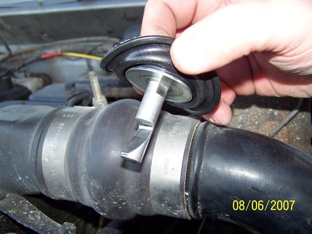
Fuel pins do the same job as a cam plate on a P-7100 pump. They change how much fuel is delivered in relation ship with boost. As boost builds it pushes down on the diaphragm and pushes the pin down allowing more fuel. There is a spring under it that holds it up and is adjustable and can be set to speed up or slow down the fuel rate in relation to boost. turning the star wheel at the base clock wise will put less pressure on the spring allowing the fuel rate to increase at lower boost = more smoke at lower boost, Counter-clockwise will put more pressure on the spring and slowes the fuel rate at lower boost levels = less smoke at lower boost.
this is the small pin that rides on the fuel pin. It comes out from the front of the pump
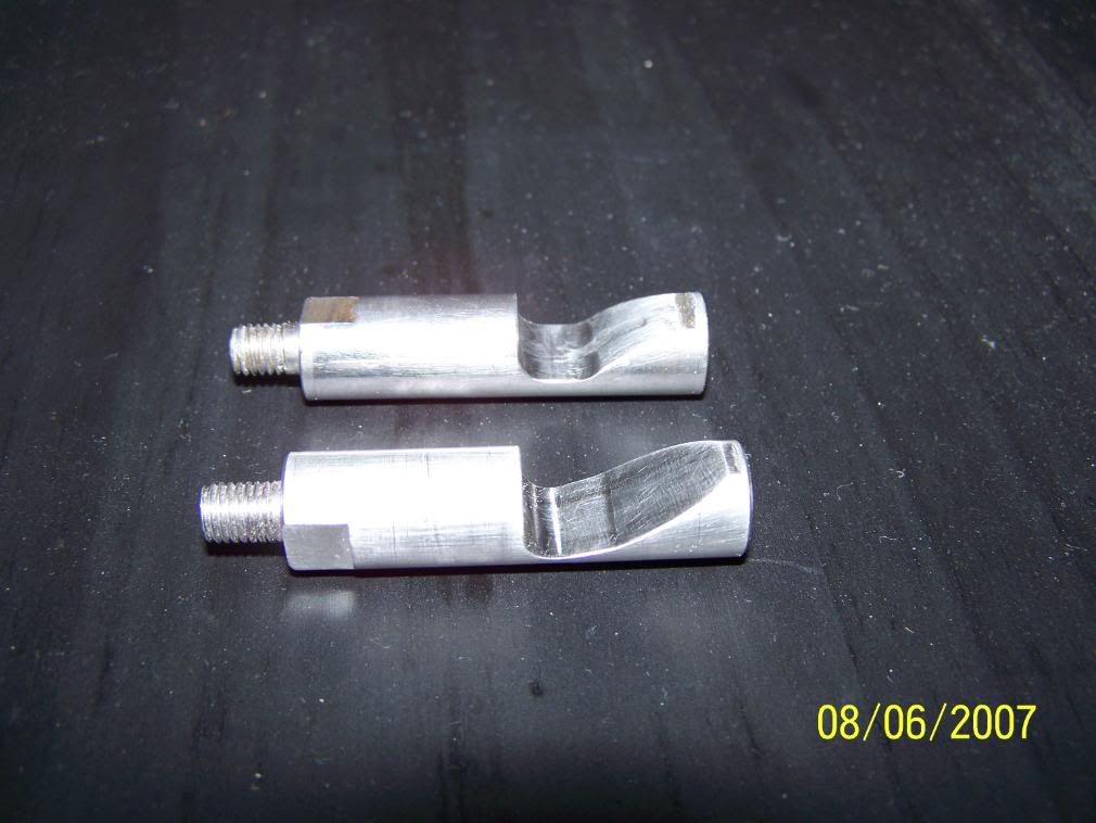
the one on the left is a Bully Dog, center is stock, right is Denny T.
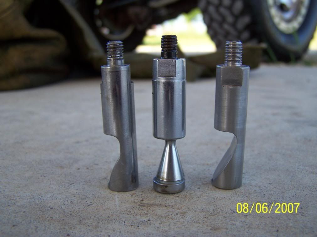
The stock one can bee turned were the eccentric cone is to the rear of the motor thus allowing the pin that rides on it to extend farther out and give more fuel. This is free and will give a noticeable bump in power.
The one on top is a Bully Dog the other is a Denny T. I ran both in my truck and found (like many others) that the Bully Dog made good power but was way to soft and gouged and would stick. The Denny T is maid from very hard SS and will just polish the area and is a lot cheaper. The Denny T pin gives a real boost in power over the Bully Dog and has held up great. DO NOT try to go cheep and make one from mild steel it wont last 100 miles if that . There are others out there but I have not tryed them my self.
On the top cover (silver price on top of this pump) there is a Torx head screw that sets the starting depth of the fuel pin at 0psi boost. Ofter called the "Smoke Screw". It can be set deeper CW to give better take off power be for boost comes up but also creates more smoke. It can also be set for less low-no boost fuel and less smoke for pulling and or to compensate for large injectors to keep smoke under control.
Note I am in no way responsible if you do this and burn things up or get a ticket for excessive acceleration
Lets start with fuel pins
Fuel pins do the same job as a cam plate on a P-7100 pump. They change how much fuel is delivered in relation ship with boost. As boost builds it pushes down on the diaphragm and pushes the pin down allowing more fuel. There is a spring under it that holds it up and is adjustable and can be set to speed up or slow down the fuel rate in relation to boost. turning the star wheel at the base clock wise will put less pressure on the spring allowing the fuel rate to increase at lower boost = more smoke at lower boost, Counter-clockwise will put more pressure on the spring and slowes the fuel rate at lower boost levels = less smoke at lower boost.
this is the small pin that rides on the fuel pin. It comes out from the front of the pump
the one on the left is a Bully Dog, center is stock, right is Denny T.
The stock one can bee turned were the eccentric cone is to the rear of the motor thus allowing the pin that rides on it to extend farther out and give more fuel. This is free and will give a noticeable bump in power.
The one on top is a Bully Dog the other is a Denny T. I ran both in my truck and found (like many others) that the Bully Dog made good power but was way to soft and gouged and would stick. The Denny T is maid from very hard SS and will just polish the area and is a lot cheaper. The Denny T pin gives a real boost in power over the Bully Dog and has held up great. DO NOT try to go cheep and make one from mild steel it wont last 100 miles if that
. There are others out there but I have not tryed them my self.On the top cover (silver price on top of this pump) there is a Torx head screw that sets the starting depth of the fuel pin at 0psi boost. Ofter called the "Smoke Screw". It can be set deeper CW to give better take off power be for boost comes up but also creates more smoke. It can also be set for less low-no boost fuel and less smoke for pulling and or to compensate for large injectors to keep smoke under control.
Thread Starter
Registered User
Joined: Dec 2006
Posts: 1,269
Likes: 0
From: Jonesboro, TEXAS
GSK = 366 Spring = 3200 Governor spring kit
4200 Kit also available.
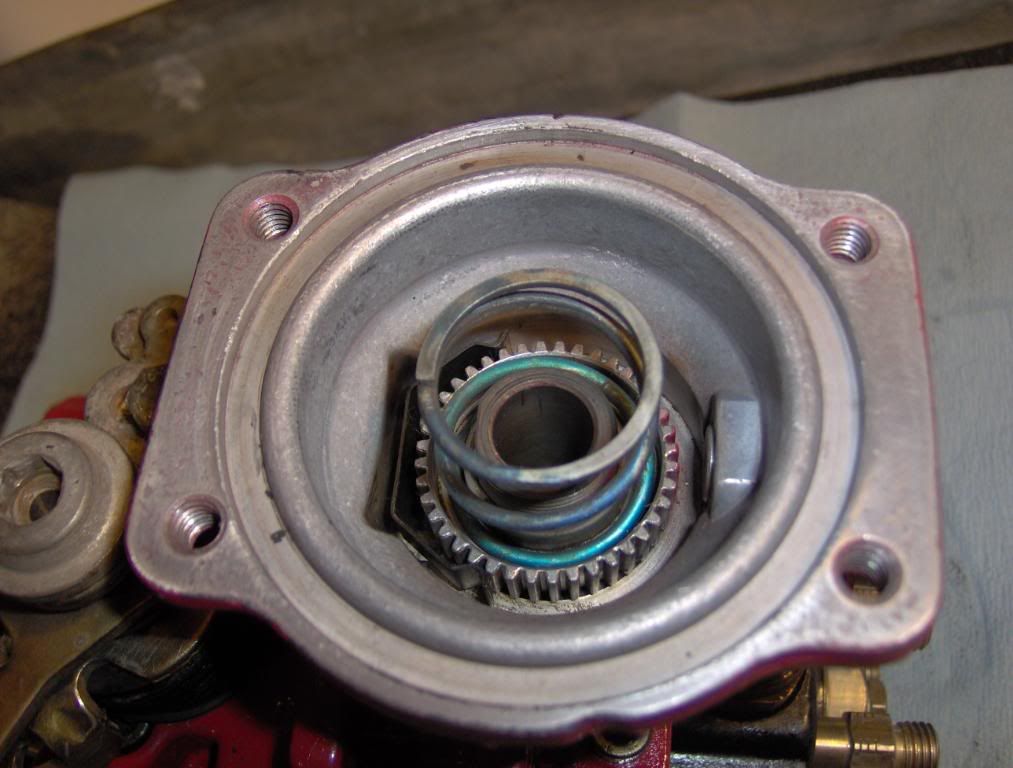
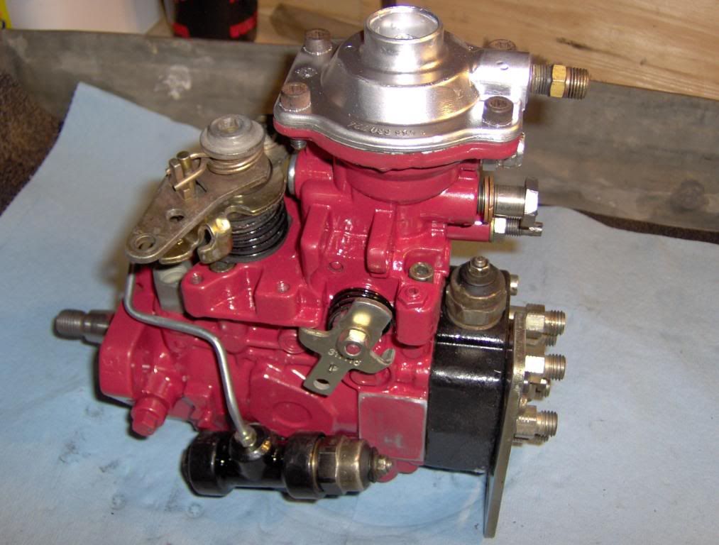
Starting with throttle linkage and springs removed ( shown how to earlyer) not required if not replacing the shaft seal
Remove the 4 Allen head bolts that holds the top to the main case.
Slowly lift the top from the pump, you may hear a clock as the lever comes off of the full fuel screw but that's fine. The spring and other parts will not fly out just go slow. as it comes up you will See the spring and can remove it form the throttle rod and hold it while you set the top aside.
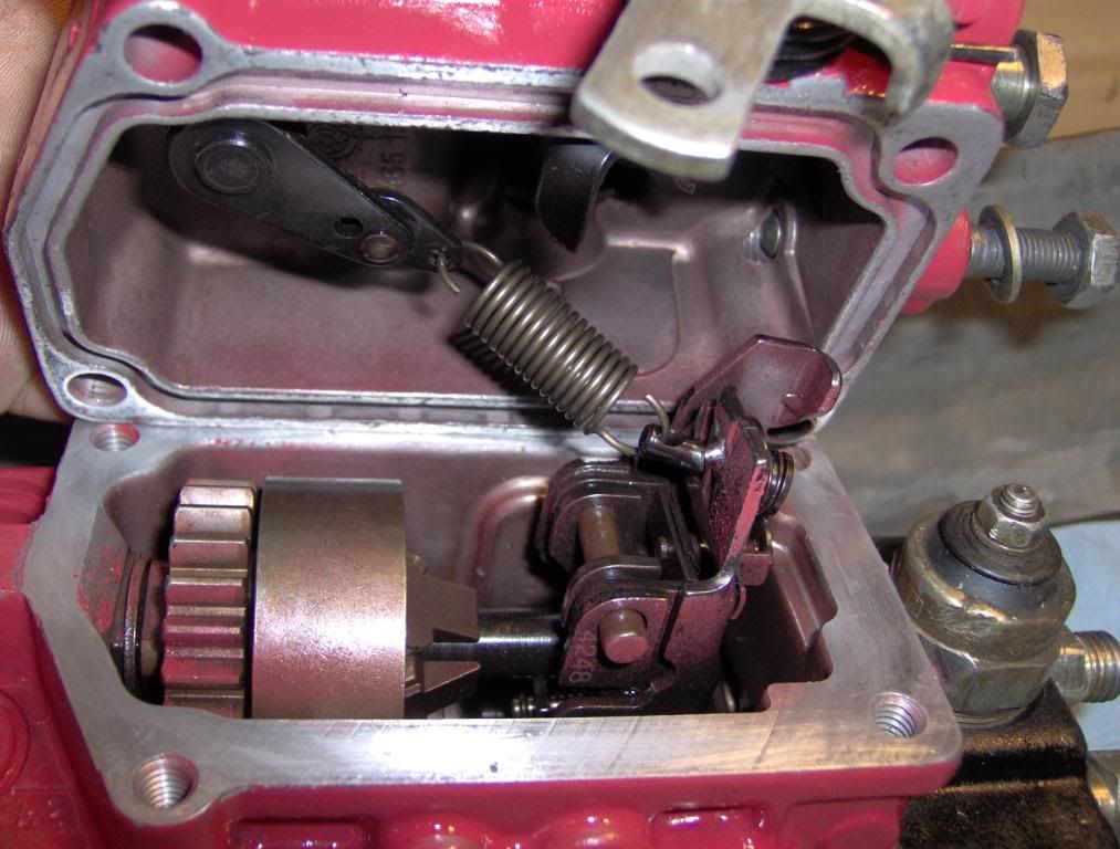
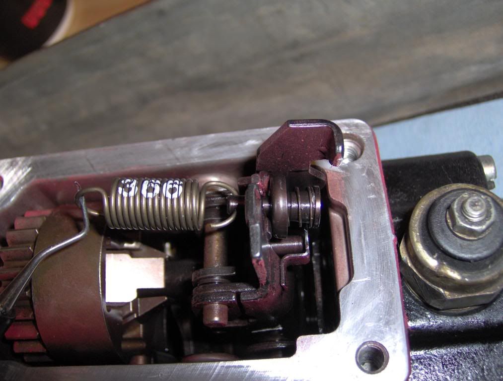
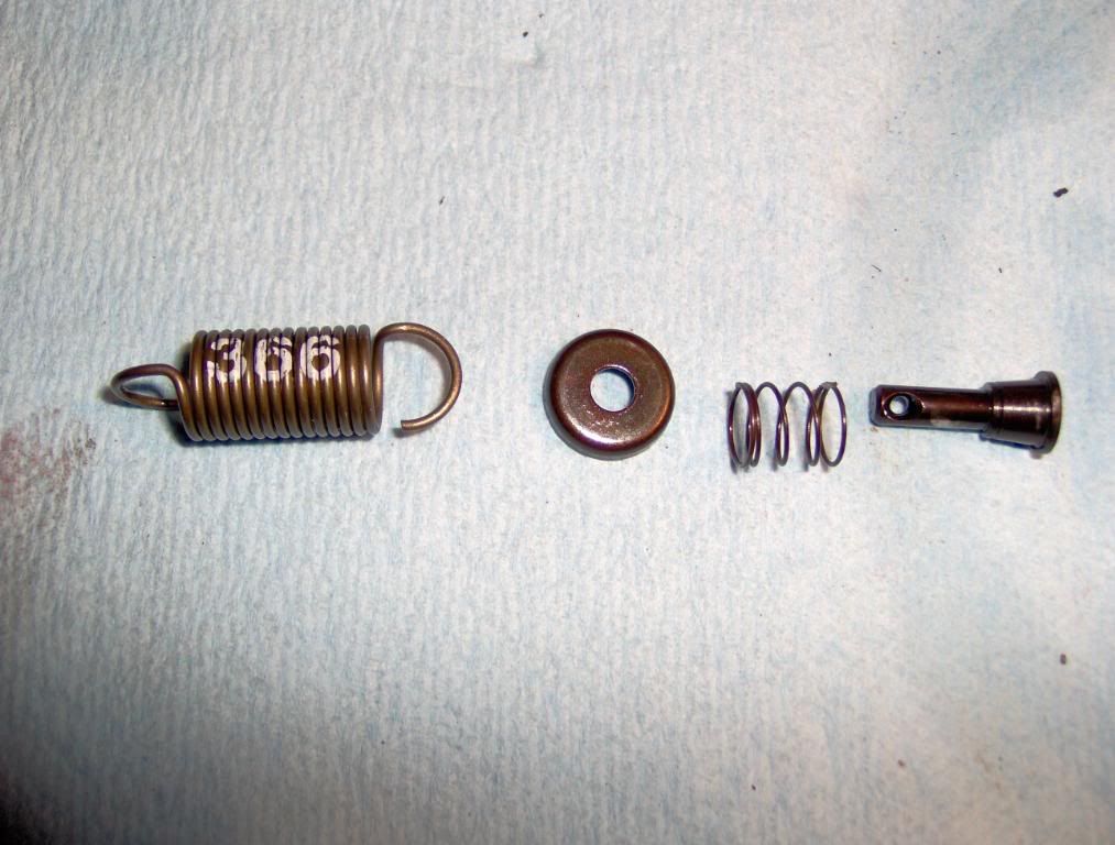
Then you can hold the "Top Hat" (pin with spring and washer that is connected to the other end of the gov spring) and remove the gov spring then the top hat.
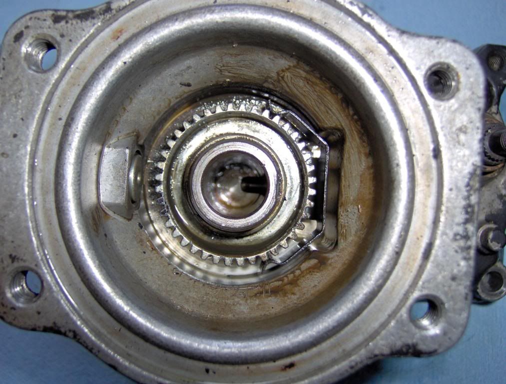
This is how all the parts go together. Make sure you have them all.
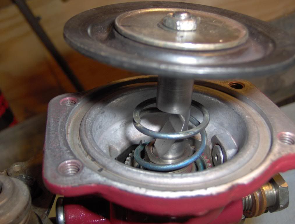
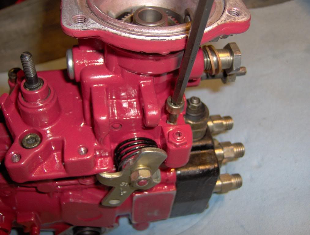
while you are here you can grind the AFC lever to alow more fuel just like the fuel pin. This is not reversable and should be left to guys that want all out performance!! You can not go back
The pin is pointed at the AFC lever and can be ground down to alow for more fuel. The more you grind the more fuel you get to a point. Do at your own risk. The other is the Kill lever DO NOT cut it.
Installing of the new spring is just reverse of removing the old one.
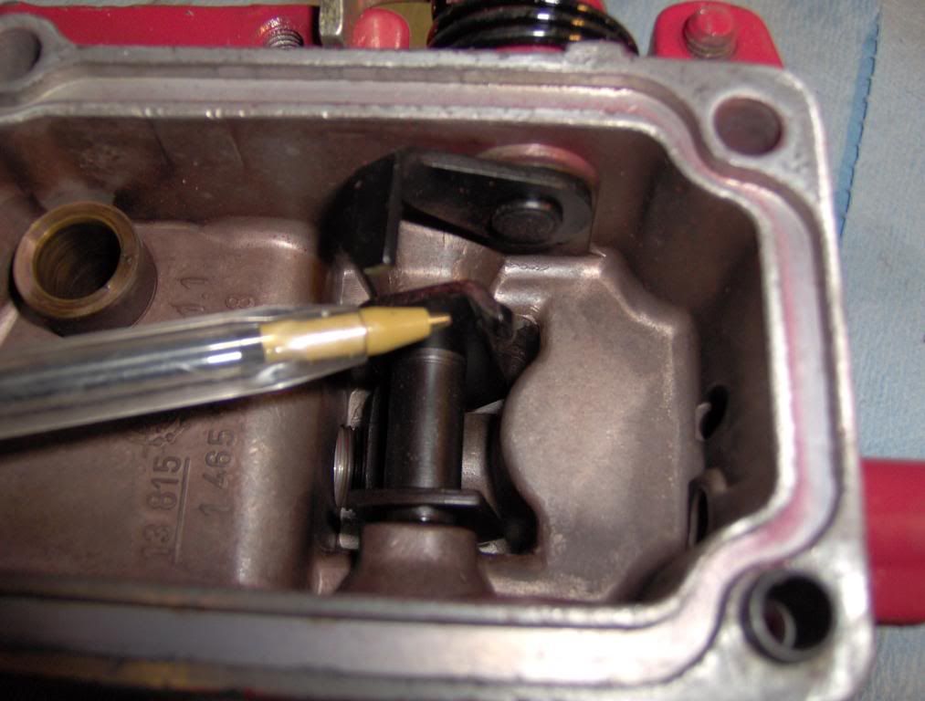
The lever behind the gov spring is the one that the Full fuel screw pushes on and can be pulled toward the front of the pump with a small wire or string to clear the screw as the top is placed back on the pump if the screw was left in place. As you set the top on you can then remove the string or wire and finish installing the top. One other way is to note the depth of the full fuel screw and back it out till the tip is flush with the inside of the cover, as you cam see , this will alow the cover to set on the pump with no probs and then it can be placed back to the previously noted depth.
When you have it all back together remove the intake tube from the turbo and have a bord or some thing solid that you can place over the intake of the turbo to cut off the air and kill the motor incase of runaway.
DO NOT USE YOUR HAND
4200 Kit also available.
Starting with throttle linkage and springs removed ( shown how to earlyer) not required if not replacing the shaft seal
Remove the 4 Allen head bolts that holds the top to the main case.
Slowly lift the top from the pump, you may hear a clock as the lever comes off of the full fuel screw but that's fine. The spring and other parts will not fly out just go slow. as it comes up you will See the spring and can remove it form the throttle rod and hold it while you set the top aside.
Then you can hold the "Top Hat" (pin with spring and washer that is connected to the other end of the gov spring) and remove the gov spring then the top hat.
This is how all the parts go together. Make sure you have them all.
while you are here you can grind the AFC lever to alow more fuel just like the fuel pin. This is not reversable and should be left to guys that want all out performance!! You can not go back
The pin is pointed at the AFC lever and can be ground down to alow for more fuel. The more you grind the more fuel you get to a point. Do at your own risk. The other is the Kill lever DO NOT cut it.
Installing of the new spring is just reverse of removing the old one.
The lever behind the gov spring is the one that the Full fuel screw pushes on and can be pulled toward the front of the pump with a small wire or string to clear the screw as the top is placed back on the pump if the screw was left in place. As you set the top on you can then remove the string or wire and finish installing the top. One other way is to note the depth of the full fuel screw and back it out till the tip is flush with the inside of the cover, as you cam see , this will alow the cover to set on the pump with no probs and then it can be placed back to the previously noted depth.
When you have it all back together remove the intake tube from the turbo and have a bord or some thing solid that you can place over the intake of the turbo to cut off the air and kill the motor incase of runaway.
DO NOT USE YOUR HAND

Registered User
Joined: Nov 2007
Posts: 335
Likes: 0
great job just one thing, if you would like my two cents worth
instead of hooking the top hat and 366 spring to saft like you did just pull the throtle saft out of the pump top and hook it up, much easyer and way faster and you dont need a thrid arm to do it, lol
instead of hooking the top hat and 366 spring to saft like you did just pull the throtle saft out of the pump top and hook it up, much easyer and way faster and you dont need a thrid arm to do it, lol
Thread Starter
Registered User
Joined: Dec 2006
Posts: 1,269
Likes: 0
From: Jonesboro, TEXAS
Now for the Full Fuel screw
This will really wake things up.
Befor you start remove the intake tube from the turbo and get some thing hard and flat that can be used to cut off the air and kill the motor in case of runaway.
DO NOT use your hand it WILL get pulled into the turbo
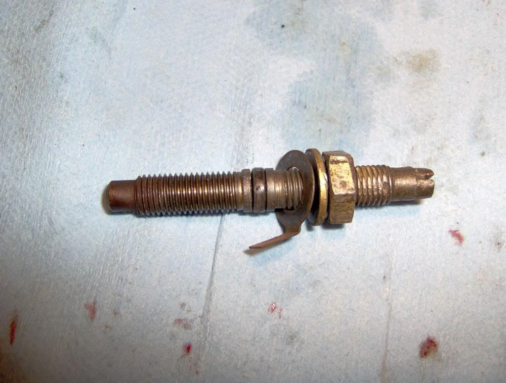
The one I am talking about is the one on the rear of the pump nearest to the shut down solenoid. If your pump has never been messed with it will have a small collar that is tack welded to the screw and will need to be removed to alow for moor adjustment. You can mark the stock depth of the screw and remove it and then remove the collar and reinstall it to the stock depth.
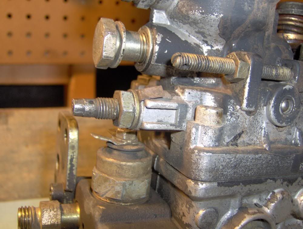
Here is the screw with the collar removed
Most guys will go 2 turns clockwise from stock and are very happy. If you want to get all you can out of your pump I start the truck with it in the stock position. Then using a 6mm socket and ( or flat tip screwdriver) a extension slowly turn it CW. Go about 1/4 turn at a time after 2 turns and rev the engine a few 100 RPM and then release it fast and make sure that it idles down as fast as it use to. Repeat this till you get to the point were it is slow to idle back down or the RPM's hover or stick. Now you are close to runaway so back off till it idles down like it should ( about 1/4-1/2 turn) and lock the jam nut. Try it a few times and run it to WOT and make sure that it will idle back down as soon as you release the throttle.
Your throttle will be a few 100 RPM higher than stock when done. You need to get to the low idle screw and loosen the jam nut and turn it counter clock wise to get it back to about stock RPM then tighten the jam nut.
This will really wake things up.
Befor you start remove the intake tube from the turbo and get some thing hard and flat that can be used to cut off the air and kill the motor in case of runaway.
DO NOT use your hand it WILL get pulled into the turbo
The one I am talking about is the one on the rear of the pump nearest to the shut down solenoid. If your pump has never been messed with it will have a small collar that is tack welded to the screw and will need to be removed to alow for moor adjustment. You can mark the stock depth of the screw and remove it and then remove the collar and reinstall it to the stock depth.
Here is the screw with the collar removed
Most guys will go 2 turns clockwise from stock and are very happy. If you want to get all you can out of your pump I start the truck with it in the stock position. Then using a 6mm socket and ( or flat tip screwdriver) a extension slowly turn it CW. Go about 1/4 turn at a time after 2 turns and rev the engine a few 100 RPM and then release it fast and make sure that it idles down as fast as it use to. Repeat this till you get to the point were it is slow to idle back down or the RPM's hover or stick. Now you are close to runaway so back off till it idles down like it should ( about 1/4-1/2 turn) and lock the jam nut. Try it a few times and run it to WOT and make sure that it will idle back down as soon as you release the throttle.
Your throttle will be a few 100 RPM higher than stock when done. You need to get to the low idle screw and loosen the jam nut and turn it counter clock wise to get it back to about stock RPM then tighten the jam nut.

Registered User


Joined: Oct 2005
Posts: 6,457
Likes: 95
From: KENTUCKY
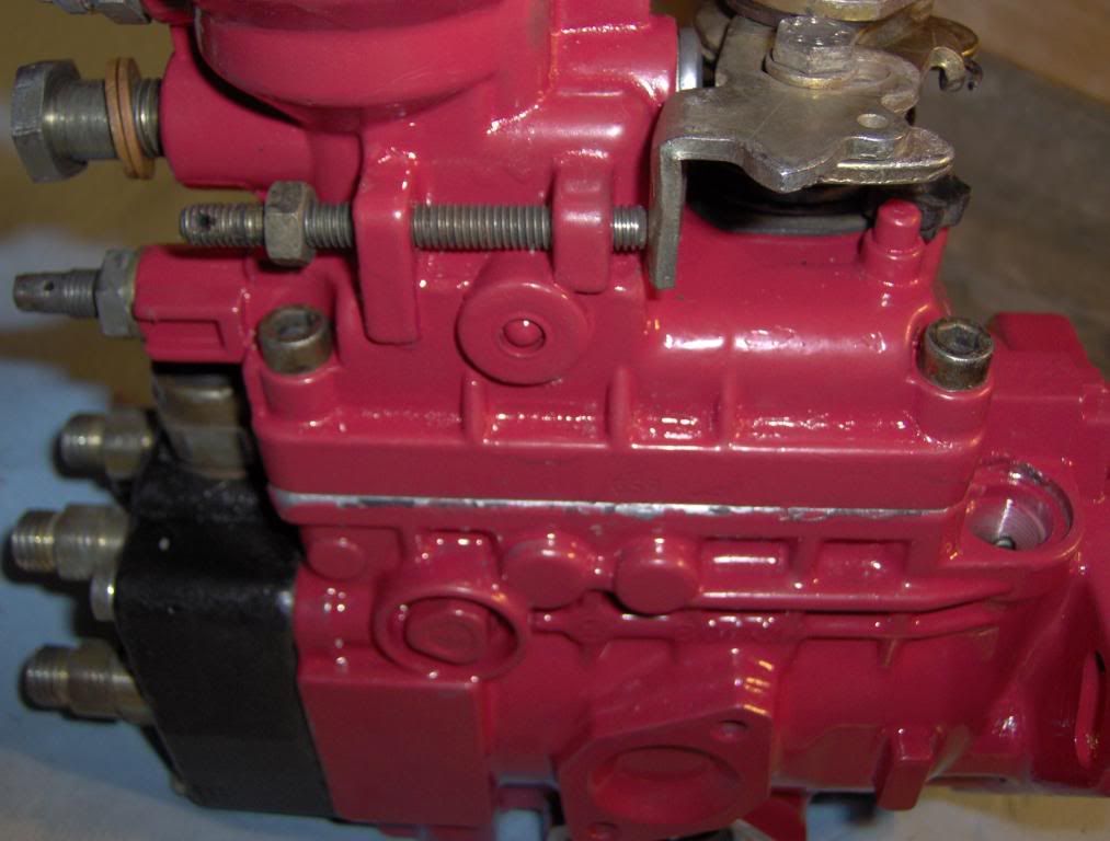
Just about every fuel-screw I see has flattened/marred threads like this one :
I went through my million-piece metric tap and die set and could not find a die of the correct size/thread to clean up the threads prior to re-assembly.
If memory serves me, an 8 x 1.25 was the correct diameter, but the wrong thread-pitch, which I believe was 1.00-pitch, instead of 1.25.
Can anyone confirm the size/pitch of the fuel-screw ??
Thanks.
By the way, this is the most detailed VE pictorial yet.
Your thorough explanations and plenty of pictures should give even a beginner the understanding and confidence to re-seal a leaky pump.

Registered User
Joined: Jun 2008
Posts: 4
Likes: 0
In the first pic of the pump apart [ in the top left of the pic there is a tubing thing with the square banjo and the regulating valve [ with the crazy two sided 10mm ] I think my ugly leak is from there --- yesteday i got new orings and a modded copper washer under the banjo......still leaks.. does some know how to fix this... Thnx for any suggestions... making the road slippery one drive at a time
Registered User
Joined: Oct 2005
Posts: 6,457
Likes: 95
From: KENTUCKY
In the first pic of the pump apart [ in the top left of the pic there is a tubing thing with the square banjo and the regulating valve [ with the crazy two sided 10mm ] I think my ugly leak is from there --- yesteday i got new orings and a modded copper washer under the banjo......still leaks.. does some know how to fix this... Thnx for any suggestions... making the road slippery one drive at a time
I think THIS is what you are referring to :
https://www.dieseltruckresource.com/...15&postcount=9
That is called a control-valve.
If replacing the four O-rings doesn't fix it, there could be a crack in the tiny tube.
Registered User
Joined: Jun 2008
Posts: 4
Likes: 0
Thnx Bear Killer ---- the tubing is not leaking..... My problem seems to be finding the EXACT size o-rings and not able to get it tight enough because the crazy two flat sided bolt head.... thank thank you again for the thread
10mm crows foot and oring part numbers
10mm crows foot and oring part numbers