
The motor Build thread.


Registered User
Joined: Feb 2010
Posts: 1,635
Likes: 59
From: New York
Very nice, with the pistons coming up .010 on the block, does the head gasket make up for it? If not wouldn't that interfere with the head?
The cross hatching was well done, hard to find anyone around here that can machine that good
The cross hatching was well done, hard to find anyone around here that can machine that good
Thread Starter
Registered User
Joined: Oct 2008
Posts: 1,591
Likes: 11
From: Thunder Bay
Yes the thicker head gasket makes up for it so it is all good. 0.024" piston protrusion should technically still be good because I think the crush thickness on the stock head gasket is still around 0.060" but since I'm running an aftermarket cam the concern is the pistons and the valves making contact. Technically speaking, I probably could have run a stock head gasket for what I have and what my tolerances are but this is the proper way of doing it
Sent from Tapatalk 4 via a Galaxy S3
Sent from Tapatalk 4 via a Galaxy S3
Thread Starter
Registered User
Joined: Oct 2008
Posts: 1,591
Likes: 11
From: Thunder Bay
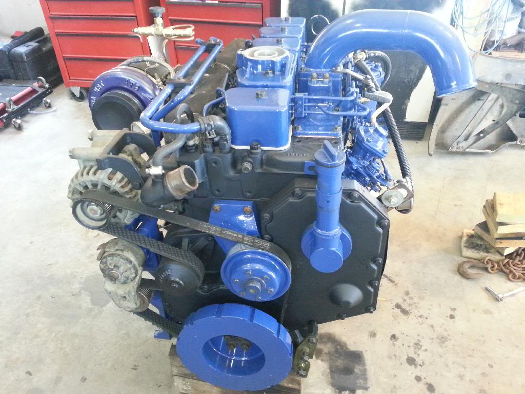
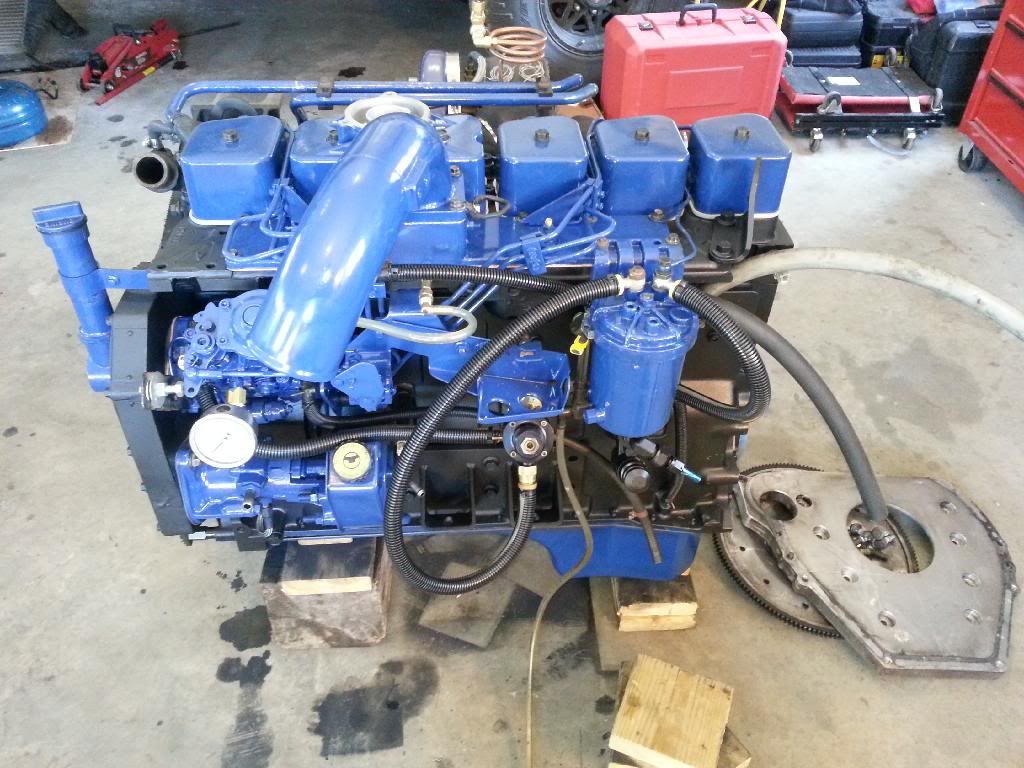
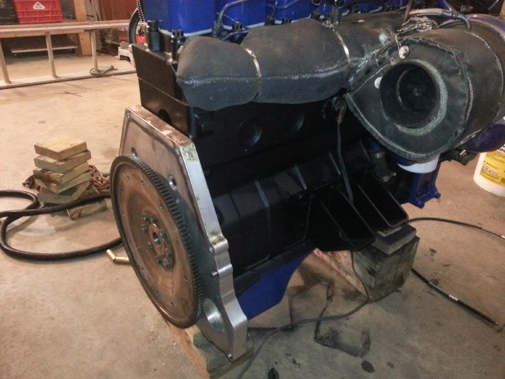
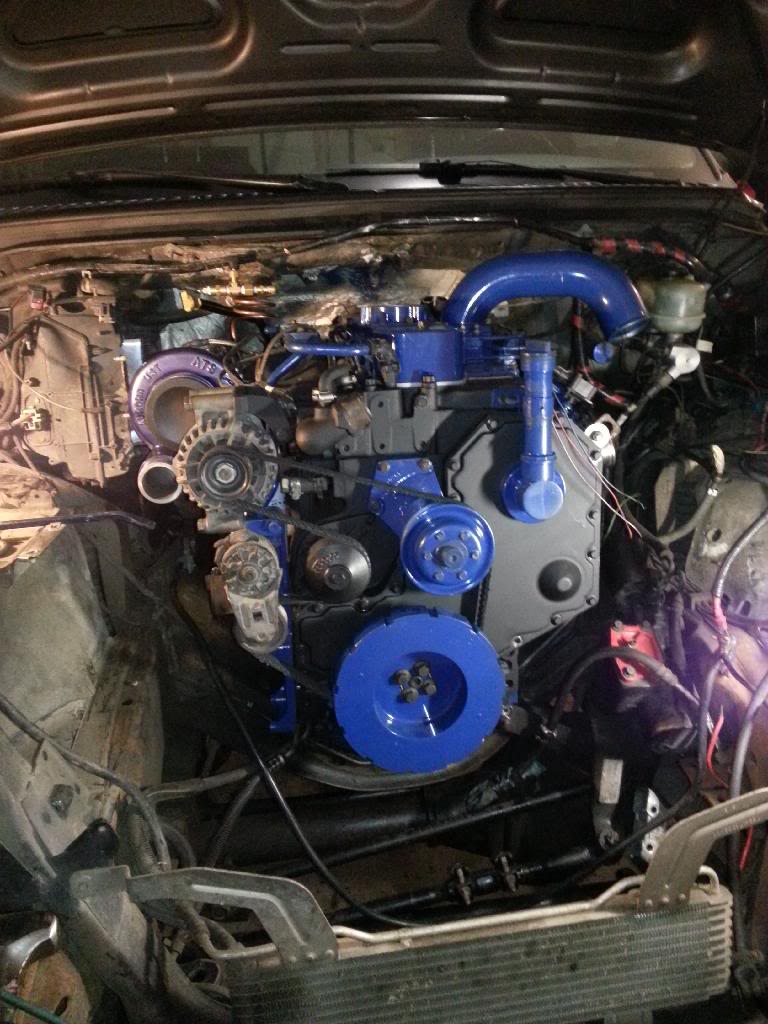
Last night I did some more work. Did the fuel lines and whatnot on that side of the motor and installed the manifold and turbo and blankets and everything on the other. I also got the fuel return line in and stuff. Motor is nearly buttoned up. Just need to finish the IP return with a different hose so it won't leak, finish the valet switch and the TPS wiring (which really doesn't need to be done until the motor is in the truck)
I also spent a significant amount of time last night cleaning the garage, cleaning tools and putting them away after I had terrorized it for the last week...
Tonight I was just figuring the logistics and mounting of a couple items. Namely the TPS and my valet. I also spent some time trying to figure out what the hell I had done and where I left off for my wiring from 2 months ago. That took a good while. I had installed a switch for the KSB, valet, FSS, pusher pump, grid relays and maybe one or 2 other things along with some wiring for the transmission controller and I apparently forgot to label a few wires so I'm still not entirely sure what they are for exactly... lesson learned, next time I won't stop and forget about a wiring job for 2 months... it was almost done too... oh well. Not that big of a deal. I also dropped the tank and figured out how I'm going to mount/route the stuff for the pusher pump. No pics of that yet, not until I get it in place. Tomorrow I need to stop at the local parts place to get a bunch of fittings for the fuel system and 2 fittings for the valet as well.
Update pics from Last night. Ain't she purdy?

Registered User


Joined: Apr 2002
Posts: 1,602
Likes: 93
From: Richmond, VA
It's looking sweet!
Thanks for the response on the cooling nozzles (I have two that I found in the pan of the truck I am currently running when i dropped it to fix the thrust bearing that had fallen off.) Apparently the black ones can work their way out when they get too hot. Hopefully the green are better.
Thanks for the response on the cooling nozzles (I have two that I found in the pan of the truck I am currently running when i dropped it to fix the thrust bearing that had fallen off.) Apparently the black ones can work their way out when they get too hot. Hopefully the green are better.
Registered User
Joined: Jul 2010
Posts: 181
Likes: 0
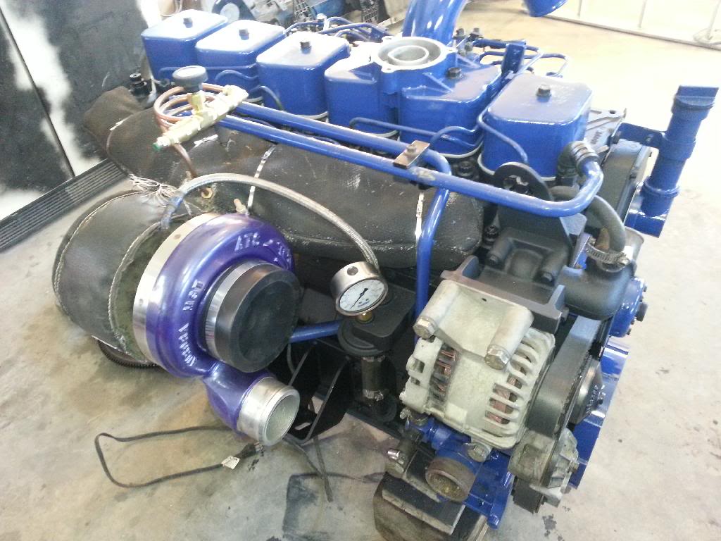
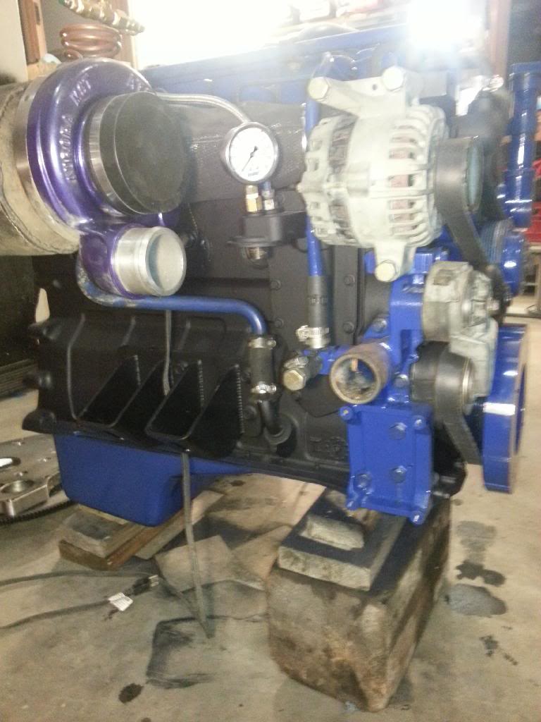
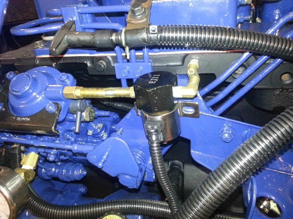
may i ask what is the copper tube coming out of the manifold and are them guages on top of the oil filter housing and off the injection pump?
lookin really good wish i would have spent that kind of time on mine when i did my swap paint it all flat black then shove it in.
lookin really good wish i would have spent that kind of time on mine when i did my swap paint it all flat black then shove it in.
Thread Starter
Registered User
Joined: Oct 2008
Posts: 1,591
Likes: 11
From: Thunder Bay
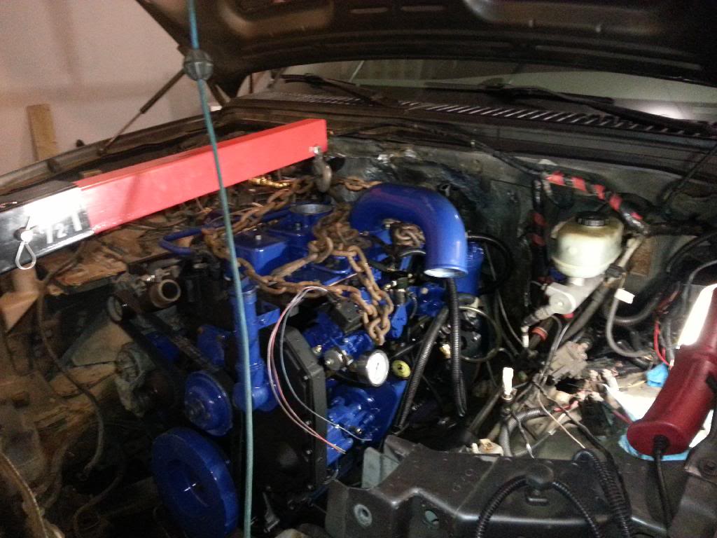
the copper tube is for a drive pressure gauge. I originally installed it to monitor my drive pressure and see if I could figure out why I was getting so much surging. I did figure it out. I apparently have the opposite problem of everyone else. My boost is consistently several PSI higher than my drive pressure. At no point whatsoever is my drive pressure higher than boost. The pressure difference causes turbo surge.
And yes, one goes to the oil to monitor oil pressure (100psi gauge) and the other is to the IP to monitor case pressure (200psi gauge)
And yes, one goes to the oil to monitor oil pressure (100psi gauge) and the other is to the IP to monitor case pressure (200psi gauge)
Thread Starter
Registered User
Joined: Oct 2008
Posts: 1,591
Likes: 11
From: Thunder Bay
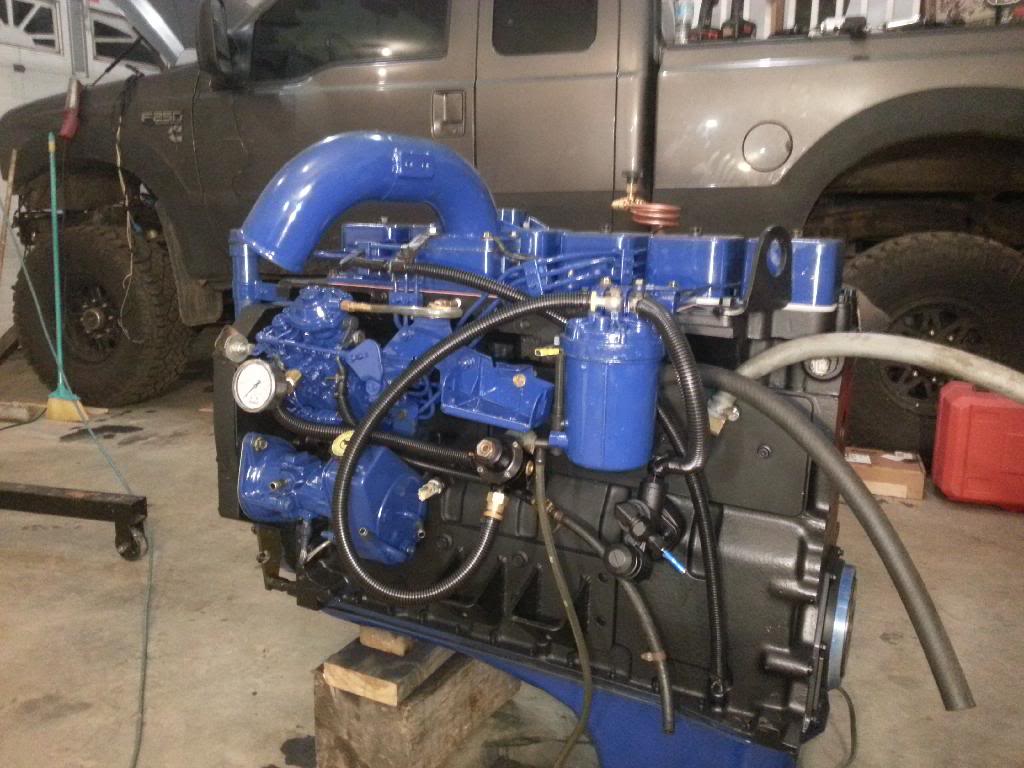
Last night's progress pics.
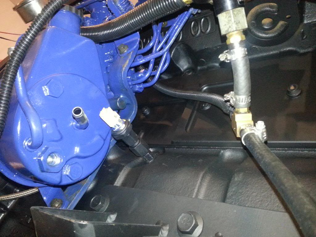
First order of business was getting the Valet set up. I had to go buy some fittings during the day to finish this and mount it. Also had to get fittings for the pusher pump.
Second was getting the fuel return from the IP set up properly... I needed to buy some hose and fittings for that and get it routed in behind and out of the way, then T-ed in with the regulator return.
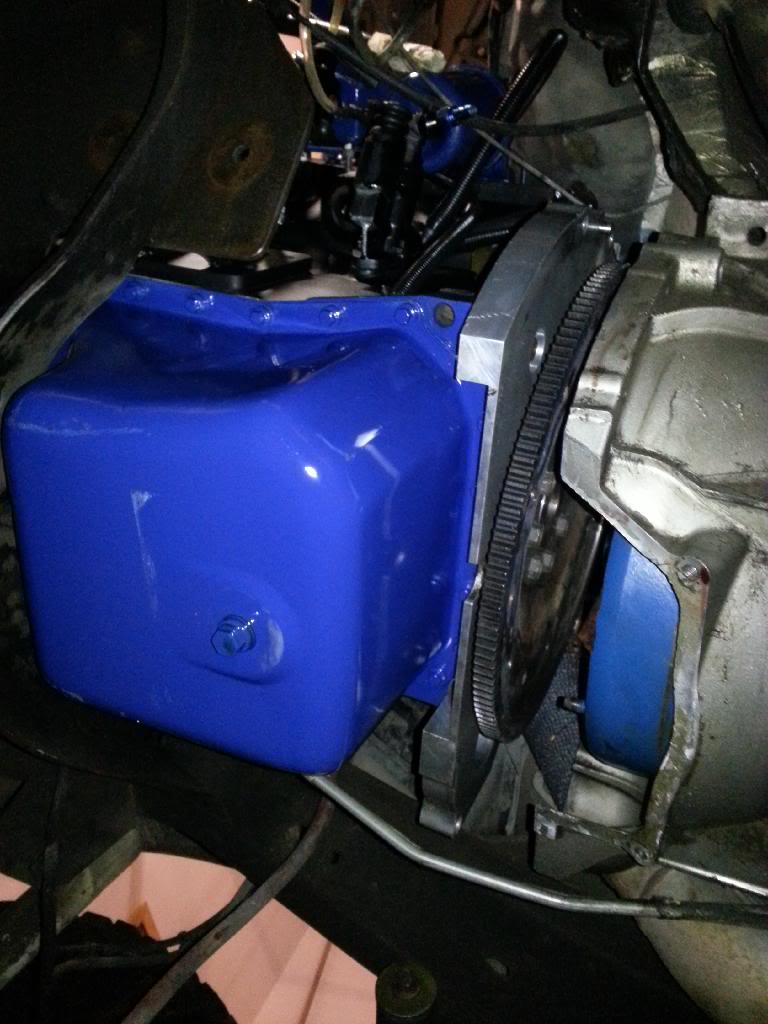
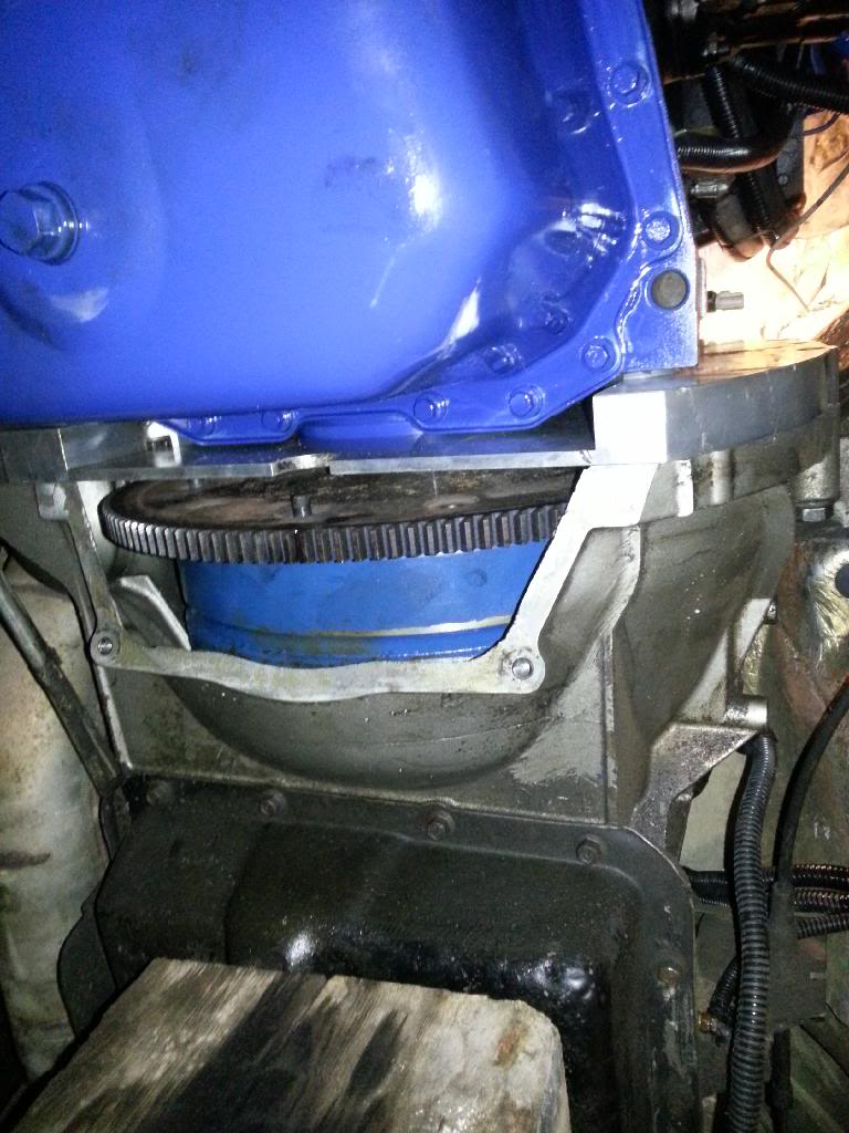
Next was getting the adapter plate and flex plate on. It's a destroked unit. The flex plate is pretty beefy too.
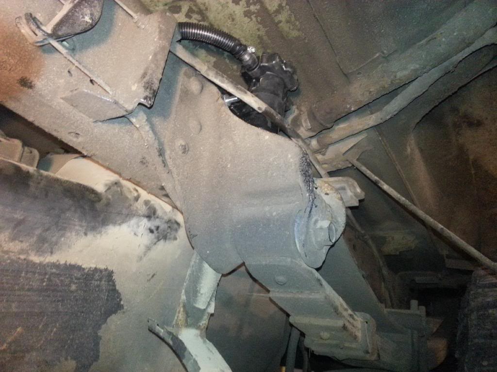
Last on the list was mounting the pusher and getting the fuel lines hooked up. The wiring is all installed in the cab, through the firewall already. All I need to do for the wiring is loom it and run it down the frame rail then connect the wires with some butt connectors and weather proof shrink tube. That's for another day. Today is a day off from the truck.
I would also like to point out that the mounting of the pusher was the biggest PITA of the entire job thus far. I was not impressed. I also didn't completely drop the tank which really limited how much room I had to work with. I cut the metal part of the fuel line on the sender with a dremel cut off disc (like 1" wide) attached to the remote dremel thingymabob. It's the only thing I could fit between the top of the tank and the box. On the other side of things I managed to cut the rubber hose off the metal line attached to the frame rail. Those were my 2 points I attached the hoses from. I mounted the pump right above the front spring bracket. It's nice and protected there and also really close to the tank.
I painted it all fancy like but I managed to pretty much ruin the paint job getting it in. That and the wd-40 I was using as lube for the drill makes it look even more like sh**. How'd my finger get in there!
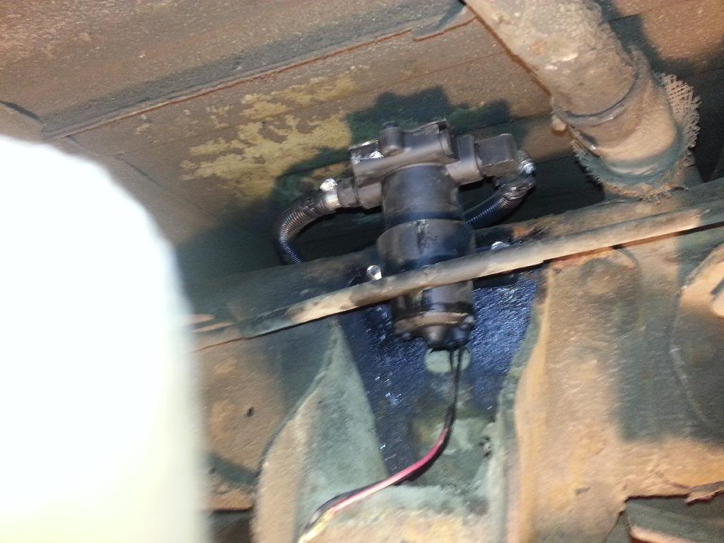
See, nice and protected
And the fuel lines...
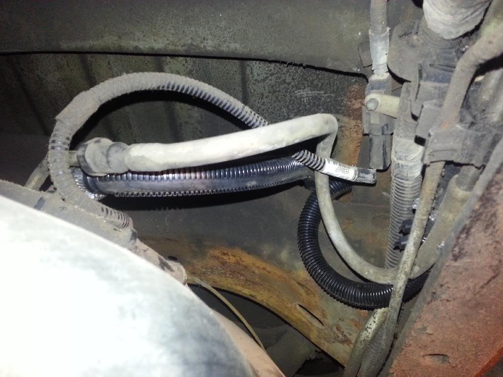
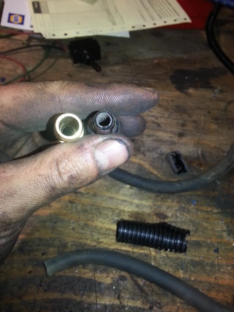
I also noticed this in the fuel system. To me this is an idiotic design oversight... even for a stock truck. Right out of the sender the metal line has the rubber line attached to it, which goes to the steel line on the frame rail. Not only is the rubber supply line only 1/4" but it has a 1/4" hose barb in there too, which essentially necks down the supply line right out of the sender to MAYBE 3/16", but realistically maybe only 5/32". Ridiculous. This pic shows the 1/4" thick plastic hose barb next to my brass 3/8" hose barb. The picture really doesn't do the size difference any justice...
After that I called it a night, it was pushing midnight last night by the time I got in the house from the garage anyway...
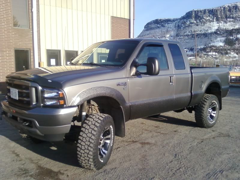
For those that haven't seen it yet. This is an older picture of my truck. It looks the same, save different wheels and tires... and it's more dirty right now...
First order of business was getting the Valet set up. I had to go buy some fittings during the day to finish this and mount it. Also had to get fittings for the pusher pump.
Second was getting the fuel return from the IP set up properly... I needed to buy some hose and fittings for that and get it routed in behind and out of the way, then T-ed in with the regulator return.
Next was getting the adapter plate and flex plate on. It's a destroked unit. The flex plate is pretty beefy too.
Last on the list was mounting the pusher and getting the fuel lines hooked up. The wiring is all installed in the cab, through the firewall already. All I need to do for the wiring is loom it and run it down the frame rail then connect the wires with some butt connectors and weather proof shrink tube. That's for another day. Today is a day off from the truck.
I would also like to point out that the mounting of the pusher was the biggest PITA of the entire job thus far. I was not impressed. I also didn't completely drop the tank which really limited how much room I had to work with. I cut the metal part of the fuel line on the sender with a dremel cut off disc (like 1" wide) attached to the remote dremel thingymabob. It's the only thing I could fit between the top of the tank and the box. On the other side of things I managed to cut the rubber hose off the metal line attached to the frame rail. Those were my 2 points I attached the hoses from. I mounted the pump right above the front spring bracket. It's nice and protected there and also really close to the tank.
I painted it all fancy like but I managed to pretty much ruin the paint job getting it in. That and the wd-40 I was using as lube for the drill makes it look even more like sh**. How'd my finger get in there!
See, nice and protected
And the fuel lines...
I also noticed this in the fuel system. To me this is an idiotic design oversight... even for a stock truck. Right out of the sender the metal line has the rubber line attached to it, which goes to the steel line on the frame rail. Not only is the rubber supply line only 1/4" but it has a 1/4" hose barb in there too, which essentially necks down the supply line right out of the sender to MAYBE 3/16", but realistically maybe only 5/32". Ridiculous. This pic shows the 1/4" thick plastic hose barb next to my brass 3/8" hose barb. The picture really doesn't do the size difference any justice...
After that I called it a night, it was pushing midnight last night by the time I got in the house from the garage anyway...
For those that haven't seen it yet. This is an older picture of my truck. It looks the same, save different wheels and tires... and it's more dirty right now...
Thread Starter
Registered User
Joined: Oct 2008
Posts: 1,591
Likes: 11
From: Thunder Bay
Gee this thread sure is quiet. Dtr not see much activity anymore or do yall not like me? :rof
Tonight I got back to it again. No pictures though. Mostly just tying up loose ends so it isn't exciting stuff.
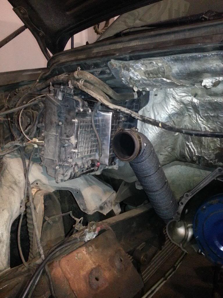
Wrapped up the wiring for the pusher pump and rerouted all the transmission and t.case wires. Got it looking like it should. 2 months ago I ripped it all apart and cleaned it up. I also fixed my heater box thingy. It's all hacked up because on a Ford SD you normally need to run the industrial manifold so the turbo doesn't hit the a/c box. I don't so the box has been modified to work for what I have. It's a reasonably tight fit but not too bad.
I had a loose connection for the blower motor so I fixed that too. I spent some time figuring out what the heck I'm going to do about the tach now that I'm running the fluidampr. Figured out what I need to do to modify the brackets. Did all I could with that and now I'll take what I can't do to the machine shop for a quick little job so it'll work. Other than that I put the fuel tank and skid plate back on when I finished the pusher...
All I need to do is wrap the downpipe before the motor can go back in I think. I'm excited!
Sent from Tapatalk 4 via a Galaxy S3
Tonight I got back to it again. No pictures though. Mostly just tying up loose ends so it isn't exciting stuff.
Wrapped up the wiring for the pusher pump and rerouted all the transmission and t.case wires. Got it looking like it should. 2 months ago I ripped it all apart and cleaned it up. I also fixed my heater box thingy. It's all hacked up because on a Ford SD you normally need to run the industrial manifold so the turbo doesn't hit the a/c box. I don't so the box has been modified to work for what I have. It's a reasonably tight fit but not too bad.
I had a loose connection for the blower motor so I fixed that too. I spent some time figuring out what the heck I'm going to do about the tach now that I'm running the fluidampr. Figured out what I need to do to modify the brackets. Did all I could with that and now I'll take what I can't do to the machine shop for a quick little job so it'll work. Other than that I put the fuel tank and skid plate back on when I finished the pusher...
All I need to do is wrap the downpipe before the motor can go back in I think. I'm excited!
Sent from Tapatalk 4 via a Galaxy S3
Registered User
Joined: Jul 2010
Posts: 199
Likes: 1
From: southern ontario Canada
were did you pick up the exhaust wrap ? I am thinking about thye turbo but the ex manifold well it's another story if I wrap it I feel i may crack it from heat shock . what was your thoughts thunder bay gets cold southern ontario GTA not so much
Thread Starter
Registered User
Joined: Oct 2008
Posts: 1,591
Likes: 11
From: Thunder Bay
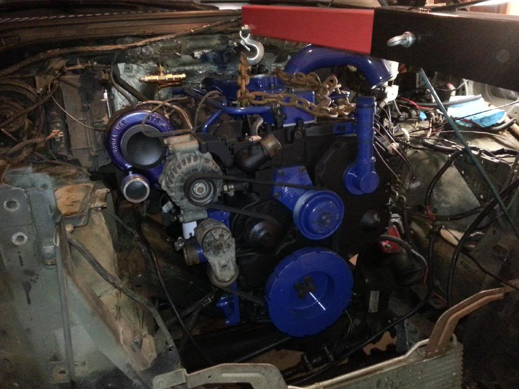
I got the exhaust wrap and the turbo blanket from ptp turbo blankets. I got the manifold blanket from levi. I can't remember the name of the site... I think it's turbo performance products. Looks like they've updated their stuff since I bought mine.
Also, believe it or not I am fairly certain the blankets make the shock on the metal less. My ats manifold still has the original paint on it after 2 years. They are notorious for having the paint come off within months. Reason being is metal warps and cracks when the cooling cycle happens to quickly. It essentially gets quenched. The blankets help cool them down slowly retaining the integrity of the metal. That's my opinion on it anyway. My turbo and manifold are still in really good shape. Even the bolts came off easily when it came apart to start this build.
Sent from Tapatalk 4 via a Galaxy S3
Thread Starter
Registered User
Joined: Oct 2008
Posts: 1,591
Likes: 11
From: Thunder Bay
No not with noise. It has helped massively with under hood temps and I changed a lot of other stuff at the same time but I'm pretty sure it has helped with spool up as well.
Overall, I would definitely do it again.
Sent from Tapatalk 4 via a Galaxy S3
Overall, I would definitely do it again.
Sent from Tapatalk 4 via a Galaxy S3
Thread Starter
Registered User
Joined: Oct 2008
Posts: 1,591
Likes: 11
From: Thunder Bay
Worked on the truck tonight and last night.
Last night involved getting the motor in the truck so let's get this started
Before I began with the motor I wrapped the downpipe with heat wrap and fixed the heater box. Doing this after the motor was in would be idiotic, and almost impossible...
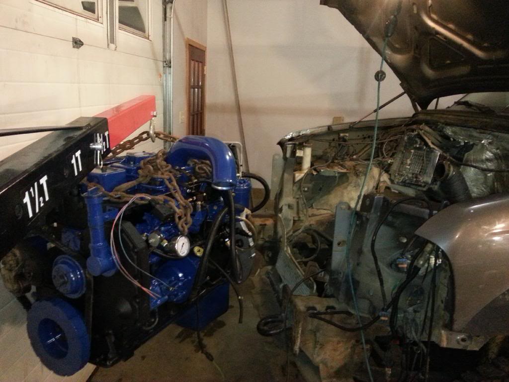
Now for the motor
Oh hey there, here's your new heart, truck meet motor
Steady...
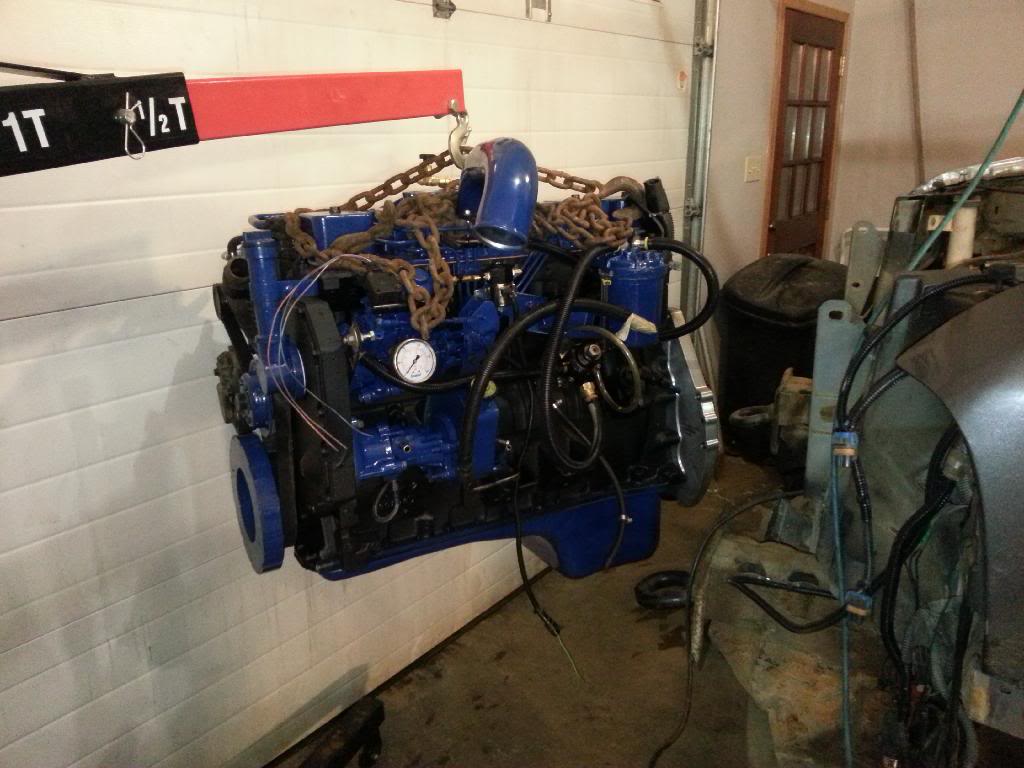
Steadddyyyy...
Almost...
Not quit...
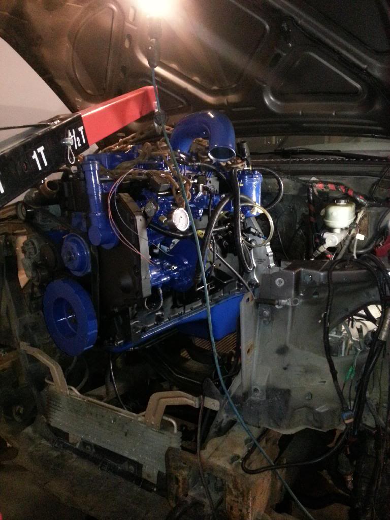
THERE!
And in it's new home
Once I got it in place I got the trans dipstick tube in place and put the adapter plate bolts in and the motor mounts in and tightened the bottom nuts on those then basically called it a night.
Last night involved getting the motor in the truck so let's get this started
Before I began with the motor I wrapped the downpipe with heat wrap and fixed the heater box. Doing this after the motor was in would be idiotic, and almost impossible...
Now for the motor
Oh hey there, here's your new heart, truck meet motor
Steady...
Steadddyyyy...
Almost...
Not quit...
THERE!
And in it's new home
Once I got it in place I got the trans dipstick tube in place and put the adapter plate bolts in and the motor mounts in and tightened the bottom nuts on those then basically called it a night.