
Beefing-Up My A518 Transmission (Updated As It Occurs)

Guest
Posts: n/a
BC, if that is a 48re front carrier you used and not an aftermarket, it has a shorter snout or hub (the part that sticks into the front annulus gear support). The 48re drive shell was thickened considerably so the front annulus support was thinned up roughly the same amount. If you used the 48re torlon bushing but the old thrust washer between the shell and the front annulus I'm wondering what could keep that torlon bushing from walking back towards the shell leaving almost none between the front carrier and the front annulus gear support. The front annulus support is the piece welded into the front annulus gear, the 48re front annulus gear is easy to spot, besides the thinner front annulus support the tooth count where the rear clutch discs engage the outside of the gear doubled. You might want to use a 47 bushing, they are longer than the 48 version.
Thread Starter
1st Generation Admin
Joined: Jan 2005
Posts: 4,601
Likes: 118
From: Buies Creek, NC
BC, if that is a 48re front carrier you used and not an aftermarket, it has a shorter snout or hub (the part that sticks into the front annulus gear support). The 48re drive shell was thickened considerably so the front annulus support was thinned up roughly the same amount. If you used the 48re torlon bushing but the old thrust washer between the shell and the front annulus I'm wondering what could keep that torlon bushing from walking back towards the shell leaving almost none between the front carrier and the front annulus gear support. The front annulus support is the piece welded into the front annulus gear, the 48re front annulus gear is easy to spot, besides the thinner front annulus support the tooth count where the rear clutch discs engage the outside of the gear doubled. You might want to use a 47 bushing, they are longer than the 48 version.
Again, THANKS!

Thread Starter
1st Generation Admin
Joined: Jan 2005
Posts: 4,601
Likes: 118
From: Buies Creek, NC
I must have done a good deed today . . . .
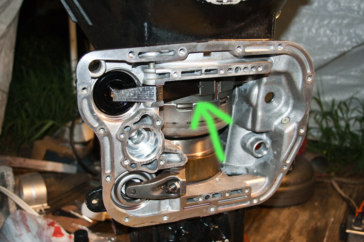
While in the final steps of reassembling the valve-body, I saw something out the corner of my eye . .. ..
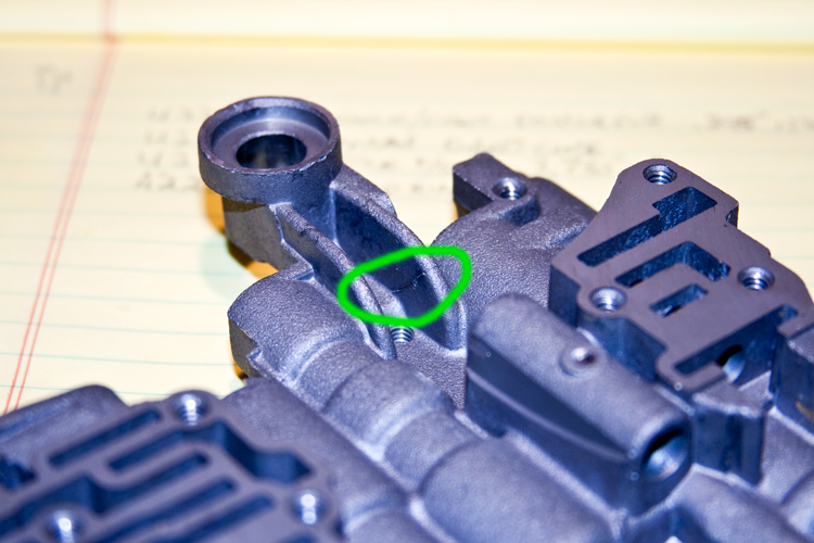
That's a crack in the shifter mount. Unless I'm mistaken, that particular part was originally from a wrecked truck. I guess the linkage took a beating. I don't know how it didn't break completely with me.
Thank goodness for spare parts.
While in the final steps of reassembling the valve-body, I saw something out the corner of my eye . .. ..
That's a crack in the shifter mount. Unless I'm mistaken, that particular part was originally from a wrecked truck. I guess the linkage took a beating. I don't know how it didn't break completely with me.
Thank goodness for spare parts.
Thread Starter
1st Generation Admin
Joined: Jan 2005
Posts: 4,601
Likes: 118
From: Buies Creek, NC
Truthfully, the way I happened to catch the crack was while I was assembling the upper, mid, and lower sections of the valve-body, I got to wiggling things around and I suppose I used that shifter mount as something of a handle.
A final step with each sub-assembly included flooding the sub-assemblies with clean trans fluid and working the spool-valves.
Using that shifter mount as a handle, moving around the wet assemblies, had the fluid collect in the crack and it would squeeze out when the crack was compressed (getting my attention).
With replacing the cracked part with a spare, I've cleaned the thing and have yanked, twisted and tugged firmly, and I can't make the crack stretch open. Considering the likelihood of failure being inversely proportional to it's desirability, the danged thing would have fallen out, at the worst moment had I left it be.

Getting back to your question, I think that if the crack were able to get bigger, allowing the shifter mount to actually move some, would have resulted in altering the shifter's spool-valve. Dunno . . . .
This post is brought to you by the color RED.


Registered User
Joined: Nov 2008
Posts: 417
Likes: 0
From: Goldendale, WA
Thread Starter
1st Generation Admin
Joined: Jan 2005
Posts: 4,601
Likes: 118
From: Buies Creek, NC
If this mess keeps up, it'll be a while (note heat index). Working on the roof is taking it's toll me these days. 
I'm still tinkering with the valve-body and hope to complete it tonight. I'd like to think I can complete the assembly of the trans by this Sunday . . . . . but then again Saturday's suppose to have a dry-bulb temperature of 100*. There's no telling how high the heat index will be above that.
Once the trans is complete, I've got a bag full of gaskets and seals with a couple of ball-bearings for the transfer case (virgin stock/OEM). It's output shaft has a nagging drip of lube oil.


Registered User
Joined: Nov 2007
Posts: 780
Likes: 42
Hey,
Since you've been through this twice- and your pushing more HP than many. Can you break your big parts replacement list into 2 groups: What you consider absolutely minimum for a A518. Then a second group of things- did you get the big oil hole aftermarket A618 intermediate shaft or a stocker? Do you consider the 5 gear planets a must have? What does it take to run the 48RE OD plates(23). I think if I can make them fit with an upgraded planetary set- that even the Rasydestos ones would work. Not sure how much HP/Torque before Kolene/Reds make sense.
Michael
Thread Starter
1st Generation Admin
Joined: Jan 2005
Posts: 4,601
Likes: 118
From: Buies Creek, NC
Hey,
Since you've been through this twice- and your pushing more HP than many. Can you break your big parts replacement list into 2 groups: What you consider absolutely minimum for a A518. Then a second group of things- did you get the big oil hole aftermarket A618 intermediate shaft or a stocker? Do you consider the 5 gear planets a must have? What does it take to run the 48RE OD plates(23). I think if I can make them fit with an upgraded planetary set- that even the Rasydestos ones would work. Not sure how much HP/Torque before Kolene/Reds make sense.
Michael
Since you've been through this twice- and your pushing more HP than many. Can you break your big parts replacement list into 2 groups: What you consider absolutely minimum for a A518. Then a second group of things- did you get the big oil hole aftermarket A618 intermediate shaft or a stocker? Do you consider the 5 gear planets a must have? What does it take to run the 48RE OD plates(23). I think if I can make them fit with an upgraded planetary set- that even the Rasydestos ones would work. Not sure how much HP/Torque before Kolene/Reds make sense.
Michael

I am by no means an expert with an automatic. The folks of these fine forums are witness to my experience.
1:
- Keep in mind, with the exception of the modified clutch-packs, the majority of the factory original hard-parts replaced in this rebuild were primarily replaced due to excessive wear as described in the FSM. Short of the racing mess, I don't know why the original design stuff wouldn't be a suitable replacement. I try to convince myself that those hard-parts beefed-up through the years by Dodge are a result of the increasing power output of the Cummins combined with the feedback from those fixing worn and broken parts since the release of each new design of the transmission.
It appears to me that if one were to keep the power demands limited (350ish HP? / no boosted launches), good condition stock parts (as defined by the FSM) and perhaps an increase in the pressures within the valve-body, etc, should be just fine.
Certainly I'm having to fix a broken shaft this go-round. But I'm also trying to identify why it broke, and what can be done to prevent it from happening again in similar conditions (racing). Looking back on the first rebuild, I did not consider normal wear regarding the hard-parts as perhaps being an issue (ignorance on my part) what with everything passing the FSM based inspection. Now looking at things from this new persepctive, I think the shaft broke as a result of all the combined slop in the well worn hard-parts and a stress-riser (being the root cause) in the spacer groove of the shaft. A 25psig (+) boosted launch probably didn't help either.
If you're gonna rebuild your mess, go ahead an strongly consider spending the extra time and effort to ensure all the bushings, bearings, shafts, thrust washers, gear teeth, etc are in good shape (toward the tight side of the FSM allowable tolerances?) along with a good general rebuild kit. The replacement bushings and bearing are comparatively inexpensive.
2:
- Based on the feedback I've gotten from asking questions to some of what many might call Big-Dawgs in the diesel trans world, considering my application (less than 600HP, NON lock-up converter, the truck's light weight), billet shafts are not required. If you do go to a newer 2nd gen intermediate shaft, you're gonna have to upgrade the front planet as the splines between the two have been changed from our original.
- Apparently, the change from aluminum planetary carriers to steel is a result of the propensity of the shaft splines to strip out of the carrier.
- The increase in pinion gears is a result of the increased thrust wear associated with the change from spur teeth to the helical teeth. Those same helical gears, while quieter than spur, just aren't as strong.
- I got the stock (2nd gen) intermediate shaft. While I may slightly enlarge the existing oil holes in it, I can't help but believe that the newly designed rear pilot bushing (with less lube oil bypassing) addresses some of this issue.
- The 48RE overdrive clutch upgrade stuff came from PATC. It pretty-much drops in with a modified reaction plate.
I think that if you're gonna go through all this mess, the 5-pinion, steel planets are the way to go (minimum). They are DEFINITELY less expensive that the 48RE stuff!

I sure hope I'm right.
* Hats off to fellow forum member txs for being a tremendous help in the finer but very important details.

Hope this helps more than confuses.

Thread Starter
1st Generation Admin
Joined: Jan 2005
Posts: 4,601
Likes: 118
From: Buies Creek, NC
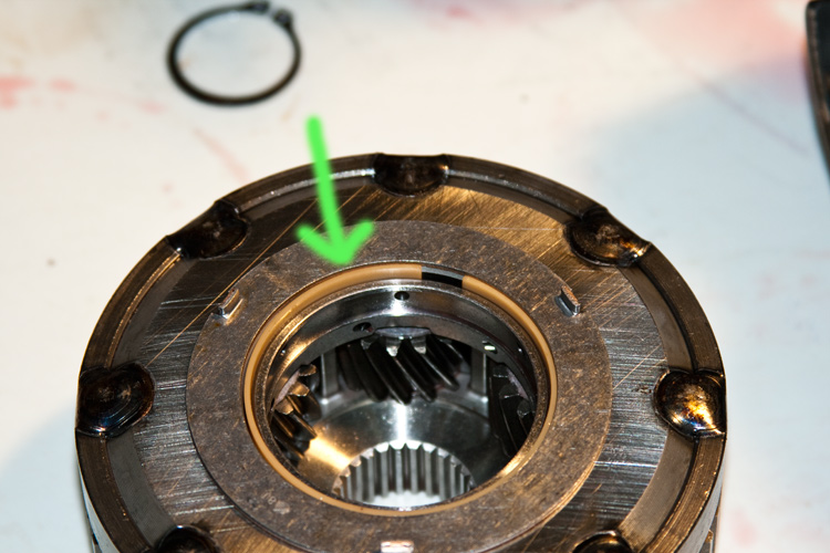
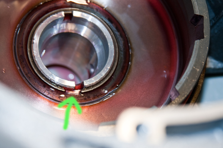
Speaking of fellow forum member txs, he suggested I look hard at the plastic sleeve bearing that goes between the front annulus support and the new planet. Sure enough, I need the wider of the two available so as to have it fit proper.
Here you can see the correct sleeve bearing nested inside the thrust washer . . .
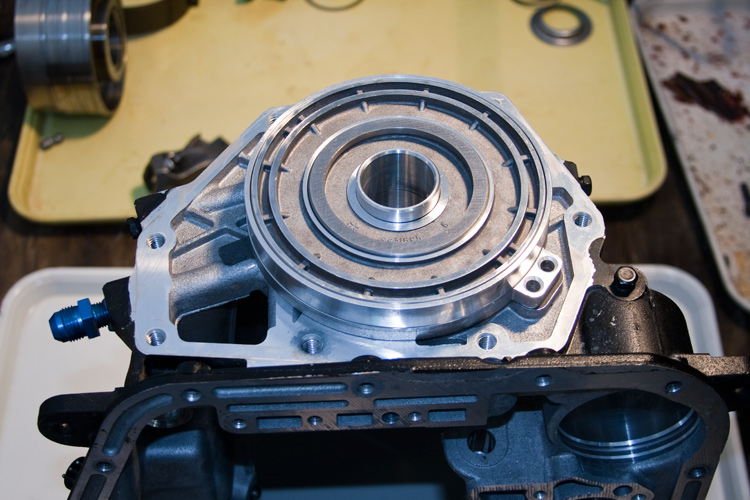
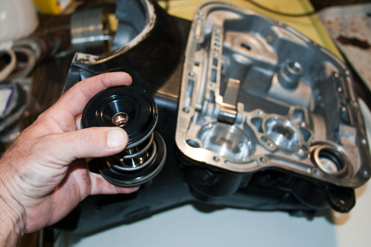
Alright, starting with a clean case, I reinstalled the upgraded overdrive piston and retainer. This one is from Sonnax and sports additional O-rings internally to help reduce oil leakage between it and the 3-speed case.
Moving over to the servo side of the case . . . .
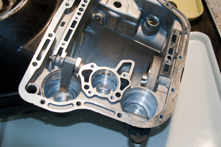
I start by installing the rear servo. This one has been modified to include springs and such to firm-up manual shifts (TransGo parts) . ..
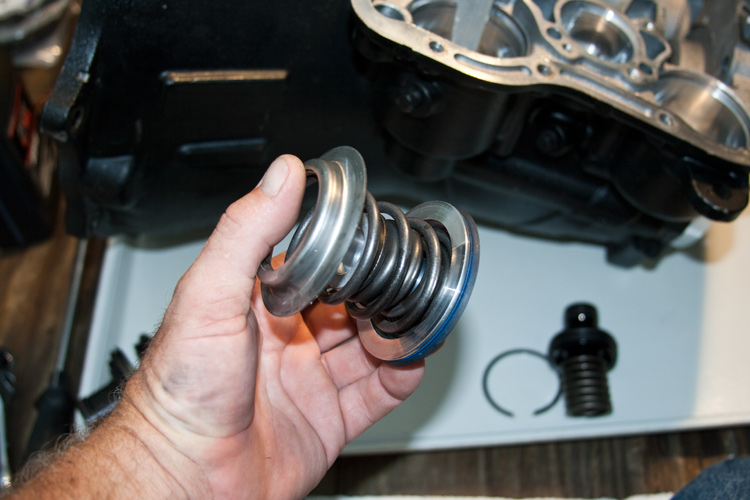
Gotta use them "Special" tools here . . . .
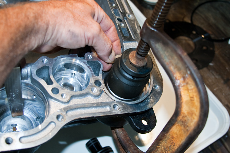
Next, install the modified front servo. It sports dual sealing rings around it's external perimeter as well as a dedicated seal and bronze bushing internally so as to reduce leakage.
I'm using an upgrade 4.2/1 ratio front band apply lever as I'm lead to believe the available 5/1 ratio lever might be too harsh. It provides more clamping effort for the front band.
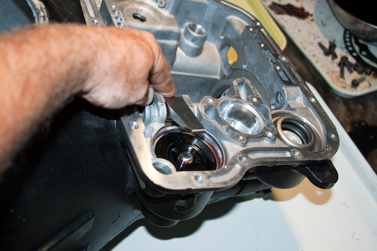
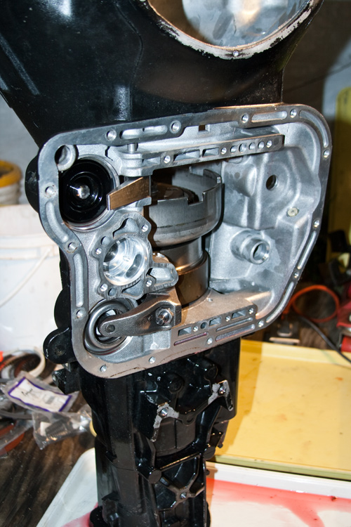
Now I need to slip in the reverse band and associated linkage . . .
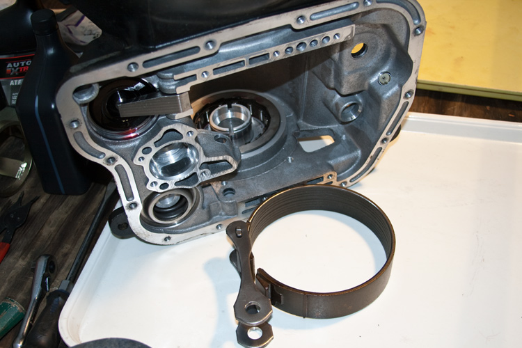
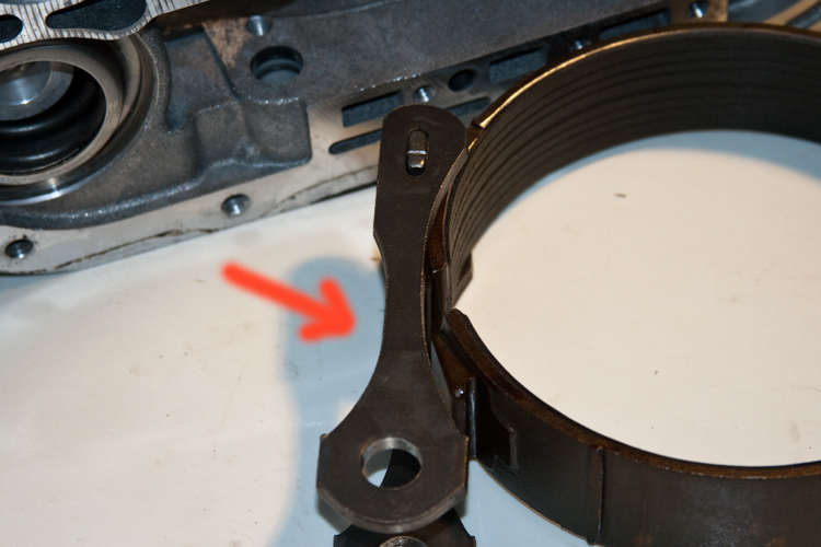
Those of you who're messing with such, be sure to install the linkage so the Notch in one side is away from the band.
Here you can see the correct sleeve bearing nested inside the thrust washer . . .
Alright, starting with a clean case, I reinstalled the upgraded overdrive piston and retainer. This one is from Sonnax and sports additional O-rings internally to help reduce oil leakage between it and the 3-speed case.
Moving over to the servo side of the case . . . .
I start by installing the rear servo. This one has been modified to include springs and such to firm-up manual shifts (TransGo parts) . ..
Gotta use them "Special" tools here . . . .
Next, install the modified front servo. It sports dual sealing rings around it's external perimeter as well as a dedicated seal and bronze bushing internally so as to reduce leakage.
I'm using an upgrade 4.2/1 ratio front band apply lever as I'm lead to believe the available 5/1 ratio lever might be too harsh. It provides more clamping effort for the front band.
Now I need to slip in the reverse band and associated linkage . . .
Those of you who're messing with such, be sure to install the linkage so the Notch in one side is away from the band.
Thread Starter
1st Generation Admin
Joined: Jan 2005
Posts: 4,601
Likes: 118
From: Buies Creek, NC
That way, when properly installed, the linkage will clear the rear servo housing inside the case . . . .
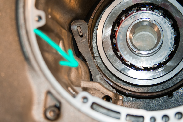
Now we can slip in the reverse drum. Y'all be sure that snap-ring is fully seated as there's a slight groove in the drum that the snap-ring rides in. If the snap-ring's not fully seated, things will bind.
Before I mount the overdrive section on the 3-speed case, I need to verify I'm running the correct overdrive piston spacer (I am ) . . .
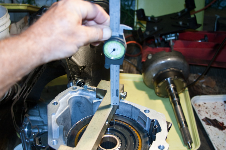
Then briefly sticking the intermediate shaft in the overdrive section ensures all the splines are aligned.
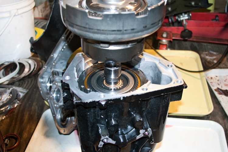
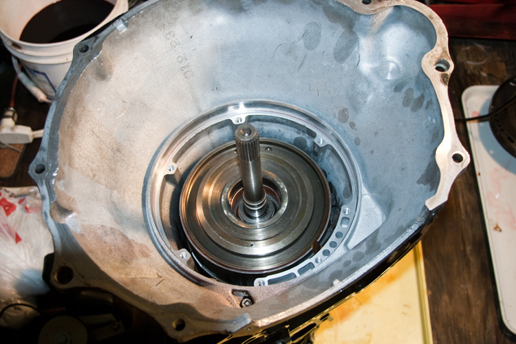
Now I can mount the overdrive section to the main case and drop in the intermediate shaft assembly.
Next I drop in the input shaft and clutch-pack assembly . . .
Followed by the front band and associated strut, etc . . .
Now we can slip in the reverse drum. Y'all be sure that snap-ring is fully seated as there's a slight groove in the drum that the snap-ring rides in. If the snap-ring's not fully seated, things will bind.
Before I mount the overdrive section on the 3-speed case, I need to verify I'm running the correct overdrive piston spacer (I am
) . . . Then briefly sticking the intermediate shaft in the overdrive section ensures all the splines are aligned.
Now I can mount the overdrive section to the main case and drop in the intermediate shaft assembly.
Next I drop in the input shaft and clutch-pack assembly . . .
Followed by the front band and associated strut, etc . . .