Trailer Wiring Upgrade
 08-02-2012, 10:00 PM
#1
Registered User
Thread Starter
Trailer Wiring Upgrade
When I hooked up the fiver, I found the brakes to be weak. I measured 8 volts at the splice near the axles. I also found that there was no battery feed from the truck nor backup lights, though the wires were in place. The truck wiring appeared to be pretty light, and there were multiple splices in it. Time to make it right.
Considerations:
Truck has about 11 amp load on the marker light circuit, with a few amps of instrument lighting on the same switch. Trailer marker light circuit is 12 - 15 amp draw. Second trailer adds another 4-5 amps.
Turn and brake signals need to have high reliability. If one shorts, it must leave the others working.
Battery feed to the trailer needs to support 30 amps or so with little voltage drop. It also needs to be protected to prevent fire, and switched so it is not connected when main engine is cranking, or when auxiliary is being used, ie listening to the radio when parked.
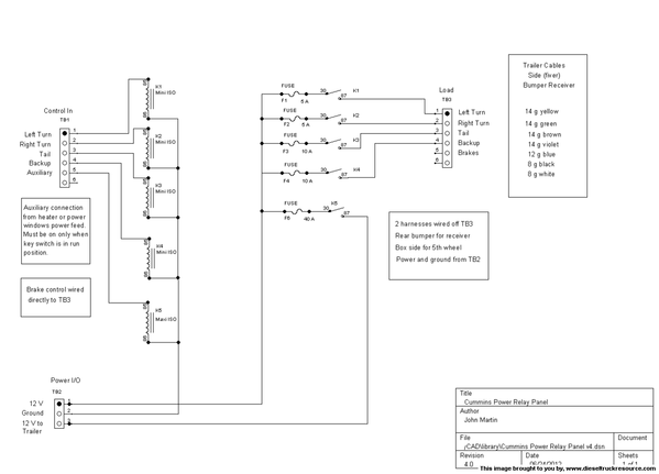
Relays and fuses for sure. Decided to make a load center just for the trailers. In addition to this, I added relays to the fiver to drive the second trailer off the fiver.
Here's the circuit design I came up with.
Considerations:
Truck has about 11 amp load on the marker light circuit, with a few amps of instrument lighting on the same switch. Trailer marker light circuit is 12 - 15 amp draw. Second trailer adds another 4-5 amps.
Turn and brake signals need to have high reliability. If one shorts, it must leave the others working.
Battery feed to the trailer needs to support 30 amps or so with little voltage drop. It also needs to be protected to prevent fire, and switched so it is not connected when main engine is cranking, or when auxiliary is being used, ie listening to the radio when parked.
Relays and fuses for sure. Decided to make a load center just for the trailers. In addition to this, I added relays to the fiver to drive the second trailer off the fiver.
Here's the circuit design I came up with.
 08-02-2012, 10:09 PM
#2
Registered User
Thread Starter
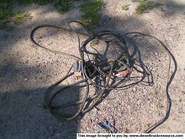
Tore out the old fire starter system.....er trailer wiring.
Next I dealt with the usual Dodge CTD wiring rat's nest at the battery positive terminal. I fabricated a mounting plate and installed an 8 point power distribution block and a ground stud. I fabricated another small panel to mount the 30 amp fuse for the transmission cooler that was just hanging and the 60 amp fuse for the trailer power panel.
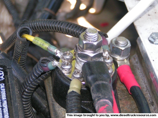
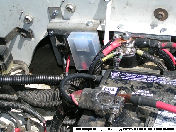
Next I dealt with the usual Dodge CTD wiring rat's nest at the battery positive terminal. I fabricated a mounting plate and installed an 8 point power distribution block and a ground stud. I fabricated another small panel to mount the 30 amp fuse for the transmission cooler that was just hanging and the 60 amp fuse for the trailer power panel.
08-02-2012, 10:15 PM
#3
Registered User
Thread Starter
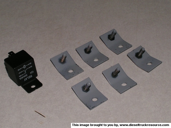
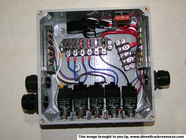
I wanted to mount the relays in a way that they could be serviced without breaking any waterproofing. I made these relay mounts out of 1 x 1.5 inch pieces of 14G steel and some 10-24 machine screws I had laying around.
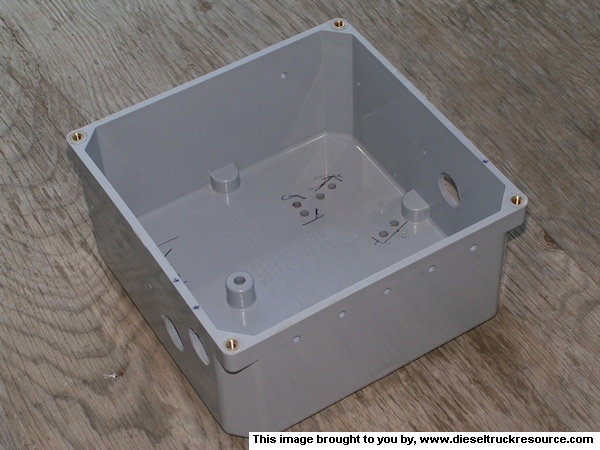
I played around with layout inside the junction box using double sided tape. Here's the test layout I came up with.
I marked and drilled the junction box for the components. I put the holes in for the 3/4" connectors with a step drill, and tapped them 3/4" NPT.
I played around with layout inside the junction box using double sided tape. Here's the test layout I came up with.
I marked and drilled the junction box for the components. I put the holes in for the 3/4" connectors with a step drill, and tapped them 3/4" NPT.
08-02-2012, 10:26 PM
#4
Registered User
Thread Starter
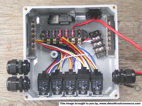
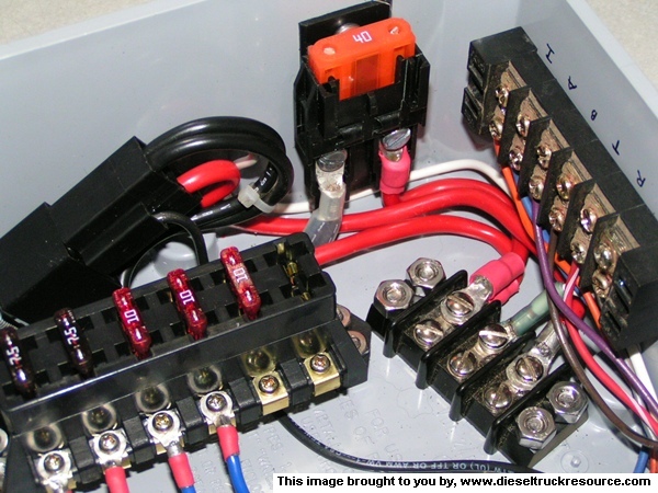
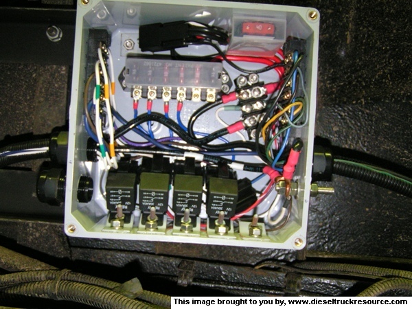
Terminal strips, fuse holders, and 70 amp relay installed in the box.
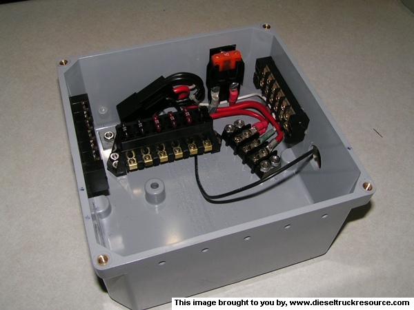
Here's a close up of the power relay. I happened to have a ring tongue terminal with 2 pieces of 10G crimped into it in my junk, so I crimped a .375 faston terminal on the other end for the relay socket and installed it. That's why there's 2 black wires close to each other at the relay. Wire to the fuse block is 8G and came on the block. 2 pieces salvaged from that are used to hook up the 40 amp fuse and 70 amp relay.
The 3 terminal power strip, left to right is, power in, ground, power to trailer.
I installed and wired the 40 amp relays. At the time these pictures were taken, I had a second relay in the trailer power circuit so I could logically add the ignition and accessory signals to apply power to the trailer. I found that logic already in the truck, and abandoned the switching relay. I now have a spare relay mount and socket.
here's a close up of the input side.
And the output side.
08-02-2012, 10:43 PM
#5
Registered User
Thread Starter
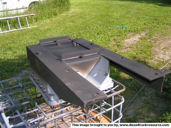
I fabricated an angle iron frame to fit up in the truck frame to mount the box. Here, it's been primed, the box bolted to it, and the exposed metal is treated with PermaTex ruberized coating.
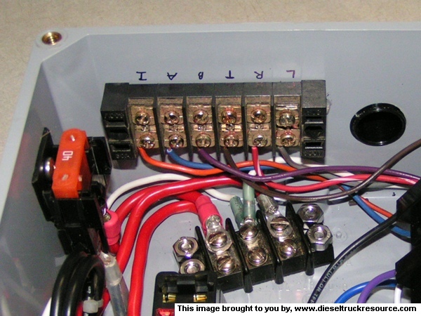
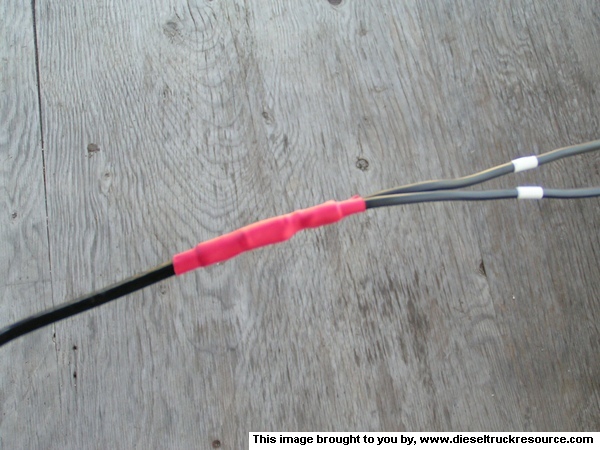
I installed the box and frame under the cab up in the frame and wired it up. Power from the front is 6 gauge, fused at 60 amps. Trailer brakes is 12 gauge, fused at 20 amps. LT, RT, Tail, and BU are spliced from the wiring harness in the frame going by the box. There were suitcase splices there before. I cut the wires and installed proper soldered and insulated splices and a loom to the wiring loom from the front.
Power and ground to the trailer is 6 gauge, spliced to 2 in hand 10 G just before the trailer connector. Power of course comes from the 70 amp relay. Ground is to frame via the stainless ground lug installed in the box, and also to the ground stud beside the 8 way power distribution near the battery.
Here's some shots of the junction box installed, and then covered.

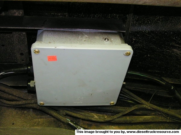
Now, when I stand on the brakes, it stops. All the trailer lights are nice and bright, and the battery fills up nicely while rolling. I also have no worries about a short burning down the rig and making one of those ugly black patchs you see beside the road from time to time.
I installed the box and frame under the cab up in the frame and wired it up. Power from the front is 6 gauge, fused at 60 amps. Trailer brakes is 12 gauge, fused at 20 amps. LT, RT, Tail, and BU are spliced from the wiring harness in the frame going by the box. There were suitcase splices there before. I cut the wires and installed proper soldered and insulated splices and a loom to the wiring loom from the front.
Power and ground to the trailer is 6 gauge, spliced to 2 in hand 10 G just before the trailer connector. Power of course comes from the 70 amp relay. Ground is to frame via the stainless ground lug installed in the box, and also to the ground stud beside the 8 way power distribution near the battery.
Here's some shots of the junction box installed, and then covered.
Now, when I stand on the brakes, it stops. All the trailer lights are nice and bright, and the battery fills up nicely while rolling. I also have no worries about a short burning down the rig and making one of those ugly black patchs you see beside the road from time to time.
08-02-2012, 10:51 PM
#6
Registered User
Thread Starter
Parts list for First Generation Relay Trailer Connection Box
Mounting Box.
Any suitable weatherproof enclosure will work. I used an IPEX 8x8x4 PVC wiring enclosure. Surplus, $10-$30 , new $40-$60. Another good surplus box is an outdoor wireless access point enclosure.
Barrier strips are also probably more easily obtainable at surplus or on eBay.
Through box ground stud was made by sawing the head off an all thread stainless bolt.
Cable connectors that you can jam 1/2" loom into.
Heyco 2324 Fastenal 0708899
Permatex blue or zep blue make - a - gasket to seal the connectors.
Description
Manufacturer MFG P/N Source P/n Quan.
Relay, Mini ISO 30 amp with mounting tab
Panasonic CB1F-M-12V Digikey 255-2730-ND 4
Relay, Maxi ISO &) amp with mounting tab
Panasonic CB1AH-M-12V Digikey 255-2079-ND 1
Socket, Tyco VCF4 (30 amp) and VCF7 (70 amp)
I found the VCF7 sockets at Digikey, as well as the maxi-ISO relay.
I found 30 amp relays with sockets for $25/10 on eBay. The wires are about 17G, but the sockets take TE connectors and clip together, making a neat install. The relays seem to be pretty good, especially for the price. eBay seller is saitronix
TE Connectors (manufacturer's part numbers) Enter the number at any supplier and get their number, price and availability. All are available at Digikey, but may be less expensive elsewhere.
.250 fastin/faston connectors, 5 positions on Mini socket. 2 (coil) on the maxi
180351-2 10 - 12 gauge
42281-2 14 - 18 gauge
There are many others that will work, but these are common and work well.
.375 fastin/faston connectors. Power contacts on maxi-ISO socket
280755-4 6(7) - 10 gauge
280756-4 10 - 12 gauge
6 gang ATO fuse block.
Del City p/n 73897
Maxi Fuse Block
Del City p/n 73886 Cover 73887
08-02-2012, 11:01 PM
#7
Registered User
Thread Starter
The empty watertight connector is for a gooseneck connector in the side of the box to be installed later, wired in parallel with the bumper connector. There's a piece of 1/2" CPVC with a cap installed now to seal it.
Trending Topics
 08-03-2012, 03:29 PM
#9
Registered User
Join Date: Dec 2010
Location: Land of the Toxic Avenger
Posts: 6,770
Received 1,637 Likes
on
1,112 Posts
Nice ! You do great work, Mr. J.
My Sparky would be so proud of you !

My Sparky would be so proud of you !
08-03-2012, 05:21 PM
#10
Registered User
Ummm...... Wow!! Not sure I followed all of that so well  .
. 
Looks great, J! I have a measely ol' relay under the rear of my truck for powering trailer lights when connected. It worked just fine the few times I've had a trailer connected. Of course, since I ditched the flatbed in favor of a pick-up bed, the 7-way blade connector has been removed temporarily until I can rewire everything. I think now I know just how it'll get wired .
.
. Looks great, J! I have a measely ol' relay under the rear of my truck for powering trailer lights when connected. It worked just fine the few times I've had a trailer connected. Of course, since I ditched the flatbed in favor of a pick-up bed, the 7-way blade connector has been removed temporarily until I can rewire everything. I think now I know just how it'll get wired
.
08-03-2012, 05:39 PM
#11
Registered User
Thread Starter
Ummm...... Wow!! Not sure I followed all of that so well .
Looks great, J! I have a measely ol' relay under the rear of my truck for powering trailer lights when connected. It worked just fine the few times I've had a trailer connected. Of course, since I ditched the flatbed in favor of a pick-up bed, the 7-way blade connector has been removed temporarily until I can rewire everything. I think now I know just how it'll get wired.
. Looks great, J! I have a measely ol' relay under the rear of my truck for powering trailer lights when connected. It worked just fine the few times I've had a trailer connected. Of course, since I ditched the flatbed in favor of a pick-up bed, the 7-way blade connector has been removed temporarily until I can rewire everything. I think now I know just how it'll get wired
.Anyway, thanks for the compliment.
08-03-2012, 08:19 PM
#13
Registered User
Join Date: Feb 2008
Location: north woods of Michigan
Posts: 550
Likes: 0
Received 0 Likes
on
0 Posts
Wow that is an awesome set up should be functional reliable and repairable. Just out of curiosity have you ever used circuit breakers on trailer wiring?
08-03-2012, 09:27 PM
#14
Registered User
Thread Starter
Thus, I use fuses on lighting circuits, and heavy charging circuits.
Breakers on brakes, or other critical functions.
There's certainly no reason other than preference to prevent you from using properly sized circuit breakers.
On relay mounting, one option I considered but rejected for esthetic reasons is a box mounted either on the floor behind the driver's seat or on the rear wall of the extended cab. Box wouldn't have to be weather tight, just cable runs through the floor, which could be handled with a little thumb gum.
10-28-2014, 02:08 PM
#15
Here's the circuit design I came up with.
[/QUOTE]
Any chance I could get a high res copy of this? When I zoom it, it pixelates and I can't read the numbers.
d9inger@gmail.com
[/QUOTE]Any chance I could get a high res copy of this? When I zoom it, it pixelates and I can't read the numbers.
d9inger@gmail.com