
Trailer lights isolation

Thread Starter
Registered User
Joined: Feb 2006
Posts: 326
Likes: 0
From: West Jordan, UT
Trailer lights isolation
For the last couple years, I have been reading several posts concerned with headlight switchs burning up. While my headlights are a concern and still running through the switch, I had a larger concern with my trailer running lights going through the switch.
This post is to give a few ideas to those who want to do the same thing and in my opinion, provides a better safer alternative to what I had installed.
A number of years ago, when I got the truck in 98 after my father in law passed on, I installed a trailer wiring kit on the truck that consisted of a harness that plugged into the tail lights and provided a 4-way flat plug. I converted that to a seven way RV plug adding the trailer brake line as well as a battery lead. This has worked well for 12 years, but the ground always needed to be redone every couple years as it was ground to the frame under neath.
My requirements were this.
- Use relays in a protected box
- Use Fuses where appropriate
- Get the ground in the engine compartment to protect it better.
- Use 7 way wiring cable from the relays to the plug for environmental protections and reliability.
First job was to find a suitable relay box. I wasn't finding what I wanted new, do I visited the local Pick and Pack yard. After looking at a lot of vehicles, I found that late 90's Crown Victoria's or Police Interceptors had a power ditribution box that looked promising.
Here it is after unbolting and removing it.

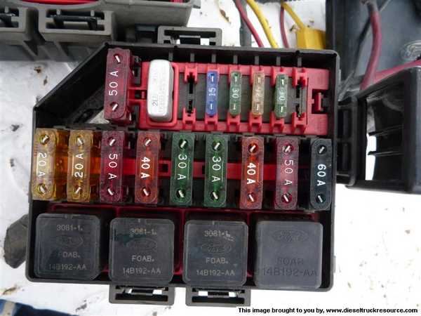
Looking at the relays and fuses, it looked to meet my requirements
Next was to figure how to disassemble the wiring in order to rewire it.
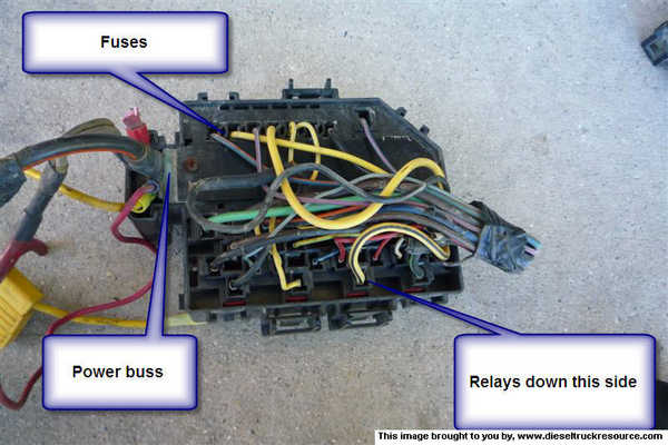
This shows the mess inside the box
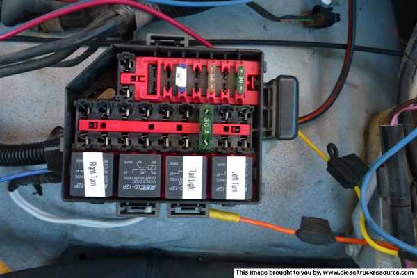
After disassembling the wires, buying some pigtails I wired it up. While not to Jim Lanes standards, It turned out nice. I used insulated barrel connectors from the cable to the pigtail. The pigtails were all 16 guage with a few 14 gauge.
Using relay schematics that are readily availble on this site, I figured which leads were signal, power and grounds.
It ended up looking like this. There are only fuses in for the few curcuits I have installed. There will be more as I add. This should relieve needing to place a wire on the battery and then fusing it.
This shows the box installed on the drivers side fender. The cable and signal wires are entering the box from the left. I used a ribbed cable cover to encase the signal wires. The signal wires for braked and turn come from the trailer adapter on the rear lights. The white wires are grounded to the fender. I need to add a battery ground to the fender also to make sure the grounds are sufficient. The yellow wires to the right have recently been relieved from duty and removed from the truck. The red wire connected to the blue wire is from the brake controller. I will be stringing a new wire from a curcuit breaker in the box to the brake controller back to the box and tied to the brake wire on the trailer cable.
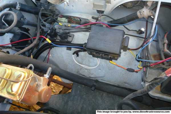
I kept the wire I got with the box. It looked to be sufficient in size. Right now, I have the running lights, turn signals, battery and power to my sleeper going through this box. Next step is to place the trailer brakes through the breaker you see in the box above.
I am pleased with this. the box bolted nicely to the fender. The trailer cable and the signal wires ran cleanly in the frame and wire tied nicely. The lights on the trailer are brighter. I will say that when I run flashers or turn signals and standing outside, the clicking under the hood is noticable
This post is to give a few ideas to those who want to do the same thing and in my opinion, provides a better safer alternative to what I had installed.
A number of years ago, when I got the truck in 98 after my father in law passed on, I installed a trailer wiring kit on the truck that consisted of a harness that plugged into the tail lights and provided a 4-way flat plug. I converted that to a seven way RV plug adding the trailer brake line as well as a battery lead. This has worked well for 12 years, but the ground always needed to be redone every couple years as it was ground to the frame under neath.
My requirements were this.
- Use relays in a protected box
- Use Fuses where appropriate
- Get the ground in the engine compartment to protect it better.
- Use 7 way wiring cable from the relays to the plug for environmental protections and reliability.
First job was to find a suitable relay box. I wasn't finding what I wanted new, do I visited the local Pick and Pack yard. After looking at a lot of vehicles, I found that late 90's Crown Victoria's or Police Interceptors had a power ditribution box that looked promising.
Here it is after unbolting and removing it.
Looking at the relays and fuses, it looked to meet my requirements
Next was to figure how to disassemble the wiring in order to rewire it.
This shows the mess inside the box
After disassembling the wires, buying some pigtails I wired it up. While not to Jim Lanes standards, It turned out nice. I used insulated barrel connectors from the cable to the pigtail. The pigtails were all 16 guage with a few 14 gauge.
Using relay schematics that are readily availble on this site, I figured which leads were signal, power and grounds.
It ended up looking like this. There are only fuses in for the few curcuits I have installed. There will be more as I add. This should relieve needing to place a wire on the battery and then fusing it.
This shows the box installed on the drivers side fender. The cable and signal wires are entering the box from the left. I used a ribbed cable cover to encase the signal wires. The signal wires for braked and turn come from the trailer adapter on the rear lights. The white wires are grounded to the fender. I need to add a battery ground to the fender also to make sure the grounds are sufficient. The yellow wires to the right have recently been relieved from duty and removed from the truck. The red wire connected to the blue wire is from the brake controller. I will be stringing a new wire from a curcuit breaker in the box to the brake controller back to the box and tied to the brake wire on the trailer cable.
I kept the wire I got with the box. It looked to be sufficient in size. Right now, I have the running lights, turn signals, battery and power to my sleeper going through this box. Next step is to place the trailer brakes through the breaker you see in the box above.
I am pleased with this. the box bolted nicely to the fender. The trailer cable and the signal wires ran cleanly in the frame and wire tied nicely. The lights on the trailer are brighter. I will say that when I run flashers or turn signals and standing outside, the clicking under the hood is noticable

Thread Starter
Registered User
Joined: Feb 2006
Posts: 326
Likes: 0
From: West Jordan, UT
I was rather surprised on how well this box fit. The bracket is attached with 3 bolts and with a few washers on one as shims, it fit nicely.
Thanks for the compliments.

Thread
Thread Starter
Forum
Replies
Last Post
ajpulley
3rd Gen High Performance and Accessories (5.9L Only)
2
Aug 27, 2008 10:44 PM