
How to install a Start & Stop switch.


Thread Starter
Administrator


Joined: Nov 2004
Posts: 4,084
Likes: 235
From: Southern California
Part-1
This has been on my list of things to do for quite some time now even before my ignition switch had failed. I am from the old school where to start an engine you would turn on your Master Switch, Wait for the green light and then Press the Start Button.
And then to shut down your engine you would idle down for a few minuets and then Turn OFF the Master Switch.
The main reason I put this on my truck is because of my entertainment system, I have a JVC KD-AVX1 receiver that plays CD�s and DVD movies and every time you turn the ignition off the stop the engine at any fast food drive through and quickly back on to listen to the radio or watch a DVD the system takes a few seconds to restart.
Also for security, every time I turn off my engine, the door locks will automatically Unlock this is part of my alarm system, now the doors will stay locked and I will have more time to relock them if I do need to turn the key to Off.
So now when I need to stop the engine I simply turn the switch to the LEFT and this opens the circuit to the fuel solenoid and stops the engine and since I never had to touch the ignition switch, the receiver never looses power. To restart the engine I simply move the gear selector into Neutral position and then now I turn the **** to the RIGHT and restart the engine.
OK now I bet your are thinking well how about if you are driving down the freeway and your little girl is fascinated with this new shiny **** on the dash and watched daddy turn it and she gives it a turn, wow there goes the starter right into the ring gear.
Nope, I wouldn�t make anything that could possibly be a danger to the engine or yourself.
I have built into this system an interlock relay that will allow you to start the engine with this switch but once the engine builds oil pressure the switch will be disabled, however you can still try and start the engine with the ignition switch it you prefer.
The Switch:
Being the critical component of this project I wanted to use something that was easy to get, has to meet my ultra heavy-duty specifications and above all it has to look good sitting in the dash of my Dodge Ram.
So first off this was not going to be no Hardware Store switch and besides where could you find one that was a Normally Open / Normally Closed with a spring return to center switch?
The perfect switch for me was found on all heave duty industrial machinery, it is used on the Start / Stop stations to control 3 phase motors and are available at Grainger�s.
The nice thing about these switches is that you can build them with as many sets of contacts or configurations as you like.
Now since I at this time not going to make this project to complicated for you if you wanted to do this for your truck I will make it easy to follow.
So lets get started.
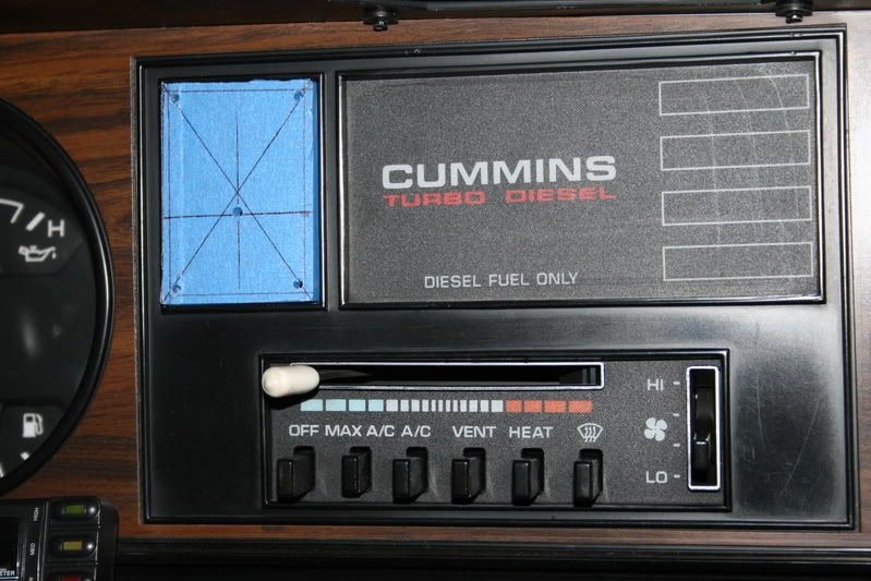
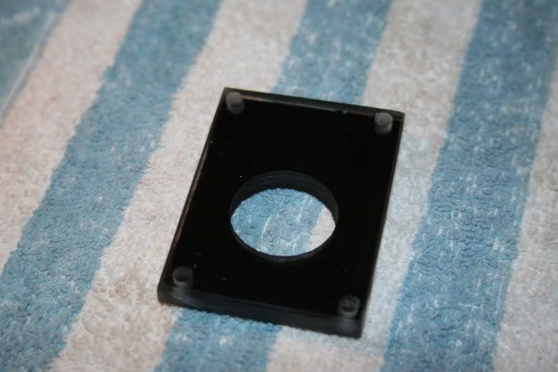
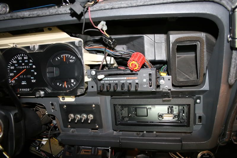
The location I chose is the blank cover to the left of the information center, it looks like it might have been a nice place to put a clock.
The plastic cover is held in with molded in clips so remove it carefully.
Then I measured it and transferred it to a piece of �� lexan, I was going to use a piece of aluminum and might still because I want to include some LED�s in it but for you this is a lot easier to work with.
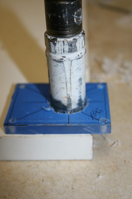
The inside hole is 7/8� and is drilled with a hole saw.
Go very slow with the saw, if you go fast it will melt the lexan and give you a ragged looking hole. The trick is to slow about 100 RPM, try this on a scrap piece first to get the feel.
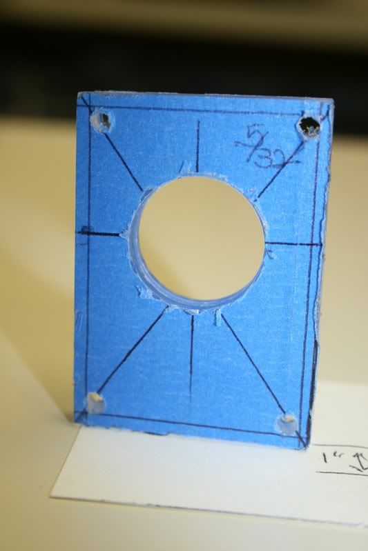
The dimensions of this is 1 �� wide X 2 7/16� high X �� thick, the 4 holes are 5/32� when you drill these you want then to be on the inside of the opening but spaced evenly so it looks symmetric.
Now here is the switch, or how it comes when you get the parts and you get to build the configuration you want.
I bought the switch as an assembly, it comes with (2) Normally open contact modules and then I bought (1) Normally Closed switch module extra.
You see the **** assembly the base and the switch assemblies.
The **** assembly has center off and momentary to both directions.
If you wish you could get this **** in different colors and illuminated by a LED. It just cost more money.
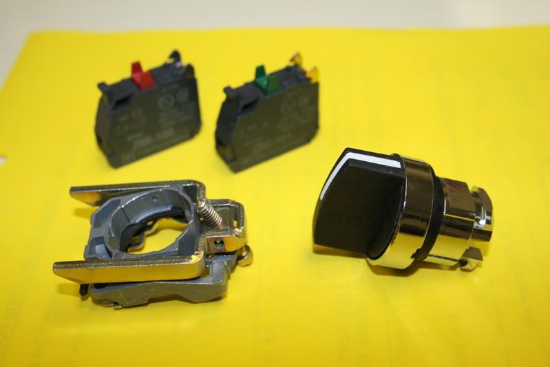
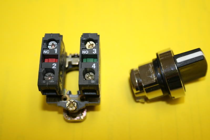
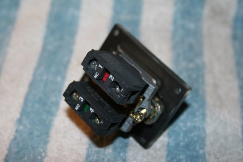
Here you see the Normally Open module, notice it has a GREEN button where as the Normally Closed has a RED button.
This switch is made by Telemecanique and is made in France.
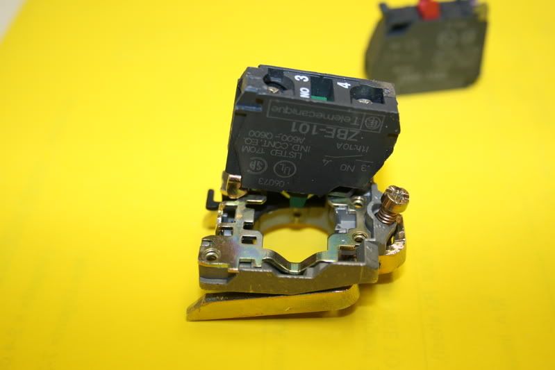
Here you can see how each switch module locks into the base, it is removed by releasing the clip with a small screwdriver.
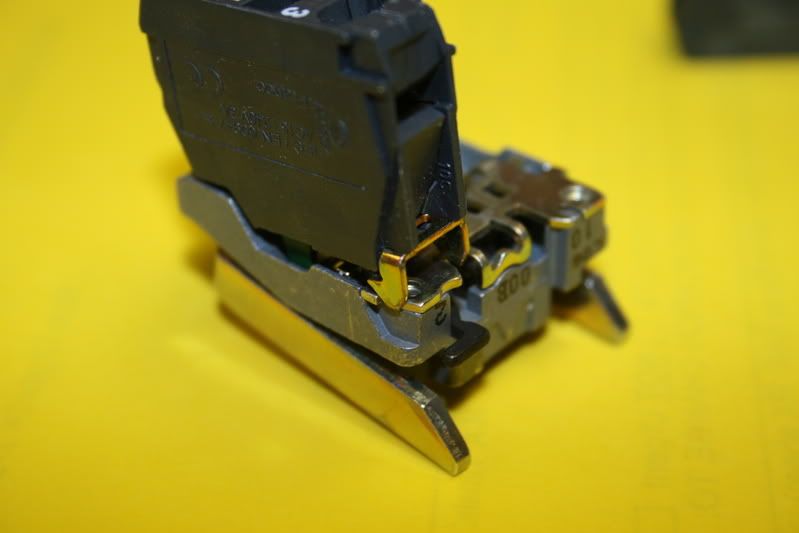
This is how the assembly looks loaded onto the base, if you wish you could stack as many switch modules as you needed piggyback to the end of the last switch.
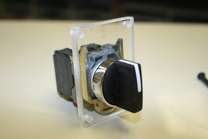
This a test fit of the switch into the lexan base I made. This entire switch is tool-less, the **** releases by lifting up on a lever.
Here I took the lexan and masked off the side facing you and then painted it with quick drying Semi Flat Black paint. Use a couple of light coats rather than one heavy one, you want this to look good.
Here we assemble the switch assembly onto the panel. You insert the **** through the hole with the rubber gasket on the outside, and then you install the base onto the **** that will only fit one way. If you use �� base like I did it will be a tight fit, it will click together as one unit.
Now carefully snug up the setscrew with a small screwdriver.
Caution at this point, if you use lexan slip a small piece of matchbook lid under the end of the screw so it does not scratch through the paint and you see it from the front.
This has been on my list of things to do for quite some time now even before my ignition switch had failed. I am from the old school where to start an engine you would turn on your Master Switch, Wait for the green light and then Press the Start Button.
And then to shut down your engine you would idle down for a few minuets and then Turn OFF the Master Switch.
The main reason I put this on my truck is because of my entertainment system, I have a JVC KD-AVX1 receiver that plays CD�s and DVD movies and every time you turn the ignition off the stop the engine at any fast food drive through and quickly back on to listen to the radio or watch a DVD the system takes a few seconds to restart.
Also for security, every time I turn off my engine, the door locks will automatically Unlock this is part of my alarm system, now the doors will stay locked and I will have more time to relock them if I do need to turn the key to Off.
So now when I need to stop the engine I simply turn the switch to the LEFT and this opens the circuit to the fuel solenoid and stops the engine and since I never had to touch the ignition switch, the receiver never looses power. To restart the engine I simply move the gear selector into Neutral position and then now I turn the **** to the RIGHT and restart the engine.
OK now I bet your are thinking well how about if you are driving down the freeway and your little girl is fascinated with this new shiny **** on the dash and watched daddy turn it and she gives it a turn, wow there goes the starter right into the ring gear.
Nope, I wouldn�t make anything that could possibly be a danger to the engine or yourself.
I have built into this system an interlock relay that will allow you to start the engine with this switch but once the engine builds oil pressure the switch will be disabled, however you can still try and start the engine with the ignition switch it you prefer.
The Switch:
Being the critical component of this project I wanted to use something that was easy to get, has to meet my ultra heavy-duty specifications and above all it has to look good sitting in the dash of my Dodge Ram.
So first off this was not going to be no Hardware Store switch and besides where could you find one that was a Normally Open / Normally Closed with a spring return to center switch?
The perfect switch for me was found on all heave duty industrial machinery, it is used on the Start / Stop stations to control 3 phase motors and are available at Grainger�s.
The nice thing about these switches is that you can build them with as many sets of contacts or configurations as you like.
Now since I at this time not going to make this project to complicated for you if you wanted to do this for your truck I will make it easy to follow.
So lets get started.
The location I chose is the blank cover to the left of the information center, it looks like it might have been a nice place to put a clock.
The plastic cover is held in with molded in clips so remove it carefully.
Then I measured it and transferred it to a piece of �� lexan, I was going to use a piece of aluminum and might still because I want to include some LED�s in it but for you this is a lot easier to work with.
The inside hole is 7/8� and is drilled with a hole saw.
Go very slow with the saw, if you go fast it will melt the lexan and give you a ragged looking hole. The trick is to slow about 100 RPM, try this on a scrap piece first to get the feel.
The dimensions of this is 1 �� wide X 2 7/16� high X �� thick, the 4 holes are 5/32� when you drill these you want then to be on the inside of the opening but spaced evenly so it looks symmetric.
Now here is the switch, or how it comes when you get the parts and you get to build the configuration you want.
I bought the switch as an assembly, it comes with (2) Normally open contact modules and then I bought (1) Normally Closed switch module extra.
You see the **** assembly the base and the switch assemblies.
The **** assembly has center off and momentary to both directions.
If you wish you could get this **** in different colors and illuminated by a LED. It just cost more money.
Here you see the Normally Open module, notice it has a GREEN button where as the Normally Closed has a RED button.
This switch is made by Telemecanique and is made in France.
Here you can see how each switch module locks into the base, it is removed by releasing the clip with a small screwdriver.
This is how the assembly looks loaded onto the base, if you wish you could stack as many switch modules as you needed piggyback to the end of the last switch.
This a test fit of the switch into the lexan base I made. This entire switch is tool-less, the **** releases by lifting up on a lever.
Here I took the lexan and masked off the side facing you and then painted it with quick drying Semi Flat Black paint. Use a couple of light coats rather than one heavy one, you want this to look good.
Here we assemble the switch assembly onto the panel. You insert the **** through the hole with the rubber gasket on the outside, and then you install the base onto the **** that will only fit one way. If you use �� base like I did it will be a tight fit, it will click together as one unit.
Now carefully snug up the setscrew with a small screwdriver.
Caution at this point, if you use lexan slip a small piece of matchbook lid under the end of the screw so it does not scratch through the paint and you see it from the front.
Thread Starter
Administrator
Joined: Nov 2004
Posts: 4,084
Likes: 235
From: Southern California
Part-2
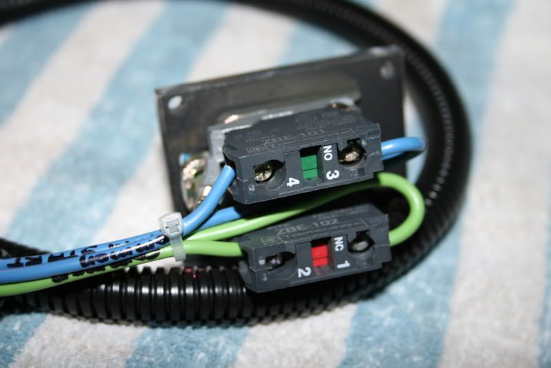
Ok now here I wired up the switches using 14-gauge automotive wire making the harness 24� long. I made them this long so after it is in place there is enough slack the harness that the dash trim can still be removed with ease.
Here you will see that the Normally Closed wire color is Green, since this is the Stop switch and will be controlling the fuel solenoid I changed the color to Blue to be consistent with the color code of the trucks electrical system.
I just did not want to confuse you. I then identified the wire using a Sharpie marker.
I next mounted the switch assembly into the opening and secured it into place using 4) #8-32x3/4� machine screws, flat washers and nuts.
If you measured and cut this correctly the panel will fit into the recess where the cover came out.
Use something that looks nice because you will see your finished work everytime you get into your truck. I used Black Stainless Steel Button Head Security Head screws to hold mine in.
I was going to use shiny SS Button Head Socket Head screws but I forgot where I put them so I will save them for another project.
I am assuming you know to get to this point to remove the face that you know that you need to lower the steering column by loosening the 2 nuts at either side, but before you do this, set the parking brake and then put the selector into 3rd gear now look where the column enters the dash and carefully remove the wire for the gear selector where it hooks into the arm, I tied about 3 inches of fishing line to the hook so it is easy to maneuver to replace and adjust then leave it on when you are done. I use a small pair of hemostats to manipulate the cable.
Here is the part where you will be dropping the wires down through the dash, you want them to go behind the heater controls just to the rear of the white plastic brace that supports the switch and then they will come out the bottom of the dash around the left side of the ashtray.
At this time I had alreadt spent about 20 minuets taking the cover off the cluster and cleaning out all of the dust and smog from the dash parts. It just looks cleaner now.
Ok now here you see the dash is going back together; be sure all of the spring clips are in place so there re no rattles later on and then replace all of the screws around the top.
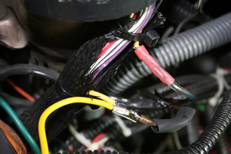
Next with the plastic cover removed that retains the fuse panel find the wires that exit from the steering column and carefully open the loom and now find the Yellow, this is the wire and this is where you will splice into.
This is where I cut in for the starter interrupt for my alarm system so if you were to break this circuit like I did and connect it to a hidden switch somewhere in your cab you just installed a Starter Cut Out switch and with this switch open the starter will not crank.
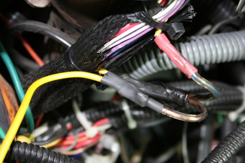
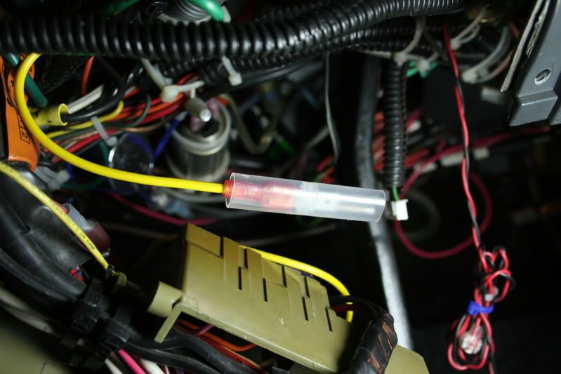
Anyhow you see I spliced my new yellow wire and soldered the connections after first slipping on a section of heat shrink tubing.
Then using my heat gun I shrunk the tubing into place making a nice and tight connection.
I then rebundled the wires and covered them with a section of convoluted tubing and secured it with a few ties.
Here is the lead I had just spliced into the harness; it is about 6� long making it comfortable enough to work under the dash.
Notice the kind of connectors I use, there I got at my HVAC supplier, I love these things.
This is where I got the (+) 12-volt lead for the relay circuit, I soldered the Red 14-gauge wire onto the buss for the blower circuit while the other end connects to an ATO fuse as an inline
As you can see I am feeding this circuit with a 6-gauge wire connected through a 70-amp relay to the battery. I guess my fuse panel is a bit modified.
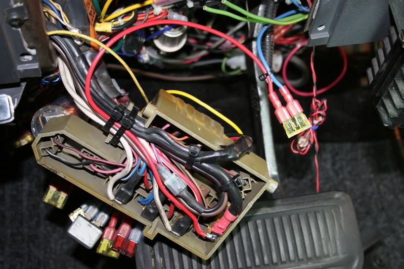
This is how it should be looking up to this point and besides I like showing it off.
I have had the doors open and the hood open for about 10 hours now so you can see my battery voltage is starting to dip.
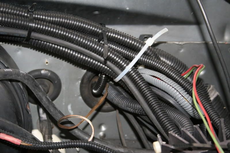
Now to the outside, this is the grommet next to the bulkhead connector, I had to cut a few new holes through it so I could get some more wires through it.
Ok now here I wired up the switches using 14-gauge automotive wire making the harness 24� long. I made them this long so after it is in place there is enough slack the harness that the dash trim can still be removed with ease.
Here you will see that the Normally Closed wire color is Green, since this is the Stop switch and will be controlling the fuel solenoid I changed the color to Blue to be consistent with the color code of the trucks electrical system.
I just did not want to confuse you. I then identified the wire using a Sharpie marker.
I next mounted the switch assembly into the opening and secured it into place using 4) #8-32x3/4� machine screws, flat washers and nuts.
If you measured and cut this correctly the panel will fit into the recess where the cover came out.
Use something that looks nice because you will see your finished work everytime you get into your truck. I used Black Stainless Steel Button Head Security Head screws to hold mine in.
I was going to use shiny SS Button Head Socket Head screws but I forgot where I put them so I will save them for another project.
I am assuming you know to get to this point to remove the face that you know that you need to lower the steering column by loosening the 2 nuts at either side, but before you do this, set the parking brake and then put the selector into 3rd gear now look where the column enters the dash and carefully remove the wire for the gear selector where it hooks into the arm, I tied about 3 inches of fishing line to the hook so it is easy to maneuver to replace and adjust then leave it on when you are done. I use a small pair of hemostats to manipulate the cable.
Here is the part where you will be dropping the wires down through the dash, you want them to go behind the heater controls just to the rear of the white plastic brace that supports the switch and then they will come out the bottom of the dash around the left side of the ashtray.
At this time I had alreadt spent about 20 minuets taking the cover off the cluster and cleaning out all of the dust and smog from the dash parts. It just looks cleaner now.
Ok now here you see the dash is going back together; be sure all of the spring clips are in place so there re no rattles later on and then replace all of the screws around the top.
Next with the plastic cover removed that retains the fuse panel find the wires that exit from the steering column and carefully open the loom and now find the Yellow, this is the wire and this is where you will splice into.
This is where I cut in for the starter interrupt for my alarm system so if you were to break this circuit like I did and connect it to a hidden switch somewhere in your cab you just installed a Starter Cut Out switch and with this switch open the starter will not crank.
Anyhow you see I spliced my new yellow wire and soldered the connections after first slipping on a section of heat shrink tubing.
Then using my heat gun I shrunk the tubing into place making a nice and tight connection.
I then rebundled the wires and covered them with a section of convoluted tubing and secured it with a few ties.
Here is the lead I had just spliced into the harness; it is about 6� long making it comfortable enough to work under the dash.
Notice the kind of connectors I use, there I got at my HVAC supplier, I love these things.
This is where I got the (+) 12-volt lead for the relay circuit, I soldered the Red 14-gauge wire onto the buss for the blower circuit while the other end connects to an ATO fuse as an inline
As you can see I am feeding this circuit with a 6-gauge wire connected through a 70-amp relay to the battery. I guess my fuse panel is a bit modified.
This is how it should be looking up to this point and besides I like showing it off.
I have had the doors open and the hood open for about 10 hours now so you can see my battery voltage is starting to dip.
Now to the outside, this is the grommet next to the bulkhead connector, I had to cut a few new holes through it so I could get some more wires through it.
Thread Starter
Administrator
Joined: Nov 2004
Posts: 4,084
Likes: 235
From: Southern California
Part-3
Here is the Blue wire we will be splicing into, it is the one that is in a bundle that comes from the injection pump, the Yellow that connects to the Blue / White stripe wire is from the KSB solenoid.
This connection is at the rear of the engine above the starter and just outboard of the fuel filter.
What I did was to cut this wire,
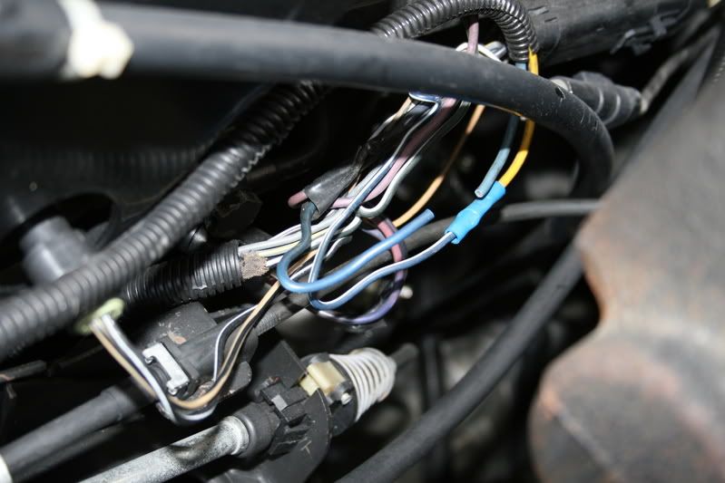
And then I spliced my 2 Blue wires from my harness I just installed into the factory harness.
The wire that comes from the harness that has (+) 12 volts with the key on will go to the common terminal on the dash switch while the Normally Closed terminal returns to continue on to the fuel solenoid.
After I soldered and checked all of my connections I slid over the heat shrink tubing and then using my heat gun shrink them for a nice finished connection.
You will also see the Green wire in the harness, this will continue around the rear of the engine and wind up by the alternator.
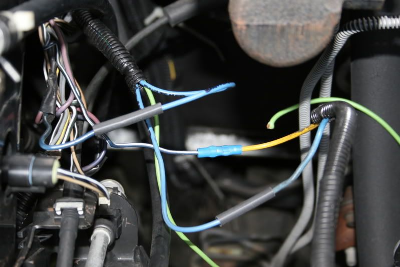
When all of the connections are completed and checked I closed them up and bundled it with convoluted tubing finished with a few ties.
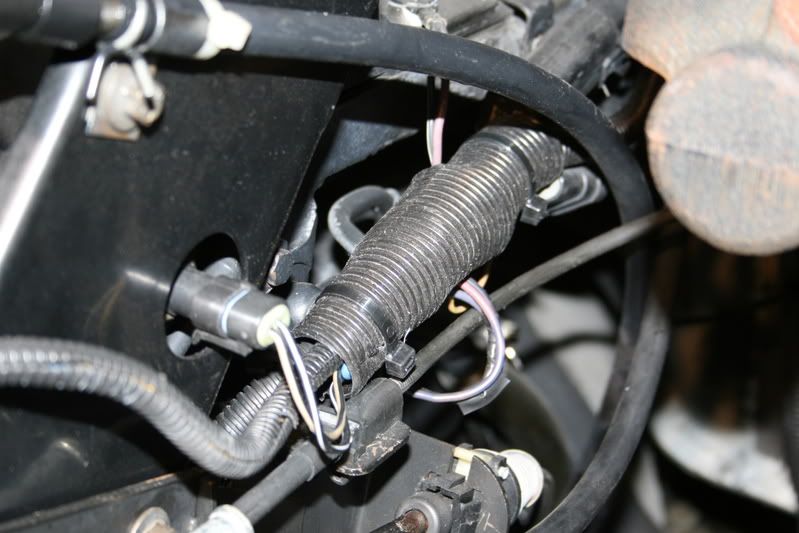
The Green wire travels the top of the engine inside that �� convoluted tubing along the water line along with my 2-gauge alternator lead.
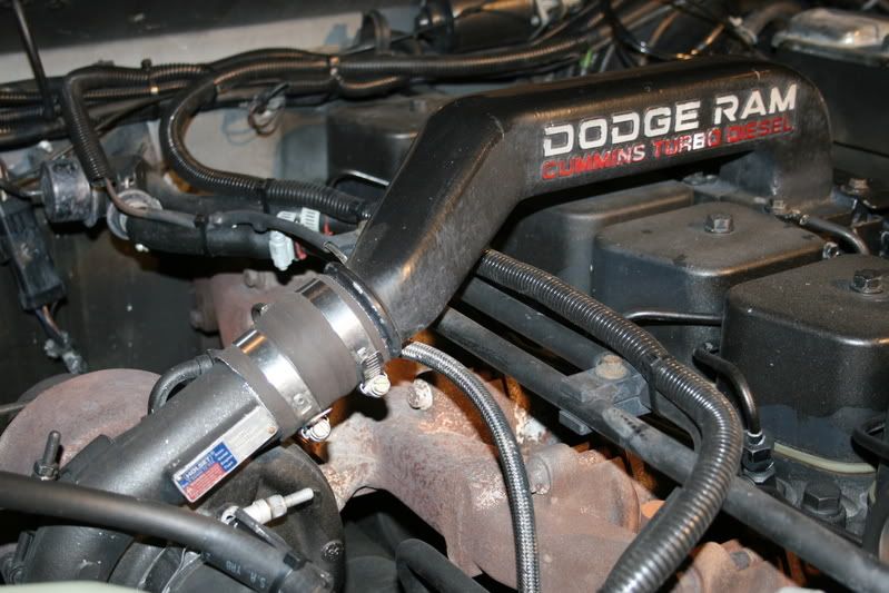
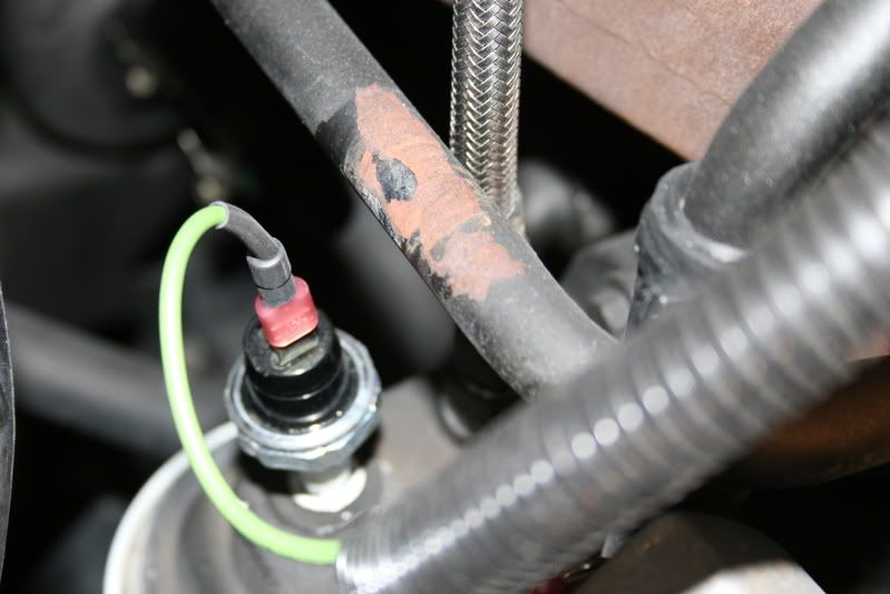
Here on the top of the oil filter adapter I installed my Oil Pressure Switch into the 1/8� NPT hole.
On my installation I have a Hobbs Switch installed but for demonstration purposes I am using the pictured switch. You can use the Hobbs Switch like I did if you wish but they are $50.00 each opposed to $9.73.
Note: You can alternately install this Oil Pressure Switch on a Tee along with the stock Oil Sender if you wish and save running the extra length of wire if you wish, this is up to you.
Dress all of the wires to keep them out of the way of anything that will become hot and then you are finished for the work done under the hood.
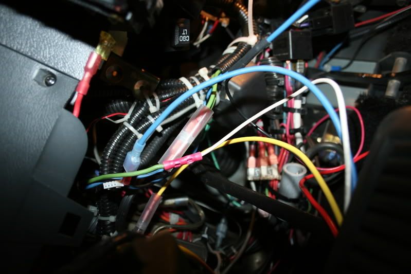
This is a view of under the dash so you can see the placement of the wiring.
In the center you see the 2 Nylon butt connectors, they are the connection between the switch and the harness that leads into the engine compartment.
The Yellow wire is the lead to the starter connection we made under the column while the ATO fuse on the left side supplies the power for the interlock relay.
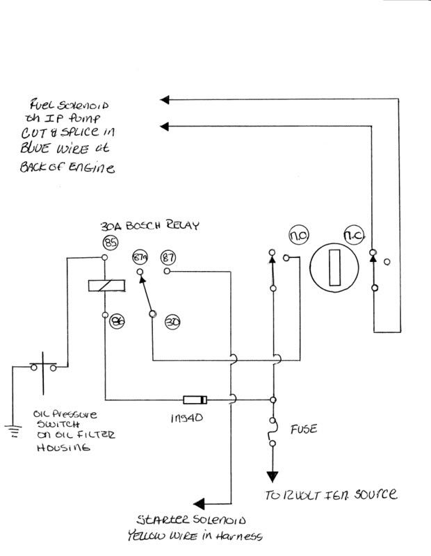
Here I will explain the circuit and how it works, starting with the 30-amp Bosch Relay you see:
Term. #86 gets (+) 12 volts (ignition controlled) through the 1N540 3-amp diode (I installed this diode only to reduce the voltage to the relay coil since it is always on, also observe the band that goes toward the source) to the new connection I soldered onto the Fuse Panel through the ATO fuse I configured as an inline.
Term. #85 the ground side of the relay completes its path through the Normally Closed Oil Pressure Switch we mounted onto the oil filter adapter.
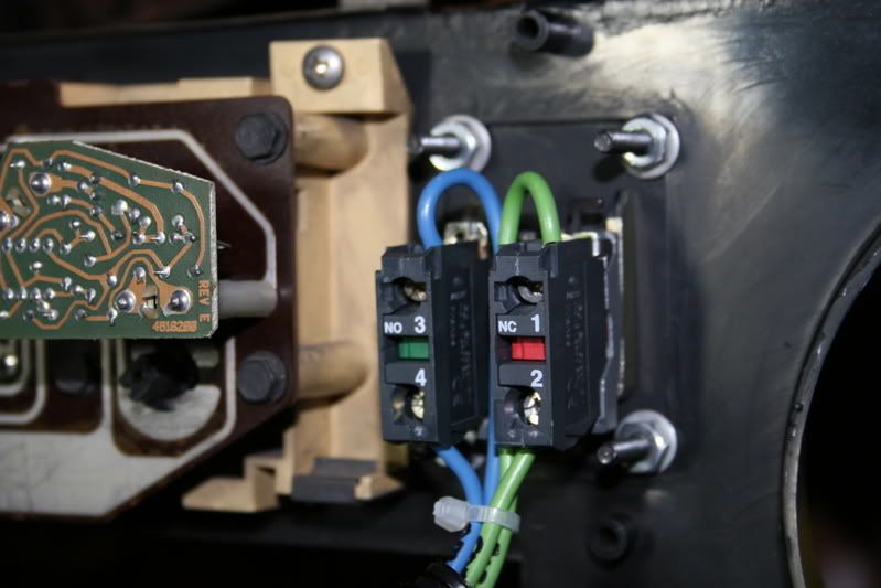
On the right side we see the 2 different sets of contacts contained into the switch that is mounted in the dash.
On the Normally Open set, the common lead receives its (+) 12 volts from the same connection as the relay is connected. While the switched terminal of the switch feeds
Term. #30 of the relay and then,
Term. # 87 of the relay connects into the connection we made under the steering column thorough the Yellow wire.
Now to the set of switch contacts on the right side, the Blue wire that was spliced into the harness at the engine that has the (+) 12 volts when the key is on will go to the Common or bottom terminal in the picture and the remaining terminal from the switch will return to the connection leading to the fuel solenoid.
Note while the polarity of these connections are not critical meaning you can connect them either way I like to follow a standard scheme and have the power into the common of the switch.
Here is how it works:
To START your engine.
� You turn on your ignition switch to the RUN position,
� The relay coil has power and the ground is provided through the Normally Closed contacts of the Oil Pressure Switch. The relay clicks IN.
� You turn the switch **** to the RIGHT and this completes the circuit through the relay contacts to the Starter circuit and begins to crank the starter.
� Now that the engine has started the oil pressure builds up past the set 2-7.7 PSI settings of the oil pressure switch and then the relay will drop OUT opening the circuit to the starter.
� This describes how the safety interlock works; now if you were to accidentally turn the switch to the Start position it will do nothing.
� Once the engine has been shut down and the oil pressure drops below 2-7.7 PSI it will now function again. Remember this if you try to crank your engine over like trying to find your timing mark, it will disable itself.
To STOP your engine.
� While the engine is running whenever you need to stop, turn the **** to the LEFT and this will interrupt the battery feed to the Fuel solenoid mounted in the injection pump and immediately bring the engine to a to a STOP, while leaving all of the ignition powered circuits still powered ON.
If you were to be in a drive through, simply move the gear selector into NEUTRAL or depress the clutch if you have a manual and then turn the **** to the RIGHT and the engine will come to life.
This is a list of the parts we are going to use and where I got them.
1 Selector Switch, 22mm. PN#6HK61 Grainger�s @$41.90 each
1 Contact Block ( N/C Switch) PN#6HZ09 Grainger�s @10.09 each
1 Oil Pressure Switch PN#OP6384 Napa @8.99 each
1 40 amp Bosch Relay PN#0-332-209-138 BPS Truck Parts @4.75 each
or 30 amp Bosch Relay PN#0-332-209-150 @4.75 each
1 Relay Harness PN#24964 @3.95 each
1 1N540 3 amp Epoxy Diode PN#276-1141 Radio Shack
Miscellaneous:
14-gauge automotive wire, Lexan or material to construct panel, Required screws and nuts to secure the panel, Terminals, Convoluted tubing or loom as needed.
Tools Required:
General electrical working tools, saw or cutter to cut panel, 7/8 hole saw, Drill Bits.
Oil Pressure switch 2-7.7 PSI
http://www.napaonline.com/NOLPPSE/(S...384_0152312741
Switch Assembly.
http://www.grainger.com/Grainger/wwg...=17&submit.y=6
Switch contacts.
http://www.grainger.com/Grainger/wwg...=16&submit.y=6
More switches.
http://www.grainger.com/Grainger/wwg...ue&CatPage=326
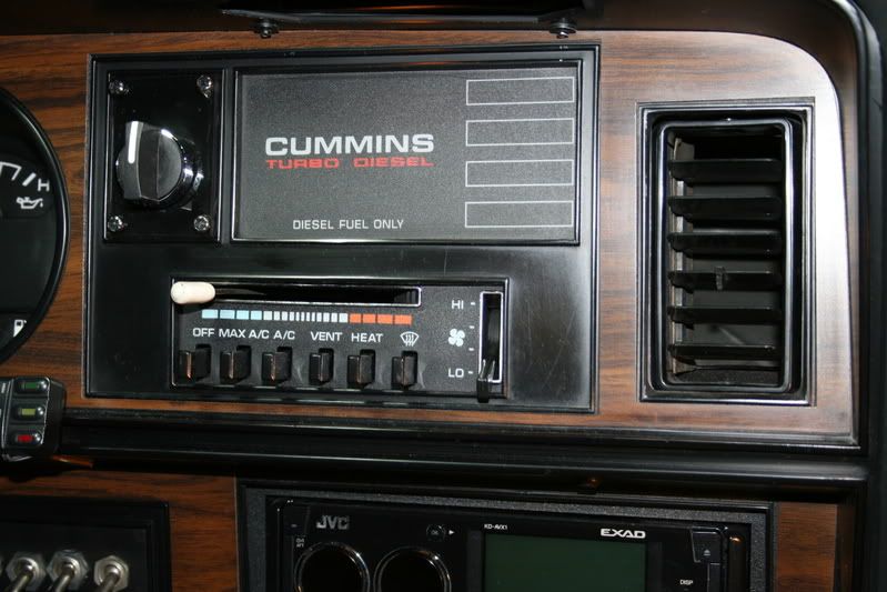
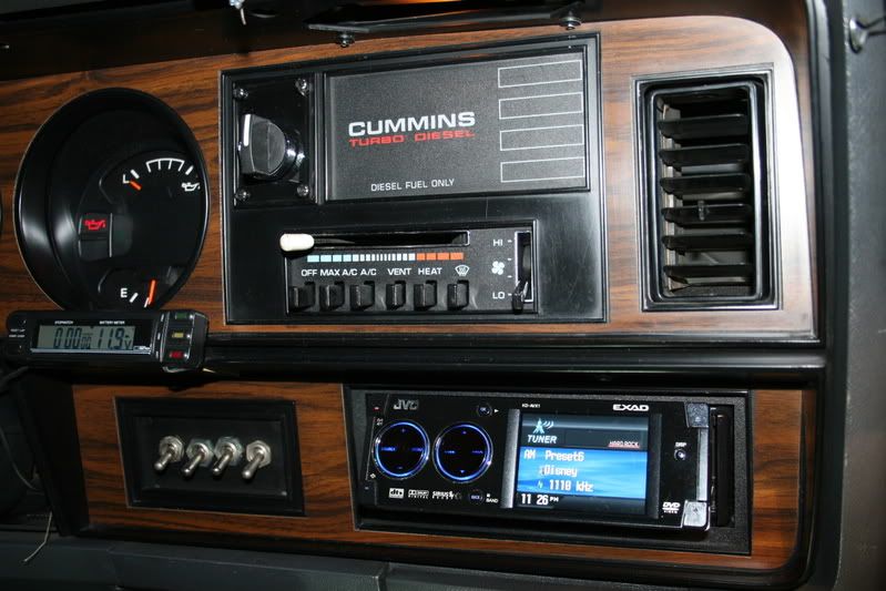
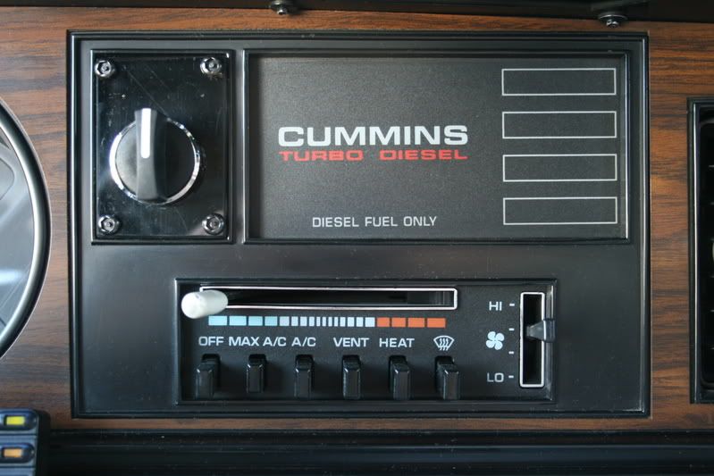
Here is what the finished job should look like, I was either going to use a Push / Pull configuration switch or this ON-OFF-ON one but I figured the plastic dash might suffer without strengthen it a bit, this option again is up to you.
This takes a bit getting used to since it is almost a primitive habit of twisting the key past ON to start your engine but I almost never go for the key anymore.
An option to this I am going to bypass the transmission interlock with a pushbutton so I do not have to take it out of gear that will be under a spring loaded cap.
Once this modification is installed then the ignition switch should last the life of the truck.
I hope this is something you will be able to use on your truck and thank you for letting me instruct you along the way.
Oh yes I forgot, this system is designed to be Fail Safe so if any component should fail the system will always work in the traditional manner.
Jim in California.
Here is the Blue wire we will be splicing into, it is the one that is in a bundle that comes from the injection pump, the Yellow that connects to the Blue / White stripe wire is from the KSB solenoid.
This connection is at the rear of the engine above the starter and just outboard of the fuel filter.
What I did was to cut this wire,
And then I spliced my 2 Blue wires from my harness I just installed into the factory harness.
The wire that comes from the harness that has (+) 12 volts with the key on will go to the common terminal on the dash switch while the Normally Closed terminal returns to continue on to the fuel solenoid.
After I soldered and checked all of my connections I slid over the heat shrink tubing and then using my heat gun shrink them for a nice finished connection.
You will also see the Green wire in the harness, this will continue around the rear of the engine and wind up by the alternator.
When all of the connections are completed and checked I closed them up and bundled it with convoluted tubing finished with a few ties.
The Green wire travels the top of the engine inside that �� convoluted tubing along the water line along with my 2-gauge alternator lead.
Here on the top of the oil filter adapter I installed my Oil Pressure Switch into the 1/8� NPT hole.
On my installation I have a Hobbs Switch installed but for demonstration purposes I am using the pictured switch. You can use the Hobbs Switch like I did if you wish but they are $50.00 each opposed to $9.73.
Note: You can alternately install this Oil Pressure Switch on a Tee along with the stock Oil Sender if you wish and save running the extra length of wire if you wish, this is up to you.
Dress all of the wires to keep them out of the way of anything that will become hot and then you are finished for the work done under the hood.
This is a view of under the dash so you can see the placement of the wiring.
In the center you see the 2 Nylon butt connectors, they are the connection between the switch and the harness that leads into the engine compartment.
The Yellow wire is the lead to the starter connection we made under the column while the ATO fuse on the left side supplies the power for the interlock relay.
Here I will explain the circuit and how it works, starting with the 30-amp Bosch Relay you see:
Term. #86 gets (+) 12 volts (ignition controlled) through the 1N540 3-amp diode (I installed this diode only to reduce the voltage to the relay coil since it is always on, also observe the band that goes toward the source) to the new connection I soldered onto the Fuse Panel through the ATO fuse I configured as an inline.
Term. #85 the ground side of the relay completes its path through the Normally Closed Oil Pressure Switch we mounted onto the oil filter adapter.
On the right side we see the 2 different sets of contacts contained into the switch that is mounted in the dash.
On the Normally Open set, the common lead receives its (+) 12 volts from the same connection as the relay is connected. While the switched terminal of the switch feeds
Term. #30 of the relay and then,
Term. # 87 of the relay connects into the connection we made under the steering column thorough the Yellow wire.
Now to the set of switch contacts on the right side, the Blue wire that was spliced into the harness at the engine that has the (+) 12 volts when the key is on will go to the Common or bottom terminal in the picture and the remaining terminal from the switch will return to the connection leading to the fuel solenoid.
Note while the polarity of these connections are not critical meaning you can connect them either way I like to follow a standard scheme and have the power into the common of the switch.
Here is how it works:
To START your engine.
� You turn on your ignition switch to the RUN position,
� The relay coil has power and the ground is provided through the Normally Closed contacts of the Oil Pressure Switch. The relay clicks IN.
� You turn the switch **** to the RIGHT and this completes the circuit through the relay contacts to the Starter circuit and begins to crank the starter.
� Now that the engine has started the oil pressure builds up past the set 2-7.7 PSI settings of the oil pressure switch and then the relay will drop OUT opening the circuit to the starter.
� This describes how the safety interlock works; now if you were to accidentally turn the switch to the Start position it will do nothing.
� Once the engine has been shut down and the oil pressure drops below 2-7.7 PSI it will now function again. Remember this if you try to crank your engine over like trying to find your timing mark, it will disable itself.
To STOP your engine.
� While the engine is running whenever you need to stop, turn the **** to the LEFT and this will interrupt the battery feed to the Fuel solenoid mounted in the injection pump and immediately bring the engine to a to a STOP, while leaving all of the ignition powered circuits still powered ON.
If you were to be in a drive through, simply move the gear selector into NEUTRAL or depress the clutch if you have a manual and then turn the **** to the RIGHT and the engine will come to life.
This is a list of the parts we are going to use and where I got them.
1 Selector Switch, 22mm. PN#6HK61 Grainger�s @$41.90 each
1 Contact Block ( N/C Switch) PN#6HZ09 Grainger�s @10.09 each
1 Oil Pressure Switch PN#OP6384 Napa @8.99 each
1 40 amp Bosch Relay PN#0-332-209-138 BPS Truck Parts @4.75 each
or 30 amp Bosch Relay PN#0-332-209-150 @4.75 each
1 Relay Harness PN#24964 @3.95 each
1 1N540 3 amp Epoxy Diode PN#276-1141 Radio Shack
Miscellaneous:
14-gauge automotive wire, Lexan or material to construct panel, Required screws and nuts to secure the panel, Terminals, Convoluted tubing or loom as needed.
Tools Required:
General electrical working tools, saw or cutter to cut panel, 7/8 hole saw, Drill Bits.
Oil Pressure switch 2-7.7 PSI
http://www.napaonline.com/NOLPPSE/(S...384_0152312741
Switch Assembly.
http://www.grainger.com/Grainger/wwg...=17&submit.y=6
Switch contacts.
http://www.grainger.com/Grainger/wwg...=16&submit.y=6
More switches.
http://www.grainger.com/Grainger/wwg...ue&CatPage=326
Here is what the finished job should look like, I was either going to use a Push / Pull configuration switch or this ON-OFF-ON one but I figured the plastic dash might suffer without strengthen it a bit, this option again is up to you.
This takes a bit getting used to since it is almost a primitive habit of twisting the key past ON to start your engine but I almost never go for the key anymore.
An option to this I am going to bypass the transmission interlock with a pushbutton so I do not have to take it out of gear that will be under a spring loaded cap.
Once this modification is installed then the ignition switch should last the life of the truck.
I hope this is something you will be able to use on your truck and thank you for letting me instruct you along the way.
Oh yes I forgot, this system is designed to be Fail Safe so if any component should fail the system will always work in the traditional manner.
Jim in California.


Trending Topics
Registered User
Joined: Mar 2004
Posts: 4,767
Likes: 5
From: port crane, NY
Jim, that's so cool How about this scenerio--bleeding a dry system where cranking time would easily build oil psi? I was gonna ask about extended cranking in extreme cold, but I don't see that being an issue for your rig
How about this scenerio--bleeding a dry system where cranking time would easily build oil psi? I was gonna ask about extended cranking in extreme cold, but I don't see that being an issue for your rig

Registered User
Joined: Mar 2007
Posts: 365
Likes: 0
From: Minnesota
This is something I've wanted to do, but I'm wondering if a cheaper/lazier way would work. Can I just install a switch in the wire going to the fuel solenoid, and a separate starter button?
My thinking is that the ignition key would work as normal, but I could also shut down the engine without disturbing the rest of the truck by turning off the new switch to the fuel solenoid, and restart the engine without disturbing the rest of the truck by turning that fuel solenoid switch back on and using the starter button. Is that possible?
My thinking is that the ignition key would work as normal, but I could also shut down the engine without disturbing the rest of the truck by turning off the new switch to the fuel solenoid, and restart the engine without disturbing the rest of the truck by turning that fuel solenoid switch back on and using the starter button. Is that possible?
Thread Starter
Administrator
Joined: Nov 2004
Posts: 4,084
Likes: 235
From: Southern California
This is something I've wanted to do, but I'm wondering if a cheaper/lazier way would work. Can I just install a switch in the wire going to the fuel solenoid, and a separate starter button?
My thinking is that the ignition key would work as normal, but I could also shut down the engine without disturbing the rest of the truck by turning off the new switch to the fuel solenoid, and restart the engine without disturbing the rest of the truck by turning that fuel solenoid switch back on and using the starter button. Is that possible?
My thinking is that the ignition key would work as normal, but I could also shut down the engine without disturbing the rest of the truck by turning off the new switch to the fuel solenoid, and restart the engine without disturbing the rest of the truck by turning that fuel solenoid switch back on and using the starter button. Is that possible?
I designed the lockout circuit to prevent the starter from engaging after the engine has started and has built up sufficient oil pressure to open the switch.
Jim


Registered User


Joined: Mar 2010
Posts: 7,265
Likes: 1,346
From: Prince George, BC
I don't think so....if you are in a runaway situation the motor is pulling fuel/oil and no electrical shut down is going to stop it. I am a commercial fuel hauler and some of the fuels can have vapours that can get drawn into the motor and cause runaway, so our trucks have a positive engine shut down assembly....just an actuator controlled big flap that cuts the air to the motor, only real way to stop a runaway.

Registered User
Joined: Dec 2004
Posts: 4,312
Likes: 1,063
From: Commerce, OK
Thrashingcows is right about that. In case you have a situation that is NOT a runaway caused by external flammable gas but is instead caused by a wiring problem or a defective shutdown solenoid there is a mechanical lever on the side of the VE pump that can be used to shut down the engine. Some guys connect it to a pull cable under the dash or you can simply open the hood and actuate it manually.
Edwin
Edwin