
Tech Authority Wiring Diagrams

Thread Starter
Registered User
Joined: Oct 2010
Posts: 930
Likes: 13
From: Somewhere between Here & There Over the Hill
So, I was browsing around on Tech Authorities website trying to find info on the factory service manual. It is obviously all online now. I went to try out the demo and put in the year, make, model and engine. As expected, can't view much anything, however, I clicked on the wiring tab, then click the "Wiring Application (launch)" link, and what do you know, all of the wiring diagrams came up. As far as I can tell, it is for the 2010 Dodge Ram 2500/3500 w/6.7L CTD.
I attached the Electric Brake Module Diagram to see if anyone can confirm I am looking at the correct info.
Just thought this was a bit weird for me to stumble up on this...
I attached the Electric Brake Module Diagram to see if anyone can confirm I am looking at the correct info.
Just thought this was a bit weird for me to stumble up on this...

Chapter President
Joined: Apr 2007
Posts: 9,375
Likes: 7
From: misplaced Idahoan stuck in Albuquerque, Roughneckin on RIG 270
just a word of warning. if its anything like dealerconnect (chrysler) wiring diagrams suck and we have found many incorrect diagrams (wiring diagram compared to the truck is totally different)
i have been batteling this issue on a cab/chassis with a local customer. don't know why but dodge engineers installed a totally different TIPM on the cab/chassis than the 2500-3500 trucks. wiring colors are totally different, different locations and is ticking me off lol
i have been batteling this issue on a cab/chassis with a local customer. don't know why but dodge engineers installed a totally different TIPM on the cab/chassis than the 2500-3500 trucks. wiring colors are totally different, different locations and is ticking me off lol
Thread Starter
Registered User
Joined: Oct 2010
Posts: 930
Likes: 13
From: Somewhere between Here & There Over the Hill
It's a shame the diagrams would be different let alone the wiring harnesses between body styles. You would think just by having one single type of wiring harness would be cheaper. For instance, why would there need to be a difference between the cab/chassis and the others? Sure there are additional things you can equip a cab/chassis that you "can't" with the factory box on. Just keep it all the same and make it easier on the techs that have to work on it. It is even more of a shame to use a completely different TIPM on the cab/chassis. Why couldn't they just package it all into one standard TIPM with the certain features turned on/off based on the vehicle. They already do that based on the features you have (heated seats, fog lamps, etc). It must be an engineer way of thinking, lol. I see that quite often in the Air Force, as I am sure you have too.
I just thought it was interesting what I found. It is ridiculous how much it costs just to have access to the factory service manual. I have a while before my warranty expires, but at the same time, I don't have the time to waste if it is something I can fix. Plus it is nice having the detailed specs close by and something to reference and get familiar with when things to go haywire later on.
I just thought it was interesting what I found. It is ridiculous how much it costs just to have access to the factory service manual. I have a while before my warranty expires, but at the same time, I don't have the time to waste if it is something I can fix. Plus it is nice having the detailed specs close by and something to reference and get familiar with when things to go haywire later on.
Registered User
Joined: May 2011
Posts: 37
Likes: 0
Could you post up the other drawings as well? I tied into a wire under the fuse panel, saw it was powered on with the key and thats what my H&S needed so I soldered it up, screw that stupid clip on they come with. But I have no idea what the wire is actually for and am kinda curious.
Brent
Brent
Thread Starter
Registered User
Joined: Oct 2010
Posts: 930
Likes: 13
From: Somewhere between Here & There Over the Hill
Could you post up the other drawings as well? I tied into a wire under the fuse panel, saw it was powered on with the key and thats what my H&S needed so I soldered it up, screw that stupid clip on they come with. But I have no idea what the wire is actually for and am kinda curious.
Brent
Brent
https://techauthorityonlinedemo.extr...&DealerType=FC
Soldering in my opinion is almost always a better way to go, hopefully you put some heat shrink tubing around the wires to protect them
Chapter President
Joined: Apr 2007
Posts: 9,375
Likes: 7
From: misplaced Idahoan stuck in Albuquerque, Roughneckin on RIG 270
It's a shame the diagrams would be different let alone the wiring harnesses between body styles. You would think just by having one single type of wiring harness would be cheaper. For instance, why would there need to be a difference between the cab/chassis and the others? Sure there are additional things you can equip a cab/chassis that you "can't" with the factory box on. Just keep it all the same and make it easier on the techs that have to work on it. It is even more of a shame to use a completely different TIPM on the cab/chassis. Why couldn't they just package it all into one standard TIPM with the certain features turned on/off based on the vehicle. They already do that based on the features you have (heated seats, fog lamps, etc). It must be an engineer way of thinking, lol. I see that quite often in the Air Force, as I am sure you have too.
I just thought it was interesting what I found. It is ridiculous how much it costs just to have access to the factory service manual. I have a while before my warranty expires, but at the same time, I don't have the time to waste if it is something I can fix. Plus it is nice having the detailed specs close by and something to reference and get familiar with when things to go haywire later on.
I just thought it was interesting what I found. It is ridiculous how much it costs just to have access to the factory service manual. I have a while before my warranty expires, but at the same time, I don't have the time to waste if it is something I can fix. Plus it is nice having the detailed specs close by and something to reference and get familiar with when things to go haywire later on.
allthe cab/chassis up til 10 were the same as the trucks but with an added distribution box for body accessories and such. Don't know why they changed it so drastic in 10-current

Trending Topics
Thread Starter
Registered User
Joined: Oct 2010
Posts: 930
Likes: 13
From: Somewhere between Here & There Over the Hill
LOL. I feel your pain. I use to work on the Comm/Nav systems on the F-15 and A-10, so I can totally relate to that. I went on sort of a strike back when I was stationed at Shady J because QA wouldn't back off, that dude ended up getting fired a couple weeks later. It was always something with the safety wiring. My time in avionics, I have never seen a safety wire bust because it was too tight or a cannon plug loosen up because the safety wire was too loose. It may be the location, but up front, never seen it happen. Not only that, when all the safety wire holes are busted and no time to change the plug, then it becomes "acceptable". Some of those things amazed me. Glad I don't have to deal with that any more. I take it you still work with them on the civilian side of life now?
Who knows why about the trucks, I guess they figured since they changed the body style, they had to change the wiring as well. Must not have flowed with the body lines, lol. In the job I am in now, you want to talk about an engineering nightmare. I would like to have known what they were drinking or smoking when they came up with the locations of controls and programming of the software. Amazing!
Who knows why about the trucks, I guess they figured since they changed the body style, they had to change the wiring as well. Must not have flowed with the body lines, lol. In the job I am in now, you want to talk about an engineering nightmare. I would like to have known what they were drinking or smoking when they came up with the locations of controls and programming of the software. Amazing!
Thread Starter
Registered User
Joined: Oct 2010
Posts: 930
Likes: 13
From: Somewhere between Here & There Over the Hill
I wish I could post ALL of them. But there are way to many diagrams. When you select a specific diagram, you just click print, double check the settings that come up, click print again, and a dialog box pops up to save it as a PDF. If you need something specific, I can try looking through it for you. But I need details.
Registered User
Joined: May 2011
Posts: 37
Likes: 0
Understandable now that I've checked out the link. Possibly a great resource if the wiring is correct. I don't know what wire that is either, kinda why I want to check the diagram, wish they had a dang breakout of just the fuse box. It was so much easier when the wires were directly terminated on the fuse holder, now the harness even plugs into the fuse box. Heat shrink was a definite, do it right - do it once.
Brent
Brent
Chapter President
Joined: Apr 2007
Posts: 9,375
Likes: 7
From: misplaced Idahoan stuck in Albuquerque, Roughneckin on RIG 270
LOL. I feel your pain. I use to work on the Comm/Nav systems on the F-15 and A-10, so I can totally relate to that. I went on sort of a strike back when I was stationed at Shady J because QA wouldn't back off, that dude ended up getting fired a couple weeks later. It was always something with the safety wiring. My time in avionics, I have never seen a safety wire bust because it was too tight or a cannon plug loosen up because the safety wire was too loose. It may be the location, but up front, never seen it happen. Not only that, when all the safety wire holes are busted and no time to change the plug, then it becomes "acceptable". Some of those things amazed me. Glad I don't have to deal with that any more. I take it you still work with them on the civilian side of life now?
Who knows why about the trucks, I guess they figured since they changed the body style, they had to change the wiring as well. Must not have flowed with the body lines, lol. In the job I am in now, you want to talk about an engineering nightmare. I would like to have known what they were drinking or smoking when they came up with the locations of controls and programming of the software. Amazing!
Who knows why about the trucks, I guess they figured since they changed the body style, they had to change the wiring as well. Must not have flowed with the body lines, lol. In the job I am in now, you want to talk about an engineering nightmare. I would like to have known what they were drinking or smoking when they came up with the locations of controls and programming of the software. Amazing!
don't work on aircraft anymore just apply that **** retentiveness to the trucks I work on. Keeps me sane so to speak and people happy

Registered User
Joined: Aug 2003
Posts: 41
Likes: 0
From: South Jersey
I just got a 2012 Ram 2500 crew cab. I have installed a aftermarket seat heater
the only thing I cant figure out is what wire to tap into under the seat. I don't have power seats but there is a complete harness under there. I don't know enough about the air bag system to start poking wires with a test light. Does anyone have a wiring diagram? Or can anyone tell me if it is safe to test wires under the seat?
the only thing I cant figure out is what wire to tap into under the seat. I don't have power seats but there is a complete harness under there. I don't know enough about the air bag system to start poking wires with a test light. Does anyone have a wiring diagram? Or can anyone tell me if it is safe to test wires under the seat?
Thread Starter
Registered User
Joined: Oct 2010
Posts: 930
Likes: 13
From: Somewhere between Here & There Over the Hill
Welder,
Click this link to view the wiring diagram demo from tech authority. It is only available for 2010 - 2012. Just use the drop down menus to select your vehicle. On the right side I would look at diagrams 43 - Restraints and 63 - Seats. Dig around in there to see if anything matches up to your setup. As mentioned before, these diagrams may not be completely accurate.
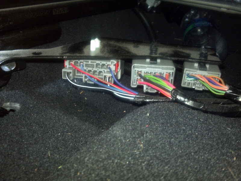
Here is a picture of the connectors under my seat, not sure if they would be the same as yours, but not all of the wires in view (female connectors) are actually being used. It looks like the harness comes in from the TIPM. The male connectors are only pinned on mine for the options I have (power seats) and for the seat belt sensor. The left connector goes to the center console, whereas the center and right ones looks like are only being used for the seats.
I hope this helps.
Click this link to view the wiring diagram demo from tech authority. It is only available for 2010 - 2012. Just use the drop down menus to select your vehicle. On the right side I would look at diagrams 43 - Restraints and 63 - Seats. Dig around in there to see if anything matches up to your setup. As mentioned before, these diagrams may not be completely accurate.
Here is a picture of the connectors under my seat, not sure if they would be the same as yours, but not all of the wires in view (female connectors) are actually being used. It looks like the harness comes in from the TIPM. The male connectors are only pinned on mine for the options I have (power seats) and for the seat belt sensor. The left connector goes to the center console, whereas the center and right ones looks like are only being used for the seats.
I hope this helps.

Thread
Thread Starter
Forum
Replies
Last Post

