Electrical (no speedo, grid heater, volt meter)
#1
Electrical (no speedo, grid heater, volt meter)
New here, and proud new owner of a 1st gen. Sold a 4th gen just to go old school. Hereís the vehicle in question:
ē 1981 Dodge Ram Crew Cab Short Bed ó 1992 Cummins, complete harness, tranny column etc. from donor.
Here is the issues Iím having, that popped up after parking it for the night:
ē Fired up just fine, but noticed water in fuel/wait to start didnít illuminate.
ē drive down road, no speedo
ē.volt meter (normally bounces around 3/4 mark on gage, now fixed at 1/4 mark. (Still pulses when signaling)
Here is what Iíve tried:
ē Check fusible links (with light tester and pinch/pull test
ē Tested alternator
ē Replaced VSS (at tranny)
ē Checked grounds to body and engine
ē Replaced ignition
ē Checked fuses under column
ē Purchased a block relay (for the 3 individual relays mounted to driver inner fender and tested each individual one (no change)
ē Check overall wiring for shorts, tears looseness etc. (including Crank Sensor)
Next thing Iím trying:
ē Ordered the pair of relays that have the threaded studs on top, they should be here in a day or so.
So so I wanted to post this up, one Iím new to learning 1st gen electrical problems, and everyone seems to have their own unique cases, so I figure whatís one more to the cause. I know thereís a lot of knowledge in these forums and experiences. If Iím missing something or someone has a suggestion, please offer. As I divulge this truck, Iíll do my best to contribute to the forum, posting what I can on repairs, updates etc. the truck is nice and rust free from west coast. Itís my daily driver. Thank you!
#2
Registered User
I will be following this thread as I'm having the same problem here, I'm thinking it is the computer.
#3
Registered User
Pray tell why are you buying parts before you diagnose the problem?
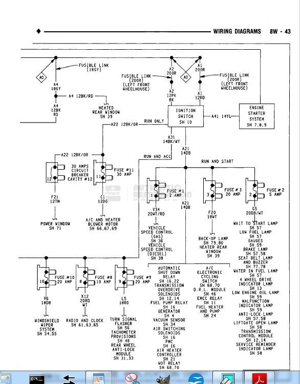
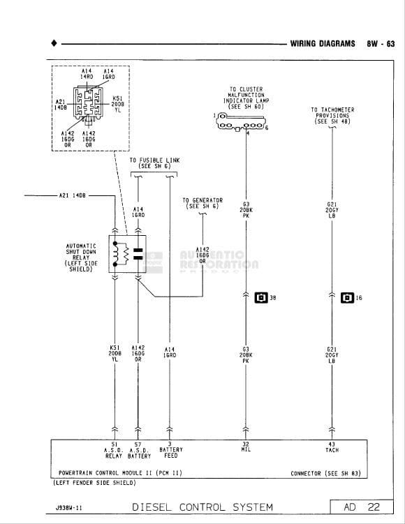
1. The ignition switch provides power to the PCM pin 9. Is it there? -> Ig switch, fuses or wiring.
2. If 1 is OK, PCM powers the ASD relay from pin 51.
3. ASD relay powers PCM through pin 57 (ASD POWER)
Everything else you cite is driven by the PCM.
I've seen this on my truck. Turned out to be a wire nackered at the ASD relay where some poke probed it, didn't seal the wound, and 20 years of salt did it in. Parts cost less than a dollar. Hour or so of time.
You should start by downloading the wiring diagrams in the FAQ's for 1991.5 (same animal)
#4
Registered User
Not to hijack this thread but the reason I figure the computer is about a month ago it started charging at 16+ volts... battery did not get hot, didn't boil' lights didn't seem to be brighter so I figured the comp was just going wonky. Did not drive the truck for a few days and when I did no wait to start light no charge no spedo no overdrive. Changed crank sensor, no change so just figured comp got fried because of over charging.... my bad
#5
Registered User
Electrical is not my forte that being said,
I have tried looking at the diagrams and can't seem to find the one that has the pin diagram on it with the pin numbers
I have tried looking at the diagrams and can't seem to find the one that has the pin diagram on it with the pin numbers

The following users liked this post:
Dstines (04-18-2019)
#6
Well, Iíve been ďdiagnosingĒ best I can. Ran multimeter checks, checked connections, tested alternator etc. had a new ignition (came with truck) so figure why not put it in?
Iím trying to work through cheapest possibilities first. The asd relays were 50 bucks. Iím of the mindset, it doesnít hurt to replace certain things due to age alone.
Regarding ďpinsĒ, does that mean individual wires coming from pcm? Iíve pulled that box off, opened it up, doesnít look ďfriedĒ or anything. Just normal silicone closed circuit. The wires and connections were all good as well. Thanks for responses!
#7
Registered User
Sounds like there's no battery voltage showing up on some of the dark blue circuit from the ignition switch. It goes all over, including voltage regulator, generator, fuel solenoid, transmission and speedo circuits, etc.
Trending Topics
#8
Registered User
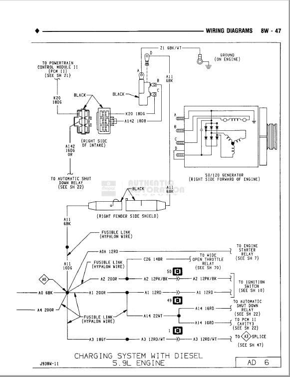
Well I got mine fixed, turns out I did not have constant power to the red wire in the pcm ? connector nor in the red wire on the asd relay, these are constant power wires no key on. These two wires are the ones right next to the ducks foot that are spliced together to a white fusable link coming from the firewall, mine as j_martin said i had a bloom growing out of the splice where someone had probed it..
I trimmed the red wires back till I found clean wire, put battery power to each of them, now I had power to the relay and the pcm so I removed the fusable link replaced it with an in line fuse for now and everything works as it should.
Hats off and a thank you to j_martin for making me think
I trimmed the red wires back till I found clean wire, put battery power to each of them, now I had power to the relay and the pcm so I removed the fusable link replaced it with an in line fuse for now and everything works as it should.
Hats off and a thank you to j_martin for making me think

The following 2 users liked this post by nonrev:
Dstines (04-21-2019),
nothingbutdarts (04-21-2019)
#9
What is the best way of tracing this? From ignition to pcm/battery? Where do these dark blue wires terminate? Do they remain dark blue Throughout?
#10
Registered User
with the key on test the dark blue wire on the plug that goes into your asd relay it should have power, the same with the blue wire in the plug that goes into your pcm.
The red wire on your asd plug and your pcm plug should have power with the key off or on.
My truck did the same as yours turned out I had no power to the red wires in the asd plug nor the pcm plug... fixed that everything works again!
The red wire on your asd plug and your pcm plug should have power with the key off or on.
My truck did the same as yours turned out I had no power to the red wires in the asd plug nor the pcm plug... fixed that everything works again!
#11
Registered User
The service manual, over a thousand pages, is available on CD from Geno's Garage for a very nominal fee. It is priceless when tackling these old machines with the million mile motor, 150k mile bodies, and 30k mile electrical systems.


#12
not intentionally stating the obvious here but there are fusible links at the ignition and column, as well the driver fender? Thanks for the wiring diagrams. And Iíll order that book (itís about 100 bucks from genos). Iíll also try your test norev. Thank you both, much appreciated.
#13
Registered User
not intentionally stating the obvious here but there are fusible links at the ignition and column, as well the driver fender? Thanks for the wiring diagrams. And Iíll order that book (itís about 100 bucks from genos). Iíll also try your test norev. Thank you both, much appreciated.
It also makes it possible to print off pages I'm working with in the shop, get em all greased and wrinkled up, and discard them without remorse.
Stuff that I find I have to skip around in, such as the electrical diagrams, I've printed off and bound for shop work.
The following users liked this post:
nonrev (04-22-2019)
#14
Got my two new relays (top of driver inner fender ones) and while it want be a shock to many of you, that didnít fix anything either. Iíve chased this clump of wires from under steering column, up to inside of firewall, and the went outside of firewall, pulled the big rubber boot off and tested everything from there. My red has constant hot, the larger blue wire is hot with switch on. Other small blues light up as grounds on my tester..... Iím of the mindset at this point to begin deleting this wiring system and pcm. Iíve read of a few guys successfully doing this. Right now, the only thing not working that really bugs me, if the speedo/odometer. Would like to keep track of my oil changes/maintenance. I read that by simply grounding the blue wire at the VSS, that this would allow it to work absent of pcm. Is this true? Iíll attach a link from a source I read who appears to have most of this figured out, absent of cruise control. Painless wiring has a universal system, I wonder if it wouldnít be best to just gut ever and start with that? Here is the link for what this guy did:
Early Cummins powered Dodge computer removal and rewire
Early Cummins powered Dodge computer removal and rewire
#15
Registered User
I read it on the internet. It must be true.
Actually, if you ground the blue wire at the VSS, it'll pretty much take out that whole circuit. BTW, it appears that may be your problem. It's common for that wire to get knackered by the throttle linkage if you aren't careful about where things are routed.
The blue wire at the VSS is a leg of the A21 circuit (keyed power). Certainly grounding it would be trouble, and disconnecting it and grounding the connection it was on would be the equivalent of key off or no battery.
There's a splice in the A21 circuit, I believe under the dash, that might be your problem. Systematic tracing and trouble shooting with the correct diagrams should find the actual fault.
Got my two new relays (top of driver inner fender ones) and while it want be a shock to many of you, that didnít fix anything either. Iíve chased this clump of wires from under steering column, up to inside of firewall, and the went outside of firewall, pulled the big rubber boot off and tested everything from there. My red has constant hot, the larger blue wire is hot with switch on. Other small blues light up as grounds on my tester..... Iím of the mindset at this point to begin deleting this wiring system and pcm. Iíve read of a few guys successfully doing this. Right now, the only thing not working that really bugs me, if the speedo/odometer. Would like to keep track of my oil changes/maintenance. I read that by simply grounding the blue wire at the VSS, that this would allow it to work absent of pcm. Is this true? Iíll attach a link from a source I read who appears to have most of this figured out, absent of cruise control. Painless wiring has a universal system, I wonder if it wouldnít be best to just gut ever and start with that? Here is the link for what this guy did:
Early Cummins powered Dodge computer removal and rewire
Early Cummins powered Dodge computer removal and rewire
The following users liked this post:
nothingbutdarts (04-24-2019)

