
Common Problems and How Do I Articles Needed...


Registered User
Joined: Nov 2007
Posts: 26
Likes: 0
Registered User
Joined: Sep 2006
Posts: 283
Likes: 0
From: Hardinsburg, Indiana
Registered User
Joined: Sep 2006
Posts: 283
Likes: 0
From: Hardinsburg, Indiana
Heres a link to the complete parts lists for any dodge, theres some good stuff here. If you ever need part #'s All Dodge http://www.jameskowalski.com/Dodge/Parts/index.html
1994-1996 Trucks http://www.jameskowalski.com/Dodge/P...996_Trucks.pdf
1994-1996 Trucks http://www.jameskowalski.com/Dodge/P...996_Trucks.pdf
Registered User
Joined: Sep 2004
Posts: 239
Likes: 3
From: hour drive north of Spokane WA
I was looking for how to adjust timing articles and found one that keeps popping up.
http://dodgeram.info/tsb/1994/18-10-94a.htm
this is from http://dodgeram.info/
I just searched and cut/paste links here
http://dodgeram.info/tsb/1994/18-10-94a.htm
this is from http://dodgeram.info/
I just searched and cut/paste links here
Registered User
Joined: Mar 2008
Posts: 24
Likes: 0
From: Seattle WA.
1998.5 12V auto 47RE problems
HERE ARE SOME PICTURES OF A 12 VALVE 47RE WITH OVERDRIVE PROBLEMS AND HOW TO TROUBLESHOOT. GOOD PICTURES OF PARTS.
https://www.dieseltruckresource.com/...98#post2266398
https://www.dieseltruckresource.com/...98#post2266398

Registered User
Joined: Dec 2003
Posts: 14,672
Likes: 9
From: Montana
Returning to Stock Timing
Courtesy of YKDave
Here's a very 'simple' way to set your timing back to stock (or whatever the pump has been set at if it has been rebuilt and the pump timing altered)
First off, bar the engine over to #1 TDC where you will be able to lock in the pump gear timing pin (see pic below). the timing pin is located just below the injection pump.
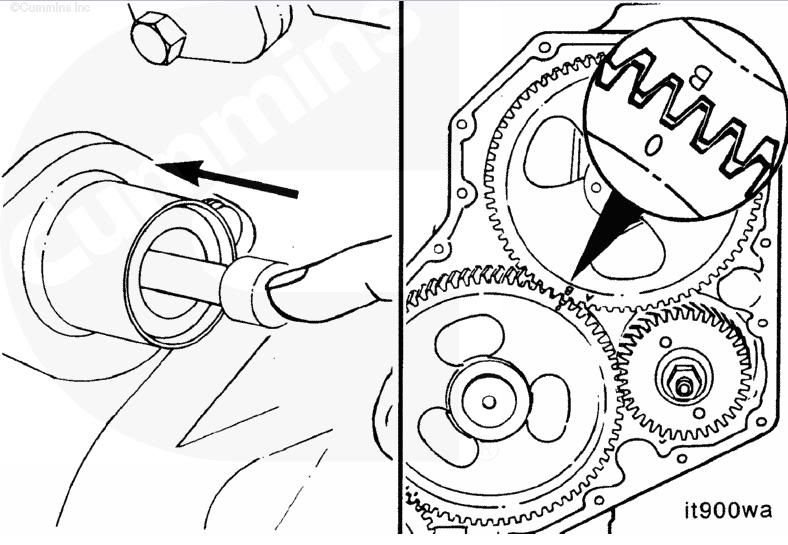
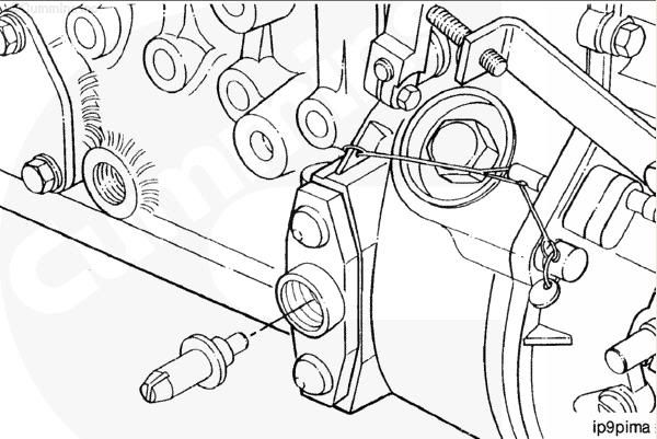
Now, if you are lucky and the timing as not slipped you will be able to pop the plug off of the side of the pump and pull out its 'timing plug', on one end it just has a little metal 'tit' that faces inwards towards the pump for normal operation and on the other end it has a plastic part with a notch cut into it that engages a timing arm inside the pump.
When you pull the plug out of the hole you should be able to see the arm in there and should be able to flip the timing plug over and have it fully insert into the hole and the notch line up on the timing arm. If you cannot see the arm your timing is way out to lunch, if you can see the arm but the timing plug wont go in properly (very close but wont go), the timing has slipped a tad. at that point its your call if you want to reset it or not. (IIRC approx 1mm of movement on the arm = 1.5* timing)
This is the location of the pumps timing plug (basically between the pump and gov housing) and its orientation for normal operation.
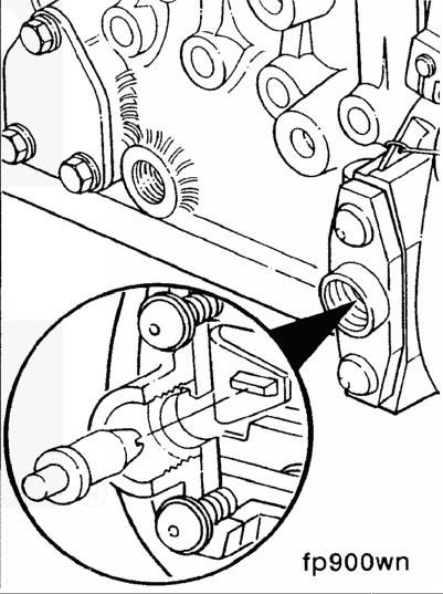
this picture shows the timing plug being flipped around and locking to the notch on the timing arm inside the pump
At this point if you decide to reset the timing, MAKE SURE THE TIMING PIN ON THE GEARTRAIN IS DISENGAGED!
Then while watching through the hole in the side of the pump, bar the engine over till the arm is centred and you can engage the timing plug fully.
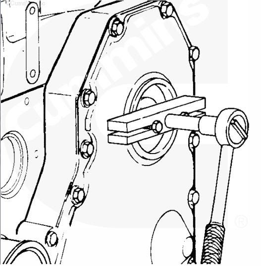
Now, for the sake of not breaking that plastic plug accidentally, remove it. Then proceed to remove the pump drive gear bolt (its tighter than a ****!) and use a puller to remove the gear. you may want to just quickly double check the timing on the pump didn't accidentally move before pulling the gear.
The puller required is a '2 bolt', their are specialty ones sold (i have one), but have been told any puller will do.
Now with the gear loosened from the shaft, get in there with some brake clean or some type of cleaner that LEAVES NO RESIDUE!, this is very important, any bit of gunk or oil on the shaft WILL cause the timing to slip.
Then, bar the engine over till the timing pin will engage in the gear. Now hand tighten the nut onto the pump shaft, disengage both timing pins, and while holding the engine from spinning (hopefully using the proper barring tool!) you can tighten the pump shaft bolt to 145ft/lb
Now, in theory, if you engage the timing pin on the geartrain and pull the plug out of the pump you will be able to see the arm in there and engage that timing plug. As long as nothing moved while you were doing this...
I think that about covers it, i know this topic pops up every once in a while so i hope this helps some of you!
Last but not least.... DO NOT FOGET TO DISENGAGE BOTH TIMING PINS BEFORE MOVING THE ENGINE, YOU WILL BREAK THEM!!!!
Here's a very 'simple' way to set your timing back to stock (or whatever the pump has been set at if it has been rebuilt and the pump timing altered)
First off, bar the engine over to #1 TDC where you will be able to lock in the pump gear timing pin (see pic below). the timing pin is located just below the injection pump.
Now, if you are lucky and the timing as not slipped you will be able to pop the plug off of the side of the pump and pull out its 'timing plug', on one end it just has a little metal 'tit' that faces inwards towards the pump for normal operation and on the other end it has a plastic part with a notch cut into it that engages a timing arm inside the pump.
When you pull the plug out of the hole you should be able to see the arm in there and should be able to flip the timing plug over and have it fully insert into the hole and the notch line up on the timing arm. If you cannot see the arm your timing is way out to lunch, if you can see the arm but the timing plug wont go in properly (very close but wont go), the timing has slipped a tad. at that point its your call if you want to reset it or not. (IIRC approx 1mm of movement on the arm = 1.5* timing)
This is the location of the pumps timing plug (basically between the pump and gov housing) and its orientation for normal operation.
this picture shows the timing plug being flipped around and locking to the notch on the timing arm inside the pump
At this point if you decide to reset the timing, MAKE SURE THE TIMING PIN ON THE GEARTRAIN IS DISENGAGED!
Then while watching through the hole in the side of the pump, bar the engine over till the arm is centred and you can engage the timing plug fully.
Now, for the sake of not breaking that plastic plug accidentally, remove it. Then proceed to remove the pump drive gear bolt (its tighter than a ****!) and use a puller to remove the gear. you may want to just quickly double check the timing on the pump didn't accidentally move before pulling the gear.
The puller required is a '2 bolt', their are specialty ones sold (i have one), but have been told any puller will do.
Now with the gear loosened from the shaft, get in there with some brake clean or some type of cleaner that LEAVES NO RESIDUE!, this is very important, any bit of gunk or oil on the shaft WILL cause the timing to slip.
Then, bar the engine over till the timing pin will engage in the gear. Now hand tighten the nut onto the pump shaft, disengage both timing pins, and while holding the engine from spinning (hopefully using the proper barring tool!) you can tighten the pump shaft bolt to 145ft/lb
Now, in theory, if you engage the timing pin on the geartrain and pull the plug out of the pump you will be able to see the arm in there and engage that timing plug. As long as nothing moved while you were doing this...
I think that about covers it, i know this topic pops up every once in a while so i hope this helps some of you!
Last but not least.... DO NOT FOGET TO DISENGAGE BOTH TIMING PINS BEFORE MOVING THE ENGINE, YOU WILL BREAK THEM!!!!
Registered User

Joined: Jun 2005
Posts: 409
Likes: 19
From: kansas
37337 1-ton wheel cylinders install with pics!
I changed my rear wheel cylinders out yesterday since I had the day off for school. Since I had the camera on hand I snapped some shots to let other members see how easy it since.
I bet there are a few people that have read about these and thought, "that might be too hard for me" when in fact it couldn't be farther from the truth.
You will need atleast the following:
Here they are (angelic music playing softly as I stare at them) Napa 37337 one tone wheel cylinders. They cost 8.97 a piece and like a fine Italian sports car, "Made in Italy"


First, remove wheel, this was easy,but I don't live in the rust belt

Second, remove drum if yours does not come off easily follow Infidels advice:
"once the tires are off and wheels off the ground loosely screw on lug nut back on each side. Start the truck, put it in gear, rev it up and slam on the brakes. Do it in forward and reverse if necessary. You will hear a loud pop when the drums break loose. It's worked every single time for me, I never break out the BFH anymore." From Infidel

Third, you only have to remove the forward spring to get the wheel cylinder out

I didn't get a picture of the removal of the wheel cylinder, pretty easy two 1/2" bolts and she comes right out.
Fourth, compare the two and they are dimensional close


Lastly, reinstall and bleed the system.
Note: your brake warning light may come on after the job is done ie. after the final bleed ( do not let the system go dry or it is a biotch to get the air out of the ABS unit, read: trip to dealer). If the light comes on, unhook both batteries for 10 minutes and problem solved. Pull out into the street and while backing up apply the brakes quick and hard to re-adjust the rear shoes. Enjoy new found braking confidence.
I bet there are a few people that have read about these and thought, "that might be too hard for me" when in fact it couldn't be farther from the truth.
You will need atleast the following:
- 10 mm tubing wrench
- brake tool
- BFH and LFH (big F#$@ing hammer and its smaller counterpart)
- slip pliers
- 3/8" ratchet with 1/2" socket and 3" ext.
Here they are (angelic music playing softly as I stare at them) Napa 37337 one tone wheel cylinders. They cost 8.97 a piece and like a fine Italian sports car, "Made in Italy"
First, remove wheel, this was easy,but I don't live in the rust belt
Second, remove drum if yours does not come off easily follow Infidels advice:
"once the tires are off and wheels off the ground loosely screw on lug nut back on each side. Start the truck, put it in gear, rev it up and slam on the brakes. Do it in forward and reverse if necessary. You will hear a loud pop when the drums break loose. It's worked every single time for me, I never break out the BFH anymore." From Infidel
Third, you only have to remove the forward spring to get the wheel cylinder out
I didn't get a picture of the removal of the wheel cylinder, pretty easy two 1/2" bolts and she comes right out.
Fourth, compare the two and they are dimensional close
Lastly, reinstall and bleed the system.
Note: your brake warning light may come on after the job is done ie. after the final bleed ( do not let the system go dry or it is a biotch to get the air out of the ABS unit, read: trip to dealer). If the light comes on, unhook both batteries for 10 minutes and problem solved. Pull out into the street and while backing up apply the brakes quick and hard to re-adjust the rear shoes. Enjoy new found braking confidence.

Registered User
Joined: Sep 2004
Posts: 2,888
Likes: 1
From: St Paul , MN.
I did not catch if it was mentioned earlier , and also the issue of posting other sites info , but I found that starting with the yr. to yr. changes -info was really good way to start planning .
But this was from the TDR website , buyers guide , listed the changes / mods as I remember , I would hope that good info is shared , but not sure .
If it is OK , I could find my link & post .
Also a local web site here is accumulating the same list , but then again issues between sites are a bummer .
Registered User
Joined: May 2006
Posts: 73
Likes: 0
From: Ohio
Fuel shutoff relay replacement
I finally had to replace my fuel shutoff relay. Rather than paying the dodge dealership $85 for the relay I went to the local big rig supply store. I purchased the 75 amp relay for $12.
As with other after market relays it doesn't match the original one in type on the firewall. To keep it like the original I preformed a little modification.
I took the old relay and gutted the case of it's inner workings. The coil and the contacts were removed with the help of a moto-tool.
The replacement relay should fit inside of the original relay housing. Connect the new replacement to the connector harness and simply slide it into the old casing. The connector will lock into place keeping the new replacement inside the old relay housing.
Next time when the relay needs to be replaced simply release the connector catch from the housing. The previous relay will drop allowing for a new replacement.

Registered User
Joined: Dec 2006
Posts: 1
Likes: 0
From: Portland, Oregon
Starter won't crank the engine
The Problem - Engine won't always crank over
If you find yourself twisting the ignition key to Start and occasionally nothing happens, or mostly nothing happens, then you can be fairly certain the contacts within the Cummins engine's Nippon-Denso starter are burned. By "burned" I mean half gone. This is a common problem with Dodge Diesel Pickups, especially those used for short trips and are started frequently. Don't let the dealer con you into shelling out $500 or more for a new starter or rebuilt starter. There's a better solution and it's cheaper too.
Super Contacts
Denso starters can be repaired in a couple of hours to better-than-new condition using an improved design starter contact set called Super Contacts developed by a guy named LarryB. All model year Dodges diesels use the same repair kit, which can be found at:
http://www.fostertruck.com/dodge/default.htm
I do not exaggerate when I say better-than-new. A repaired Denso starter will perform more start cycles than a brand new one.
The Super Contact kit sells for $39, which to my mind is a bargain. Study the online instructions to see how easy it is to install the upgrade parts. A hardcopy of the same instructions is packed with the contact upgrade kit. The supplied instructions detail most of what needs to be done after the starter is removed from the vehicle. I have a few additional tips to add later in this post. It's more hassle getting the starter off and on than doing the upgrade to the starter contacts
Why do the starter's contacts fail prematurely?
My 1998 12-valve 2500 developed intermittent starter problems at about 45K miles. I drive in the city and make a lot of short trips; It's cold in the winter where I live too; I have friends that live in suburbia and the country that didn't have trouble until 80k miles.
But why? Starting a Dodge Cummins diesel engine demands a surge of DC current through the starter contacts of about the same number of amps as a heavy duty welding machine passes through the welding rod welding heavy steel plate. Cold starting temperatures significantly increase the starting current demand. With each start cycle, a little of one of the contacts is eaten away (that's right, just the starter-motor side; the battery side contact is almost like new.) and a little piece of the the solenoid ring contact burns away. Eventually half the thickness of the starter-motor side contact is eroded away and the ring contact is pock-marked. At his point the ring contact barely reaches the eroded starter motor side contact; failure to crank is the result.
The difference between a factory contact and a Super Contact is obvious when you hold the parts in your hand; a Super Contact is more than twice as wide, so it has more than twice the contact surface area. Super Contacts are thicker too, so resistive and arc heating are more readily dissipated. Both the battery side (line) and the motor side (load) contacts are identical and interchangeable. Because the contacts are damaged by heating, and heating is caused by I-squared-R losses, Super Contacts will last not twice as long, but four times as long as Denso factory contacts.
Installing Super Contacts
1. Safety first! Read the online instructions and ask yourself if you are comfortable removing the starter from the engine. If you aren't, then have your favorite repair shop do the work. [I]The toughest part of the whole job is removing and replacing the starter on the engine.[I]
2. Order the Super Contact kit.
3. Gather the tools and supplies you'll need. I suggest: a trouble light, an inspection mirror, 3/8" socket set (including extensions), a 10mm 12-point (not 6-point!)socket, an 8" Crescent wrench, 3/8" torque wrench, several clean shop rags, a tube of LocTite #242 or #243 thread locking fluid, Noco #2 Battery Cable Treatment, and a full spray can of either CRC brand Brakleen or CRC Lectra-Motive Electric Parts Cleaner. These supplies can be had from any auto parts store.
4. Park the truck in a safe and level place to work, set the brakes and chock the wheels. I have a 2500 4x4 and did not need to jack up the front end to get crawl clearance to reach the starter. You may need a jack and stands.
5. Disconnect both batteries negative terminals. Put a heavy plastic bag over both negative terminals to insulate them. This will protect you against one of the loose terminals accidentally flopping back against either battery post. Check the dome light to make sure the power is off.
6. If you have the Dodge Service Manual, look up Starter. In my 1998 manual it's on pages 8B-9 through 8B-10. The starter is on the driver's side of the engine. Find the starter on your vehicle. Two wires and three bolts must be removed to free the starter.
Using the trouble light and inspection mirror, locate the large red power lead and rubber boot. Fold the rubber boot back to reveal the terminal post and nut. Use the Cresent wrench to remove the nut, then slip cable lug off the starter terminal post and push the cable out of the way. Put the nut and washer (if present) aside in a safe place. Now locate the solenoid wire; it's much smaller. Remove the nut/washer and put them aside.
Three unusual 12-point bolts hold the starter to the bell housing. Put a 10mm 12-point socket on your ratchet and remove the bottom bolt. Put on an 8" or 10" extension or two extensions back to back to get enough reach to get on the top two bolts. You will need the inspection mirror to see these bolts. This is the toughest part of the removal job. Remove one these bolts, then carefully remove the other while supporting the starter. Don't trust the starter to hang on the bell housing. Remove the starter from the engine.
7. Clean off the starter outsides well with degreaser or Brakleen.
8. Follow the disassembly instructions provided with the Super Contacts. After "Remove exterior nuts from contact lugs.", get the Brakleen or Lectra-Motive spray can. Holding the starter gear end up, spray the inside of the contact housing and the solenoid well to flush away all the soot and bits of burned copper. Keep the gear end up and the contact housing pointed down so all the debris flushed free runs out. Inspect the inside of the contact housing for any melted copper bits still stuck to the walls or contact blocks, then pick off any remaining copper bits. Save the removed solenoid if the copper ring contact is not badly pitted or burned. Recycle the copper factory contacts.
9. Begin to reassemble the starter by going to the next Super Contact instruction "Reinstall New Contacts and new plunger". Complete the Super Contact instructions.
10. Reinstall the starter in the bell housing. Like removing it, this is a tougher job. I get the starter in place and screw in the bottom bolt to hold the starter in place. Now apply LocTite to the first upper bolt and hold it in place with the extension while wiggling the start around until the bolt drops into the hole in the bell housing. Run the bolt in just short of snug. Apply LocTite to the second bolt and install it snug. Remove the bottom bolt and apply LocTite, then reinstall it. Use the inspection mirror to verify the starter's flange is seated completely against the bell housing. When satisfied it's flush, snug up the bolts starting with the top-most. Next, using the torque wrench and extensions, tighten the bolts to 32 ft-ibs (43 Newton-Meters) torque.
In which order is easiest, reattach the solenoid wire and nut/washer, and reattach the heavy red power cable terminal and nut (and washer if present). Torque the heavy cable nut to 120 inch-lbs (14 Newton-Meters). In practice, it's difficult to get a bulky torque wrench on the power terminal nut where clearance is so tight. I tighten mine to fully snug, plus 1/3 turn. Pull the rubber hood back over the red power cable terminal and nut. Inspect the job.
11. If everything looks good in the final inspection, it's time to reattach the batteries. If you don't already, treat all battery posts and terminals with Noco #2 Battery Cable Treatment spray.
12. That's it! You should not have to deal with the starter contacts for 120K+ miles. Extra long-life tip: Should you need to remove starter again for any reason in the next 80K-120K miles, open the contact housing and clean with Lectra-Motive spray. Remove and reinstall the Super Contacts, swapping like-new battery side (line) contact to the worn motor side (load) contact.
Should you ever need a single replacement Super Contact or a new Denso solenoid slide with contact ring, Larry Buck has a website at: http://www.startercontacts.com

Registered User

Joined: Mar 2009
Posts: 389
Likes: 41
Second Gear Apply Lever Repair
You lost second gear and you are ubber ****** because you have to pull the tranny to replace a broken apply lever. Take a deep breath and relax. There is an easy fix. You need a drill, some bits and a 6mm allen wrench. I used a 7/8" bit but started with smaller bits as a pilot to make drilling easier. Look at the pic for the location to drill. Don't let the bit rip a hole in your converter. The 6mm hex allen wrench will fit into the 1/4" 4 point plug and give you the ability to make less than 1/4 turn at a time. Work the plug out. Drop the pan and replace the lever and adjust the bands. Put the pan back on. Apply some silicone to the plug threads and work it back into the threads with the allen wrench and tighten. Add fluid and you are golden. All in all it took me less than half an hour.
BTW Ask a local trans guy if they have any transmission cores laying around and that you want a 2nd gear apply lever. They will most likely give it to you. Take a 1/4 drive socket wrench, extension and needle nose pliers. Give them a 5 spot for their trouble. The stock one is 3.8. You can also use a 4.2 or a 5. Stay away from lower than 3.8. This number in the force multiplier. It is stamped on the side of the lever. In other words if the piston applies 100 pounds pressure the lever applies 100*3.8=380 pounds pressure to the band. If you go to a higher number it may take slightly longer to apply as it has to travel more. It will however hold tighter. The levers are the same in most Dodge transmissions. You can get one out of any Torqueflight, 518, 46rh,46re, 47rh, 47re etc...
BTW Ask a local trans guy if they have any transmission cores laying around and that you want a 2nd gear apply lever. They will most likely give it to you. Take a 1/4 drive socket wrench, extension and needle nose pliers. Give them a 5 spot for their trouble. The stock one is 3.8. You can also use a 4.2 or a 5. Stay away from lower than 3.8. This number in the force multiplier. It is stamped on the side of the lever. In other words if the piston applies 100 pounds pressure the lever applies 100*3.8=380 pounds pressure to the band. If you go to a higher number it may take slightly longer to apply as it has to travel more. It will however hold tighter. The levers are the same in most Dodge transmissions. You can get one out of any Torqueflight, 518, 46rh,46re, 47rh, 47re etc...
Registered User
Joined: Nov 2010
Posts: 617
Likes: 0
From: Seymour Tn
here is a great thread on GSK's and installing them
https://www.dieseltruckresource.com/...&highlight=GSK
https://www.dieseltruckresource.com/...&highlight=GSK
Registered User
Joined: Jan 2007
Posts: 115
Likes: 0
From: Central Illinois
Drop valve method to get TDC
- Get the engine to compression stroke (both exhaust and intake valves closed) on #1, but before the estimated TDC,
- position a dial indicator on exhaust valve spring after removing all lash,
- tighten exhaust valve to .100 past zero lash,
- bar engine CW EASY till stops on exhaust valve and shows .002-.003 deflection,
- mark dampner clearly near reference point such as sensor,
- back exhaust valve lash off to zero or more,
- bar engine CW past estimated TDC,
- tighten exhaust valve to .100 past zero lash again,
- bar engine CCW EASY till stops on exhaust valve and shows same deflection as before .002-.003,
- mark dampner clearly at the same reference point,
- back off and reset exhaust valve lash to specs,
- mark dampner exactly between two previous marks = TDC,
- bar engine CCW well past TDC and then back CW to the new TDC mark to remove any gear lash