Leece Neville Alternator on a 6BT Cummins
 07-12-2009, 06:47 AM
#1
Administrator
Thread Starter

Part-1
How to Install a Leece Neville Alternator on a 6BT Cummins
First as not to confuse you I have used the pictures from the install of the 140-amp and then the upgrade to the 160-amp units.
With all of the discussions lately on how to replace your factory 120-amp Nippondenso alternator with a Leece Neville 110-555JHO 160-amp Heavy Duty Alternator I will show you step by step how to do the conversion.
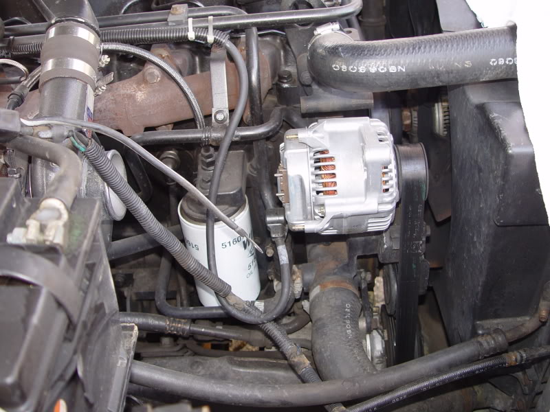
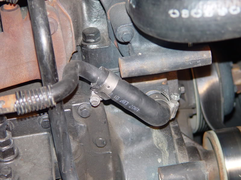
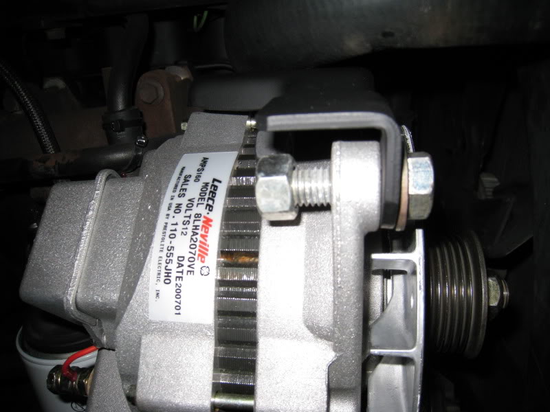
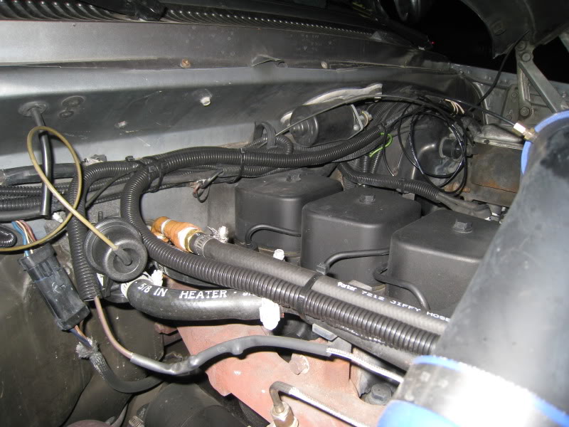
Here you see the side of my 1991 non-intercooled 6BT engine, I have already upgraded the wiring as to extract every last possible amp out it by installing #4 welding cable from the alternator to the battery AND ground but with all of the high powered work lighting and the use of an onboard inverter that can draw up to 100-amps by itself I was poorly underpowered.
I need to be able to idle my engine and charge my battery banks and have enough reserve current to power my inverter.
With the 110-555JHO this was easly accomplished since it is capable of a rock solid 14.2 volts at 100-amps at an IDLE (2000 shaft RPM)
http://www.prestolite.com/literature...31_110-555.pdf
http://www.prestolite.com/pgs_produc...tem=8LHA2070VE
There is also a 110-555HD that has a low speed current of 90-amps except it is only rated at 140-amperes, there are probably hundreds of thousands of these on the road and can be found in most any older Class-8 tractor
http://www.prestolite.com/pgs_produc...tem=8LHA2070VB
Here is the Home website if you would like to browse.
http://www.prestolite.com/
So here we are looking at my engine again, an intercooled engine is going to have a bit more in the way but the alternator is tucked tight against the engine so it should not create and interference with the intercooler plumbing, but this I am not 100% positive.
Start by first disconnecting your battery.
Then remove your factory alternator from its mount by disconnecting the wiring harness and then unplug it from the connector about 12� down towards the fender, removing the top bracket and then the bottom through bolt and put it safely into storage.
Next you can either drain your coolant or have a big pan under the passenger side to catch what small amount will leak out as the hoses are removed.
If you have an automatic transmission you will have a heat exchanger with coolant lines that will need to be relocated.
If you have a manual transmission then you will not have a Heat Exchanger and this will not apply, please move on to the next section.
Remove the bracket that holds the coolant pipe to the exhaust manifold and store it away with the alternator.
At this time you can loosen the hose clamp on the pipe to heat exchanger section of hose and on the right side of the pipe and remove it you can unclamp and remove the short elbow to the side of the block and store it away with the other removed parts.
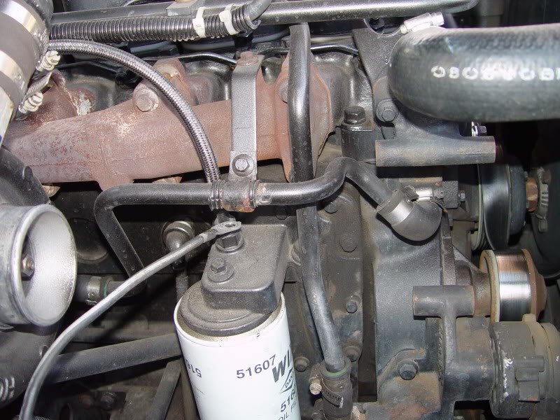
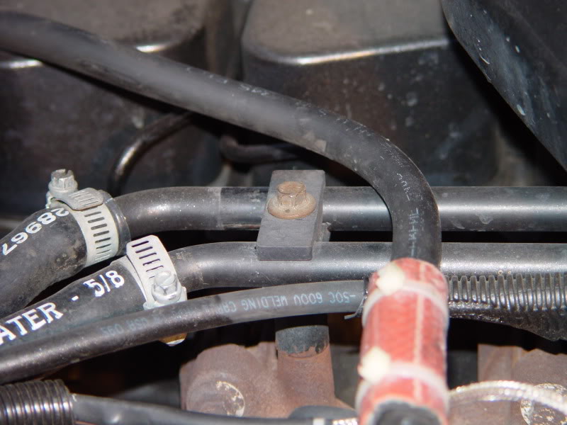
Now loosen the 2) 10mm bolts that secure the support blocks for the 2 metal heater lines and then on the line closest to the valve covers loosen the hose clamp and then you need to slide the entire pipe rearward to the firewall about 1� as you can see by the marks, this will give the needed clearance between the rear of the alternator and the vertical part of the pipe, and then retighten the hose clamp, you might need to cut off about 1� from the hose as to keep a nice arc to the hoses.
Note, if there is a green or colored liner to these hoses do not remove or throw them away, these are silicone hoses and are considered Lifetime and cost about $6.00 per foot.
Now to where you removed the short elbow you will install the new (dayco #80400) bypass hose after you cut the long leg to about 4� you want this hose to be as close to the block as possible so you can carefully trim the short end to make it a tight fit BUT do not cut off too much.
And then angle it up as I did in the picture, install the clamps with the screws in the position that I have them but do not tighten them yet.
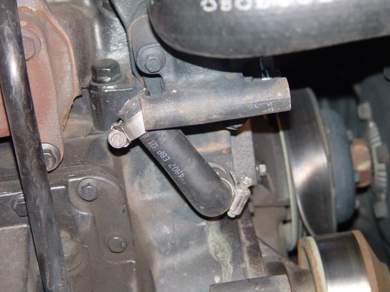
Now insert the long side of the pipe into the 4� section of the Bypass Hose to about where I have it and look and see how the opposite end lines up with the inlet of the heat exchanger and you will see that because of the new added height it will not be at the proper angle so you will need to very carefully massage and bend the radius of the pipe until they line up with the heat exchanger and then once you have them straight you can go ahead and reconnect it to the hose.
Lift it as high and move it as rearward as you can go and not have the 2 pipes rubbing on each other and then secure the clamps.
As you can see in later pictures I sliced a section of 5/8 heater hose and slipped it over the hose as to be between both pipes and then secured it with a TyWrap
Now comes the alternator, the factory Nippondenso alternator has a 2� spacing between the mounting ears while the 110-555JHO has a an industry standard J-180 Mount which is just under 4� or 3.935 to be exact and is also drilled for a � � through bolt so we will need to cut some bushings to adapt it to the 3/8� through bolt we will be using.
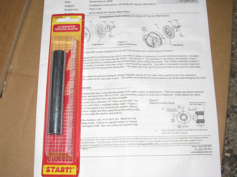
You will need to purchase some spacers; I found this Alternator Sleeve Bushing START P.N. #72075 was the right size being it is 4� long x 3/8� ID
And you will also need a bushing that is 3/8�ID x �� OD that is at least 2� long. (Sorry that I did not show this before I cut it)
In my first install I used some Bronze oilite bushings only because I had them but later replaced them with steel bushings.
With the110-555 JHO alternator on a bench slip the �� OD bushings through the ears and make a mark and them cut them off squarely so they are flush with the respective ear and dress the edge so they are square.
Then cut the 4� long spacer down to just under 2� making sure the ends are square.
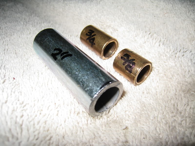
So you should have 3 spacers:
1 @ 2�
1 @ ��
1 @5/8�
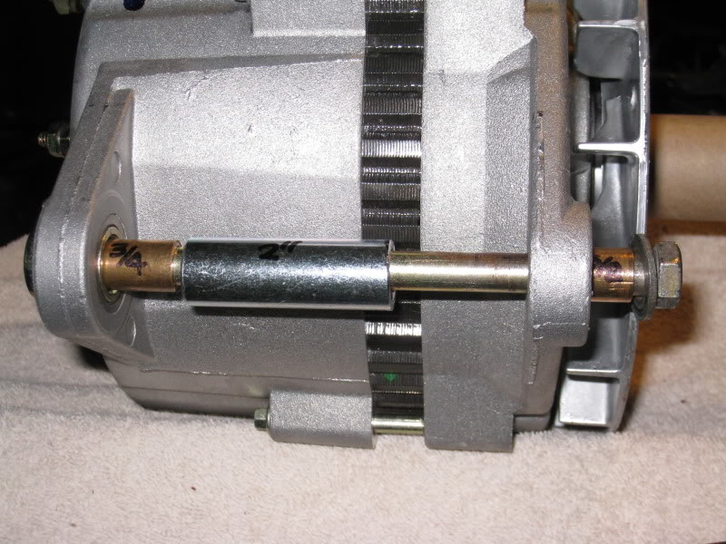
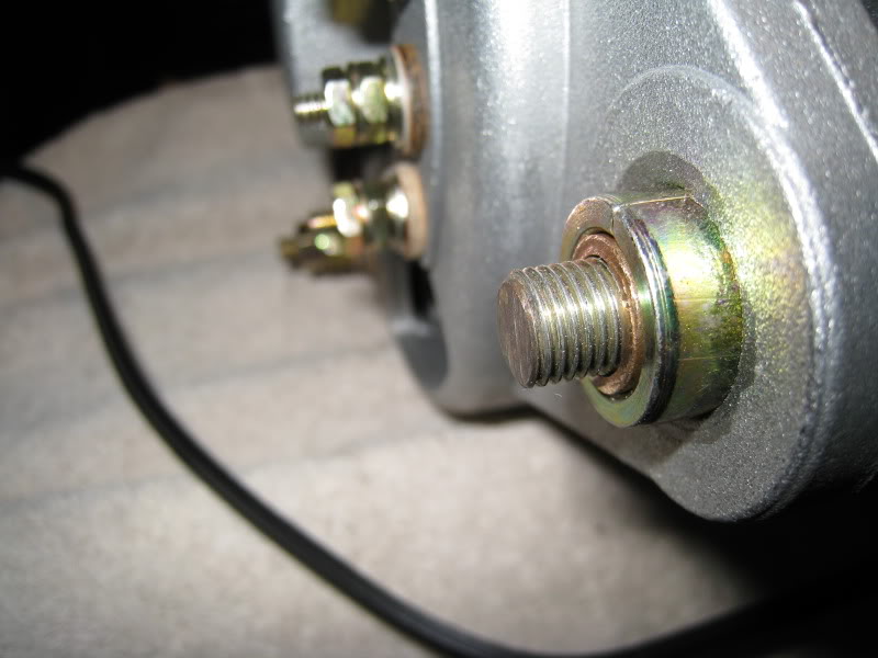
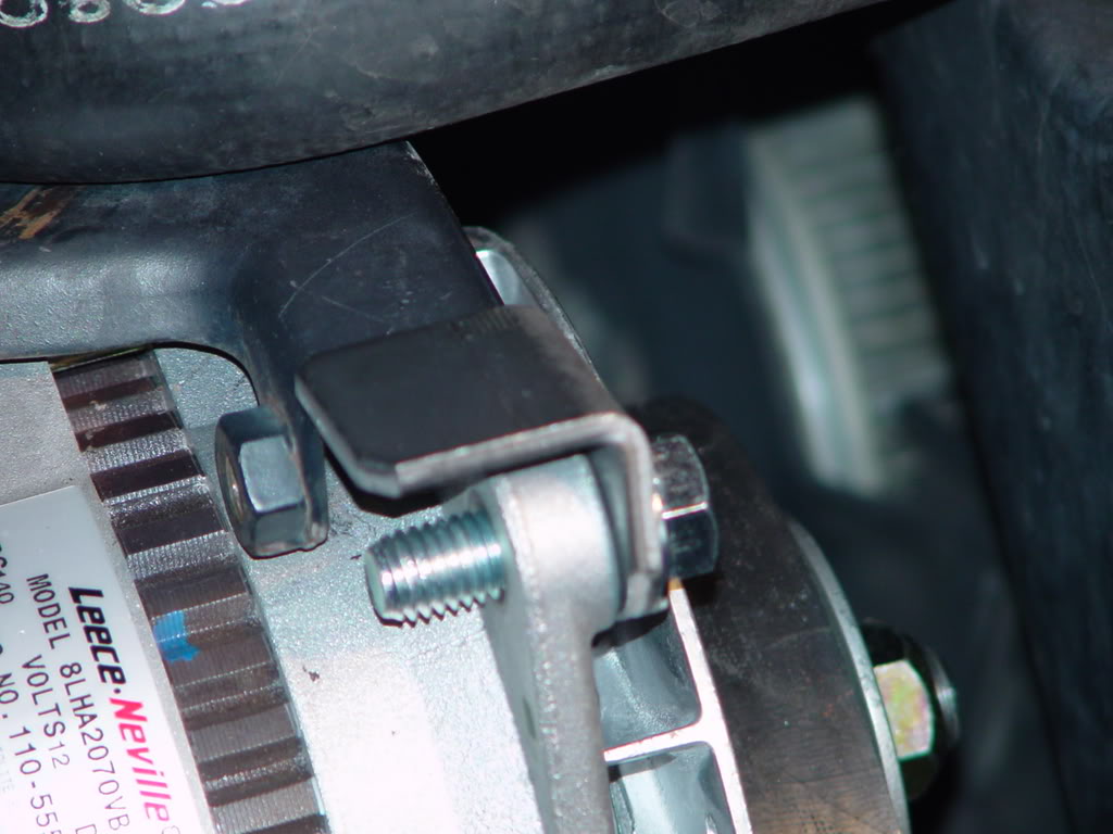
Next insert the bushings into the ears and then take your 3/8 x 6 NF Grade-8 bolt add a washer and slip it through the ears through the bushings and holding it snuggly at the rear you will want to slip on the washer and then hold the nut and see how many threads you will need to just be flush with the end of the nut then mark it with a Sharpie.
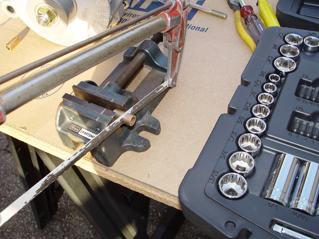
Remove the bolt and thread on the not past the mark to the about �� and then with the bolt in a vise carefully cut off the remaining bolt past the mark and then with a file or Die Grinder dress the end square then unscrew the nut and clean up any threads so the nut fits with ease.
This step needs to be done so the end of the bolt does not rub against the coolant pipe and wear a hole in it.
This is how much of the bolt should protrude past the rear bushing.
How to Install a Leece Neville Alternator on a 6BT Cummins
First as not to confuse you I have used the pictures from the install of the 140-amp and then the upgrade to the 160-amp units.
With all of the discussions lately on how to replace your factory 120-amp Nippondenso alternator with a Leece Neville 110-555JHO 160-amp Heavy Duty Alternator I will show you step by step how to do the conversion.
Here you see the side of my 1991 non-intercooled 6BT engine, I have already upgraded the wiring as to extract every last possible amp out it by installing #4 welding cable from the alternator to the battery AND ground but with all of the high powered work lighting and the use of an onboard inverter that can draw up to 100-amps by itself I was poorly underpowered.
I need to be able to idle my engine and charge my battery banks and have enough reserve current to power my inverter.
With the 110-555JHO this was easly accomplished since it is capable of a rock solid 14.2 volts at 100-amps at an IDLE (2000 shaft RPM)
http://www.prestolite.com/literature...31_110-555.pdf
http://www.prestolite.com/pgs_produc...tem=8LHA2070VE
There is also a 110-555HD that has a low speed current of 90-amps except it is only rated at 140-amperes, there are probably hundreds of thousands of these on the road and can be found in most any older Class-8 tractor
http://www.prestolite.com/pgs_produc...tem=8LHA2070VB
Here is the Home website if you would like to browse.
http://www.prestolite.com/
So here we are looking at my engine again, an intercooled engine is going to have a bit more in the way but the alternator is tucked tight against the engine so it should not create and interference with the intercooler plumbing, but this I am not 100% positive.
Start by first disconnecting your battery.
Then remove your factory alternator from its mount by disconnecting the wiring harness and then unplug it from the connector about 12� down towards the fender, removing the top bracket and then the bottom through bolt and put it safely into storage.
Next you can either drain your coolant or have a big pan under the passenger side to catch what small amount will leak out as the hoses are removed.
If you have an automatic transmission you will have a heat exchanger with coolant lines that will need to be relocated.
If you have a manual transmission then you will not have a Heat Exchanger and this will not apply, please move on to the next section.
Remove the bracket that holds the coolant pipe to the exhaust manifold and store it away with the alternator.
At this time you can loosen the hose clamp on the pipe to heat exchanger section of hose and on the right side of the pipe and remove it you can unclamp and remove the short elbow to the side of the block and store it away with the other removed parts.
Now loosen the 2) 10mm bolts that secure the support blocks for the 2 metal heater lines and then on the line closest to the valve covers loosen the hose clamp and then you need to slide the entire pipe rearward to the firewall about 1� as you can see by the marks, this will give the needed clearance between the rear of the alternator and the vertical part of the pipe, and then retighten the hose clamp, you might need to cut off about 1� from the hose as to keep a nice arc to the hoses.
Note, if there is a green or colored liner to these hoses do not remove or throw them away, these are silicone hoses and are considered Lifetime and cost about $6.00 per foot.
Now to where you removed the short elbow you will install the new (dayco #80400) bypass hose after you cut the long leg to about 4� you want this hose to be as close to the block as possible so you can carefully trim the short end to make it a tight fit BUT do not cut off too much.
And then angle it up as I did in the picture, install the clamps with the screws in the position that I have them but do not tighten them yet.
Now insert the long side of the pipe into the 4� section of the Bypass Hose to about where I have it and look and see how the opposite end lines up with the inlet of the heat exchanger and you will see that because of the new added height it will not be at the proper angle so you will need to very carefully massage and bend the radius of the pipe until they line up with the heat exchanger and then once you have them straight you can go ahead and reconnect it to the hose.
Lift it as high and move it as rearward as you can go and not have the 2 pipes rubbing on each other and then secure the clamps.
As you can see in later pictures I sliced a section of 5/8 heater hose and slipped it over the hose as to be between both pipes and then secured it with a TyWrap
Now comes the alternator, the factory Nippondenso alternator has a 2� spacing between the mounting ears while the 110-555JHO has a an industry standard J-180 Mount which is just under 4� or 3.935 to be exact and is also drilled for a � � through bolt so we will need to cut some bushings to adapt it to the 3/8� through bolt we will be using.
You will need to purchase some spacers; I found this Alternator Sleeve Bushing START P.N. #72075 was the right size being it is 4� long x 3/8� ID
And you will also need a bushing that is 3/8�ID x �� OD that is at least 2� long. (Sorry that I did not show this before I cut it)
In my first install I used some Bronze oilite bushings only because I had them but later replaced them with steel bushings.
With the110-555 JHO alternator on a bench slip the �� OD bushings through the ears and make a mark and them cut them off squarely so they are flush with the respective ear and dress the edge so they are square.
Then cut the 4� long spacer down to just under 2� making sure the ends are square.
So you should have 3 spacers:
1 @ 2�
1 @ ��
1 @5/8�
Next insert the bushings into the ears and then take your 3/8 x 6 NF Grade-8 bolt add a washer and slip it through the ears through the bushings and holding it snuggly at the rear you will want to slip on the washer and then hold the nut and see how many threads you will need to just be flush with the end of the nut then mark it with a Sharpie.
Remove the bolt and thread on the not past the mark to the about �� and then with the bolt in a vise carefully cut off the remaining bolt past the mark and then with a file or Die Grinder dress the end square then unscrew the nut and clean up any threads so the nut fits with ease.
This step needs to be done so the end of the bolt does not rub against the coolant pipe and wear a hole in it.
This is how much of the bolt should protrude past the rear bushing.
 07-12-2009, 06:50 AM
#2
Administrator
Thread Starter
Part-2
You will need an 8 Groove serpentine pulley. The pulley part number is a generic rebuilder number #1269P
This must be modified so the proper alignment can be retained so to do this you must machine the stepped portion off the back of the pulley with a lathe to have an overall width of 1.350�.
You might be able to cut the back of the pulley flush using a sawzall with a fine blade while securing the pulley in a vise but I would prefer you took it to a machines shop.
I took mine to a friend�s Machine Shop and I paid him $20.00 for the 10 minuets it took for him to set it up and machine it.
Again sorry that I do not have pictures of the backside of the pulley.
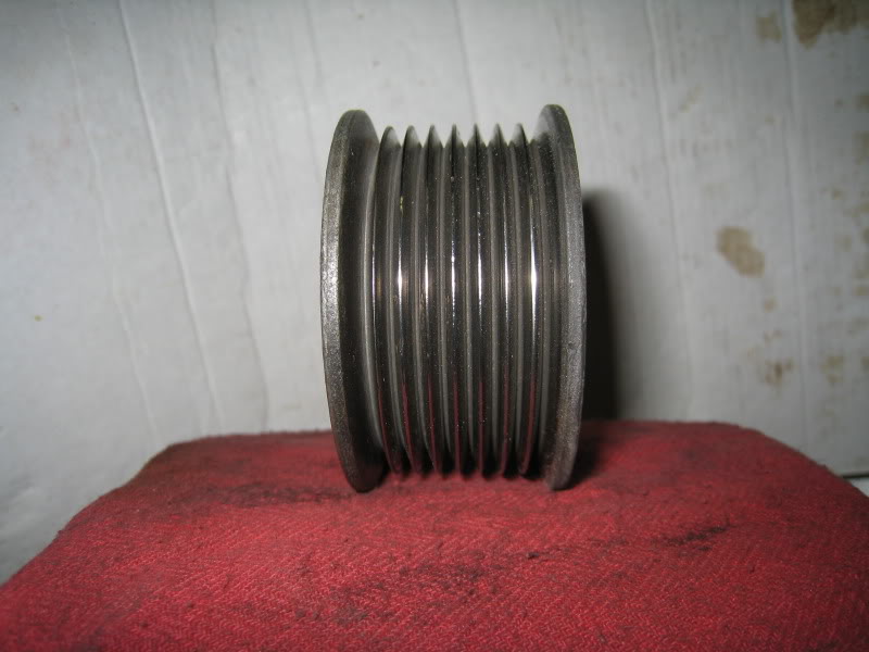
Here is the front side of the pulley; you will notice that it is not cut for a keyway.
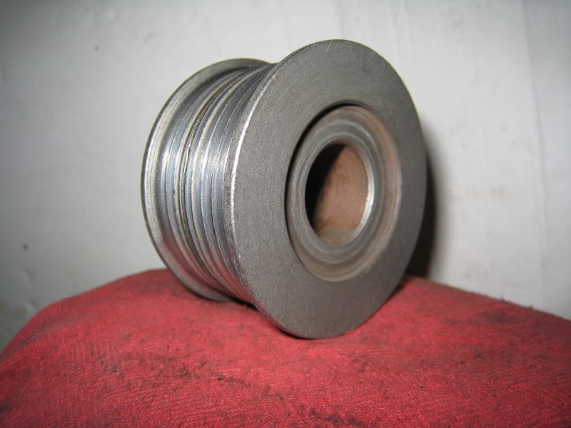
To install the pulley onto the alternator first you need to remove the fan and make certain there is a spacer behind the fan and the recess of the front bearing, if you are replacing the pulley off a working alternator you can omit this check.
Ok so you first need to remove the woodruff key from the shaft and then slip on the new pulley up flat against the fan.
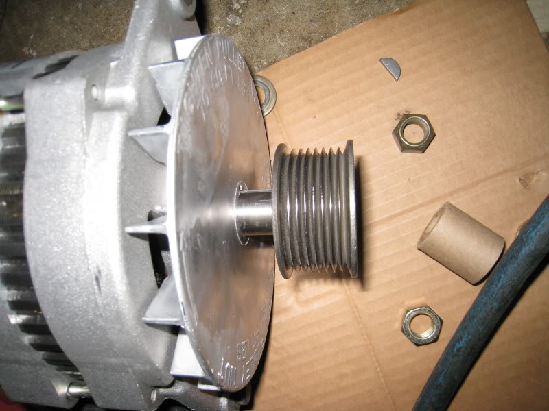
Next install the flat washer and then the locking nut as far as you can by hand then finish tightening it on using an impact wrench, but don�t over do it just make it tight.
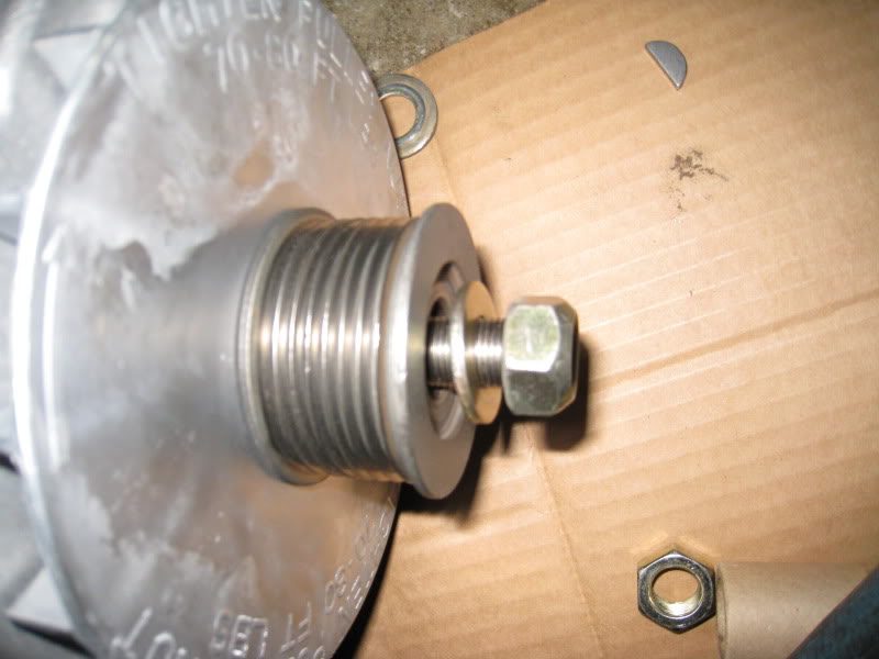
The alternator is now finished and is ready to be installed.
Here is a comparison between the 120-amp Nippondenso alternator and the new 110-555 JHO (J=ISO J-180 Mount HO= High Output) Leece Neville alternator.
At this time I would take some silicone and secure the 2 small bushings inside their respective ears so you so you do not have to worry where they went as you are installing it on the engine.
You don�t have to but it just makes it a bit easier.
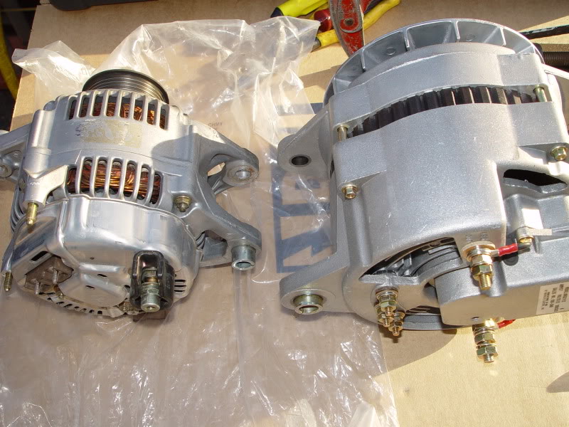
And a front view, if you were to open the hood on any Class-8 tractor somewhere you would find some variant of this alternator inside.
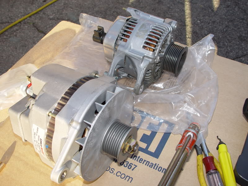
It is now ready to be installed onto the side of the engine so lets get it into a comfortable working position.
Collect up all of your hardware to include the 2� cut spacer, the cut down 6�x3/8 NF Grade-8 bolt, 2 3/8 machine washers, and the 3/8 NF Grade-8 nut, if you were so inclined to do so you could use a Nylock nut here.
Tip: When you choose a washer get yourself a Machine Washer and not a common Cut Washer, a Machine Washer has a smaller outside diameter that is just a bit larger then the head of the bolt and it is also a Grade-8 hardness.
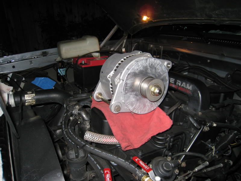
Working from the passenger side after you covered the fender with a protective towel, lower the alternator into position and place the front ear to the front of the alternator mount and then from the radiator side insert the bolt with a washer through the ear with the bushing and into the mount and stop just short of protruding through the mount (this will make the alternator easier to handle) as you move the alternator towards the rear of the engine you need to install the spacer and then slip the bolt through it and out the rear of the mount.
Insert the washer and then finish it off with the nut.
Tip: If the spacer does not fit you might need to slip the adjusting bushing a bit rearward in the ear to gain a bit of room.
Now that the alternator is mounted you will need to snug up the through bolt and then swing the housing up against the side of the engine, by snugging up the nut the alternator should stay in place.
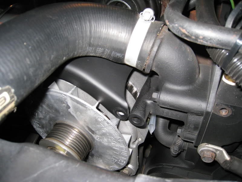
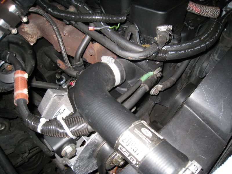
At this time you might want to check for any interference between the case and any coolant lines and adjust them as necessary.
Also see how I protected the coolant pipe by slipping a piece of heater hose over the vertical pipe and securing it. I would recommend you do the same.
You will need an 8 Groove serpentine pulley. The pulley part number is a generic rebuilder number #1269P
This must be modified so the proper alignment can be retained so to do this you must machine the stepped portion off the back of the pulley with a lathe to have an overall width of 1.350�.
You might be able to cut the back of the pulley flush using a sawzall with a fine blade while securing the pulley in a vise but I would prefer you took it to a machines shop.
I took mine to a friend�s Machine Shop and I paid him $20.00 for the 10 minuets it took for him to set it up and machine it.
Again sorry that I do not have pictures of the backside of the pulley.
Here is the front side of the pulley; you will notice that it is not cut for a keyway.
To install the pulley onto the alternator first you need to remove the fan and make certain there is a spacer behind the fan and the recess of the front bearing, if you are replacing the pulley off a working alternator you can omit this check.
Ok so you first need to remove the woodruff key from the shaft and then slip on the new pulley up flat against the fan.
Next install the flat washer and then the locking nut as far as you can by hand then finish tightening it on using an impact wrench, but don�t over do it just make it tight.
The alternator is now finished and is ready to be installed.
Here is a comparison between the 120-amp Nippondenso alternator and the new 110-555 JHO (J=ISO J-180 Mount HO= High Output) Leece Neville alternator.
At this time I would take some silicone and secure the 2 small bushings inside their respective ears so you so you do not have to worry where they went as you are installing it on the engine.
You don�t have to but it just makes it a bit easier.
And a front view, if you were to open the hood on any Class-8 tractor somewhere you would find some variant of this alternator inside.
It is now ready to be installed onto the side of the engine so lets get it into a comfortable working position.
Collect up all of your hardware to include the 2� cut spacer, the cut down 6�x3/8 NF Grade-8 bolt, 2 3/8 machine washers, and the 3/8 NF Grade-8 nut, if you were so inclined to do so you could use a Nylock nut here.
Tip: When you choose a washer get yourself a Machine Washer and not a common Cut Washer, a Machine Washer has a smaller outside diameter that is just a bit larger then the head of the bolt and it is also a Grade-8 hardness.
Working from the passenger side after you covered the fender with a protective towel, lower the alternator into position and place the front ear to the front of the alternator mount and then from the radiator side insert the bolt with a washer through the ear with the bushing and into the mount and stop just short of protruding through the mount (this will make the alternator easier to handle) as you move the alternator towards the rear of the engine you need to install the spacer and then slip the bolt through it and out the rear of the mount.
Insert the washer and then finish it off with the nut.
Tip: If the spacer does not fit you might need to slip the adjusting bushing a bit rearward in the ear to gain a bit of room.
Now that the alternator is mounted you will need to snug up the through bolt and then swing the housing up against the side of the engine, by snugging up the nut the alternator should stay in place.
At this time you might want to check for any interference between the case and any coolant lines and adjust them as necessary.
Also see how I protected the coolant pipe by slipping a piece of heater hose over the vertical pipe and securing it. I would recommend you do the same.
07-12-2009, 06:52 AM
#3
Administrator
Thread Starter
Part-3
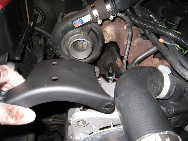
Now we need to temporarily install the upper alternator bracket into place, install the through bolt and snug it up and then pull the alternator up against the side of the engine.
Then to secure the alternator I installed a metal tab that is 1 �� x 1 �� x 3/16� thick that is drilled to accept the ��-13 UNC bolt.
You can make one by taking a piece of 3/6� flat stock 1 �� wide x 3� long and first drill a 1/2� hole 1/2� from the edge, radius the end with the hole in it and then bend it up at 90* to make the bracket
Note: Please PM me if you have any questions as to where you can obtain this ready-formed bracket.
Then I inserted the ��-13 UNC bolt and washer through the bracket and secured it into the top mount of the alternator.
I then positioned the alternator so the end of the bracket is past the hole for the factory bolt and then after I angled the bracket down flush with the top edge of the top mount I then marked it with a scribe.
I then clamped the bracket with a pair of vice grips and then removed the entire top bracket and the tab then using my wire feed welder I tacked the edge of the tab to the bracket to hold it while I adjusted it.
With the tab tacked I reinstalled the top bracket to the engine and reinstalled the ��-13 UNC bolt and washer to the alternator, with the one side tacked it was easy to move it into position to its final position; after it was where I wanted it I again removed the bracket and finished welding the tab.
The reason that I installed the new mounting tab on the outside of the hole was this way if I ever wanted or needed to reinstall the factory Nippondenso alternator the entire conversion could be reversed and be back to factory within about 10 minuets time.
After I was sure of the fit I removed the bracket and after a quick deburring and washing it down with lacquer thinner I gave it a quick coat of paint and let it dry.
Then I installed it onto the engine.
Before I positioned the bracket onto the top mount I inserted a piece of polyurethane between the side of the alternator case and the side of the bypass hose to protect the hose from rubbing against the side of the rough case then I aligned the bracket and insert the long through bolt.
Do not tighten the bolt at this time.
Now you can lift the bracket and swing the alternator into place and then install the ��-13 UNC bolt and washer
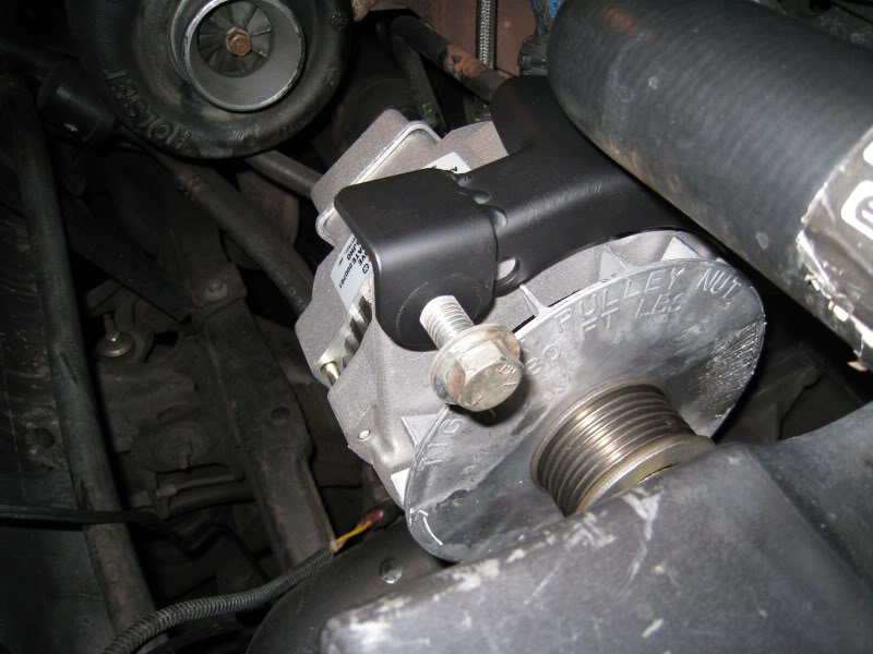
When you are sure everything is straight you can tighten the through bolt and the 1/2�-13 UNC bolt and then you should run up a nut to the backside and snug it up.
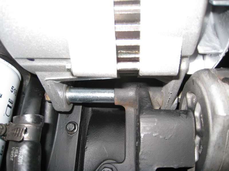
And then go ahead and tighten the 3/8� NF bolt at the bottom of the alternator, as you tighten the bolt it will draw in the movable slug at the rear of the alternator and bring the unit into alignment with the lower bracket.
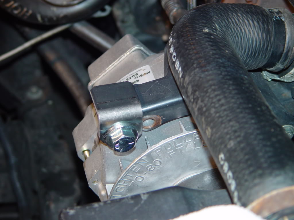
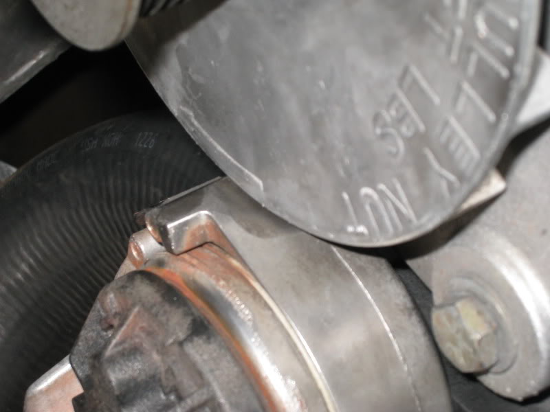
Now the alternator is installed and you need to check for any interference with any of the moving parts. Because I chose to keep the alternator close to the side of the engine the edge of the fan has a bit of interference with the top of the belt tensioner, I found that different brands of tensioner have different characteristics of the housing meaning some will rub and some will not.
My factory tensioner did not rub while the replacement Dayco unit did so to fix the problem I made a mark where the fan would strike the housing and then I removed the tensioner and carefully cut away part of the casting using my 4� angle grinder.
Be careful when you clearance this and only remove enough metal so it will clear.
The casting is thick at this point but still do not cut too deep.
Tip: If you were the kind of person who carries spare parts it would be wise to grind away this spot on your spare so you are not trying to figure out why it is scraping when you replace it on the side of the road and you are grinding away at it with a file.
Alternately you could eliminate this problem by moving the alternator closer into the engine before welding on the tab however doing so will cover the factory hole and render it useless if you wanted to be able to reinstall your Nippondenso alternator.
Now we need to temporarily install the upper alternator bracket into place, install the through bolt and snug it up and then pull the alternator up against the side of the engine.
Then to secure the alternator I installed a metal tab that is 1 �� x 1 �� x 3/16� thick that is drilled to accept the ��-13 UNC bolt.
You can make one by taking a piece of 3/6� flat stock 1 �� wide x 3� long and first drill a 1/2� hole 1/2� from the edge, radius the end with the hole in it and then bend it up at 90* to make the bracket
Note: Please PM me if you have any questions as to where you can obtain this ready-formed bracket.
Then I inserted the ��-13 UNC bolt and washer through the bracket and secured it into the top mount of the alternator.
I then positioned the alternator so the end of the bracket is past the hole for the factory bolt and then after I angled the bracket down flush with the top edge of the top mount I then marked it with a scribe.
I then clamped the bracket with a pair of vice grips and then removed the entire top bracket and the tab then using my wire feed welder I tacked the edge of the tab to the bracket to hold it while I adjusted it.
With the tab tacked I reinstalled the top bracket to the engine and reinstalled the ��-13 UNC bolt and washer to the alternator, with the one side tacked it was easy to move it into position to its final position; after it was where I wanted it I again removed the bracket and finished welding the tab.
The reason that I installed the new mounting tab on the outside of the hole was this way if I ever wanted or needed to reinstall the factory Nippondenso alternator the entire conversion could be reversed and be back to factory within about 10 minuets time.
After I was sure of the fit I removed the bracket and after a quick deburring and washing it down with lacquer thinner I gave it a quick coat of paint and let it dry.
Then I installed it onto the engine.
Before I positioned the bracket onto the top mount I inserted a piece of polyurethane between the side of the alternator case and the side of the bypass hose to protect the hose from rubbing against the side of the rough case then I aligned the bracket and insert the long through bolt.
Do not tighten the bolt at this time.
Now you can lift the bracket and swing the alternator into place and then install the ��-13 UNC bolt and washer
When you are sure everything is straight you can tighten the through bolt and the 1/2�-13 UNC bolt and then you should run up a nut to the backside and snug it up.
And then go ahead and tighten the 3/8� NF bolt at the bottom of the alternator, as you tighten the bolt it will draw in the movable slug at the rear of the alternator and bring the unit into alignment with the lower bracket.
Now the alternator is installed and you need to check for any interference with any of the moving parts. Because I chose to keep the alternator close to the side of the engine the edge of the fan has a bit of interference with the top of the belt tensioner, I found that different brands of tensioner have different characteristics of the housing meaning some will rub and some will not.
My factory tensioner did not rub while the replacement Dayco unit did so to fix the problem I made a mark where the fan would strike the housing and then I removed the tensioner and carefully cut away part of the casting using my 4� angle grinder.
Be careful when you clearance this and only remove enough metal so it will clear.
The casting is thick at this point but still do not cut too deep.
Tip: If you were the kind of person who carries spare parts it would be wise to grind away this spot on your spare so you are not trying to figure out why it is scraping when you replace it on the side of the road and you are grinding away at it with a file.
Alternately you could eliminate this problem by moving the alternator closer into the engine before welding on the tab however doing so will cover the factory hole and render it useless if you wanted to be able to reinstall your Nippondenso alternator.
07-12-2009, 06:53 AM
#4
Administrator
Thread Starter
Part-4
Now that the alternator is mounted to the engine we have to get all of this awesome power to the battery.
So I started by laying out the path of the wire, I am going to use #2 welding cable, would you believe that the factory alternator was trying to push 120-amps through a tiny little #6-gauge wire and you wondered why you couldn�t keep your battery charged.
The #2 welding cable that I will be using has 651 strands of 30-gauge copper and is wrapped in a tough cover that is oil, abrasion and heat resistant.
To terminate the ends of the wire I will be placing copper lugs to the end of the prepared wire strands and then mechanically crimping them using my rotating jaw crimper. This crimper is so powerful that it will physically bond the copper strands to the copper lug as one.
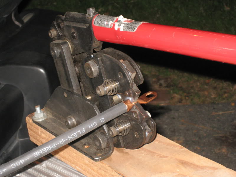
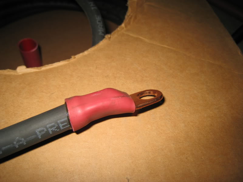
And then to protect and insulate the lug I applied heavy wall adhesive lined shrink tubing and using my heat gun I shrunk it onto the lug for an air and moisture tight seal.
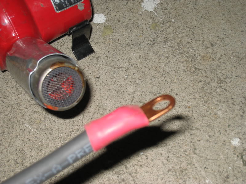
See how the adhesive seals all of the voids for a prefect seal.
After I measured and made my positive charging cable and terminated both of the ends I protected the jacket of the welding cable by slipping it inside of some split loom, I routed the cable from the alternator up onto the top of the engine and I followed the path of the heater coolant lines to the rear of the engine keeping it to the outside so it is not on top of the exhaust manifold.
Someday I am going to fabricate a heat shield to protect my wiring from the heat of the exhaust manifold.
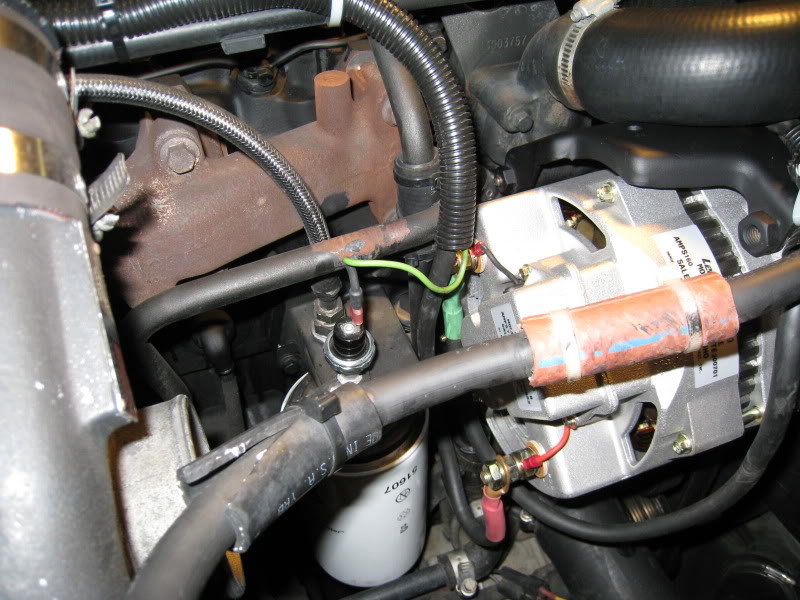
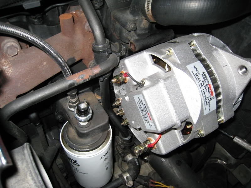
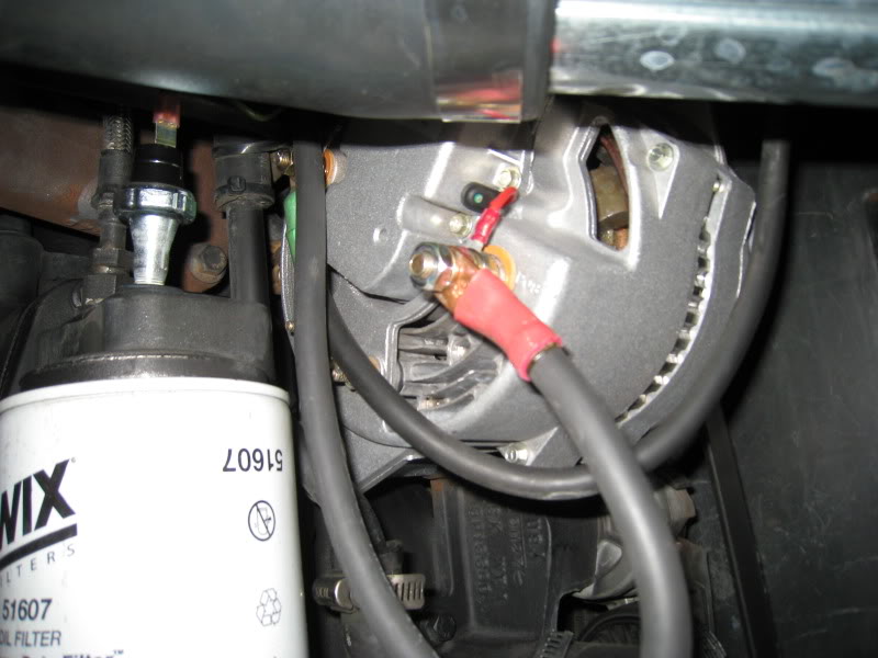
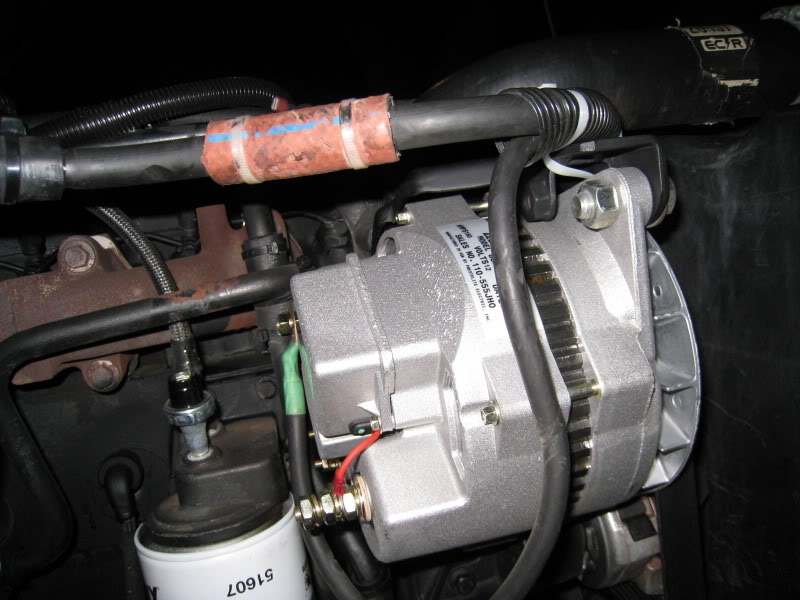
Here you can see how I routed and connected my cables to the rear of the alternator, they were then secured from movement and have enough slack incase I need to make some future modifications.
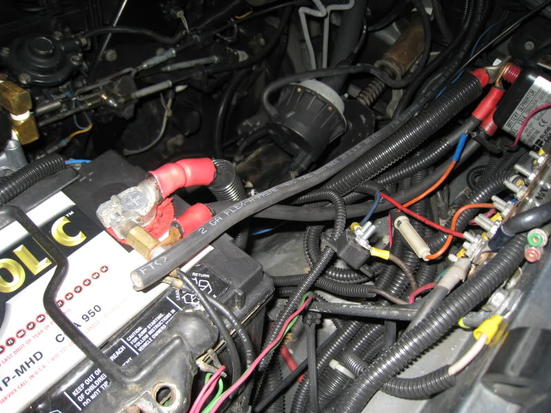
And then from the back of the engine I crossed the back of the firewall over the brake booster and down along the factory harness ending up at the battery.
Next I made a #2 Ground cable with the appropriate color shrink tubing and connected it to the GND terminal on the rear of the alternator.
The opposites end of the ground cable is terminated under a bolt at the front of the engine where my auxiliary battery is also grounded.
The cable that you see just below it is the end to my main battery cable ground and then from the side of the block down by the vacuum pump there is another cable that grounds the engine to the frame.
The piece of red hose is to protect the Ground cable where it passes over the 4� aluminum tubing from the air box to the turbocharger.
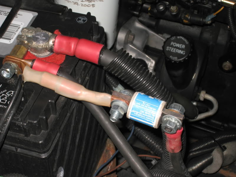
Here you can see how I mounted my 200-amp T-Fuse to the battery by making a short pigtail of welding cable, this is only temporary until I mount the fuse holder somewhere on the fender well or side panel.
This fuse is necessary to protect the alternator and the cable in the event of a catastrophic short circuit, without the fuse and a short circuit were to occur the wire would become white hot before it either melted or the battery exploded sending molten lead and acid everywhere, I have seen this happen.
Now that the alternator is mounted to the engine we have to get all of this awesome power to the battery.
So I started by laying out the path of the wire, I am going to use #2 welding cable, would you believe that the factory alternator was trying to push 120-amps through a tiny little #6-gauge wire and you wondered why you couldn�t keep your battery charged.
The #2 welding cable that I will be using has 651 strands of 30-gauge copper and is wrapped in a tough cover that is oil, abrasion and heat resistant.
To terminate the ends of the wire I will be placing copper lugs to the end of the prepared wire strands and then mechanically crimping them using my rotating jaw crimper. This crimper is so powerful that it will physically bond the copper strands to the copper lug as one.
And then to protect and insulate the lug I applied heavy wall adhesive lined shrink tubing and using my heat gun I shrunk it onto the lug for an air and moisture tight seal.
See how the adhesive seals all of the voids for a prefect seal.
After I measured and made my positive charging cable and terminated both of the ends I protected the jacket of the welding cable by slipping it inside of some split loom, I routed the cable from the alternator up onto the top of the engine and I followed the path of the heater coolant lines to the rear of the engine keeping it to the outside so it is not on top of the exhaust manifold.
Someday I am going to fabricate a heat shield to protect my wiring from the heat of the exhaust manifold.
Here you can see how I routed and connected my cables to the rear of the alternator, they were then secured from movement and have enough slack incase I need to make some future modifications.
And then from the back of the engine I crossed the back of the firewall over the brake booster and down along the factory harness ending up at the battery.
Next I made a #2 Ground cable with the appropriate color shrink tubing and connected it to the GND terminal on the rear of the alternator.
The opposites end of the ground cable is terminated under a bolt at the front of the engine where my auxiliary battery is also grounded.
The cable that you see just below it is the end to my main battery cable ground and then from the side of the block down by the vacuum pump there is another cable that grounds the engine to the frame.
The piece of red hose is to protect the Ground cable where it passes over the 4� aluminum tubing from the air box to the turbocharger.
Here you can see how I mounted my 200-amp T-Fuse to the battery by making a short pigtail of welding cable, this is only temporary until I mount the fuse holder somewhere on the fender well or side panel.
This fuse is necessary to protect the alternator and the cable in the event of a catastrophic short circuit, without the fuse and a short circuit were to occur the wire would become white hot before it either melted or the battery exploded sending molten lead and acid everywhere, I have seen this happen.
07-12-2009, 06:55 AM
#5
Administrator
Thread Starter
Part-5
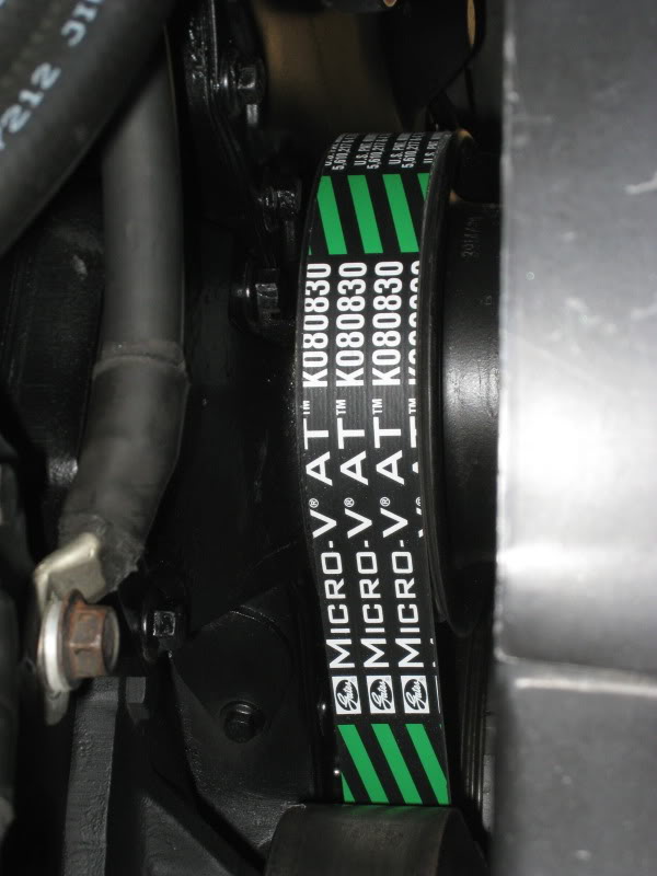
At this time you can install your new serpentine belt you will need to get a longer one to fit the new alternator.
Gates Micro-V AT #K080830 will fit if you are installing this on a NON-intercooled engine with this particular size pulley, this is what works on my truck.
I do not have any information as to the different size belts and their respective part numbers but if after enough members install these alternators using various sized pulleys please post your feedback let me know the diameter of the pulley and the belt size and part number that worked for you so I could create a database or list of belt numbers that would work for the various sized pulleys.
If someone was good in math they could take the size of my belt and figure out the different lengths by the diameter of the different pulleys.
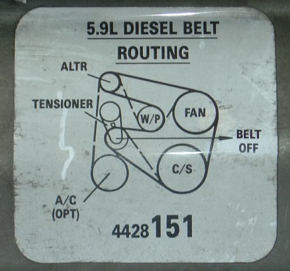
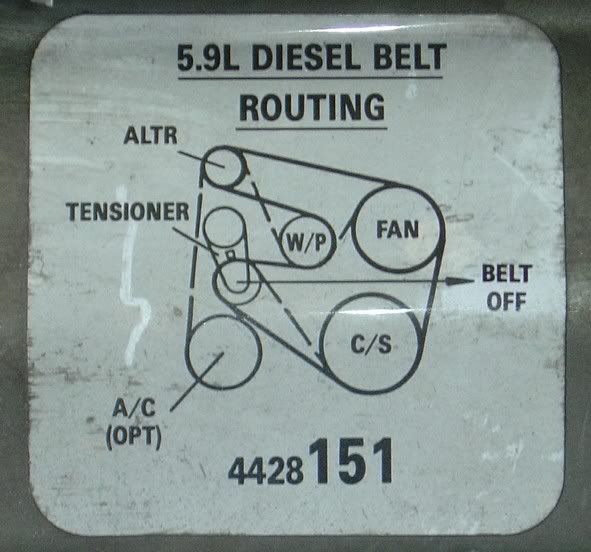
I have included the Belt Routing Diagram incase you need it.
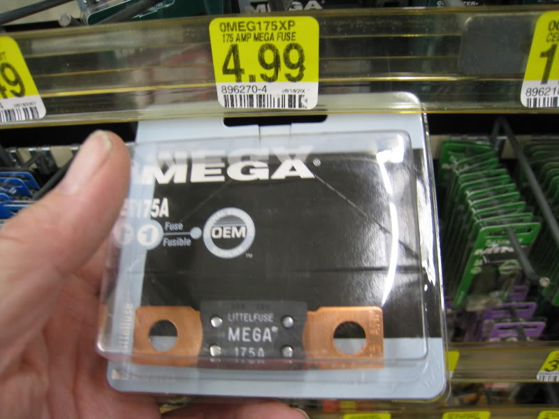
This is an acceptable power fuse that you could use, it is from Pep Boys.
This completes the conversion, all that is needed is for you to go and recheck all of the bolts and make sure there is nothing loose that could get in the way of any moving parts.
It is now time to reconnect your battery and then start your engine.
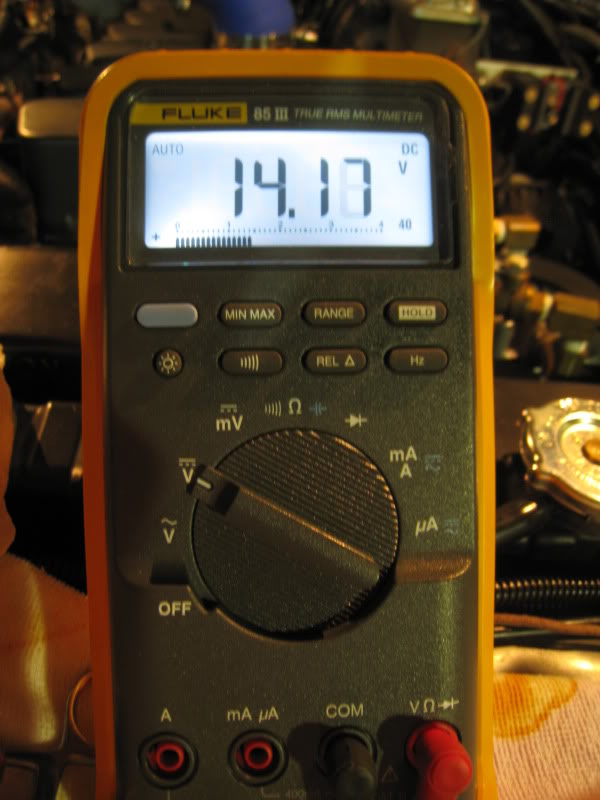
At this time I would recommend with a DMM that you check your battery voltage at the battery with the engine idling it should have somewhere around 13.80 volts.
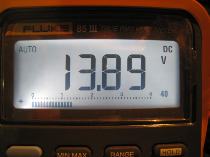
This is taken off the BAT. Terminal of the alternator.
If you have your headlights on relays you will notice they are now much brighter however it would be wise to install a voltage regulator to lower the voltage a bit to the headlamps to prolong their life.
I will show you how to do this in a future post.
Ok the discussion has come up about the proper size pulley to install.
This will give you some basic formulas to calculate your pulley size according to if your engine is Intercooled or NON-Intercooled because of the difference in the size of the crankshaft pulley and also you need to compensate for your transmission type and final gear ratio.
Non-Intercooled
6.50/2.70=2.41:1 x 800RPM=1925.925925 Idle RPM
6.50/2.70=2.41:1 x 3200 RPM=7703.703702 Maximum RPM
Intercooled
8.0/2.70=2.962962962:1 x 800=2370.370369 Idle RPM
8.0/2.70=2.962962962:1 x 3200=9481.481478 Maximum RPM
8.0/3.0=2.666666666:1 x 800=2133.333332 Idle RPM
8.0/3.0=2.666666666:1 x 3200=8533.333331 Maximum RPM
8.0/3.25=2.461538461:1 x 800= 1969.230768 Idle RPM
8.0/3.25=2.461538461:1 x 3200=7876.923075 Maximum RPM
The alternator is rated for 6000-RPM Continuous so depending on if your truck is an Automatic or a Manual and then factoring in your final gear ratio.
I calculated the maximum speed of 3200 RPM assuming you have upgraded the governor spring.
You would have to look at your driving habits and ask if you wind out the engine against the governor between gears.
The top speed of the 110-555JHO alternators should be limited to approximately 5000 to 6000 maximum continuous RPM.
I think I would choose the size to have it close to 2000 RPM�s for a good Idle Speed charge (if you really need this much power at an idle) and to have it somewhere in the middle to upper part of the power band while cruising.
Also remember that I called 800 RPM as a Fast Idle where the actual idle speeds will be somewhat lower reducing the low idle output only by about 20-amps.
I really do not want to make this too complicated, unless you drag race your truck just pick small pulley for a non-intercooled and a larger pulley if it is intercooled and call it good.
Parts List, What you will need:
Leece Neville 110-555JHO 160-amp alternator.
Or
Leece Neville 110-555HD 140-amp alternator.
8-Groove Serpentine Pulley 2.70 nominal diameter but may range up to 3.50� diameter.
Appropriate length serpentine belt.
Bypass Hose Dayco #80400
1- 3/8�x 6� NF Grade-8 bolt.
1- 3/8� NF Grade-8 Nut.
2- 3/8� Machine Washers.
1- 1/2� �13 UNC x 2� Bolt.
1- �� Machine Washer or common Cut Washer.
1- Spacer 4� x 3/8� ID to be cut to 2� long.
1- Spacer 3/8� ID x �� OD about 2� long to be cut �� and 5/8� long.
1 �� x 3� x 3/16� flat stock to make the top mounting tab.
PM me for details on how to secure a ready-made bracket.
Length of #2 welding cable to connect the alternator to the battery and to make ground cable.
4- #2-gauge copper lugs with 3/8� eyelet.
175-amp Fuse
Length of �� split convoluted loom to protect welding cable.
Heavy Wall Adhesive Lined Heat Shrink Tubing. With means to shrink and set adhesive.
Miscellaneous parts you will need:
TyRaps (ZipTie)
Section of 5/8� heater hose to protect the coolant pipe.
Tools you will need to complete this conversion:
Vise
Hacksaw
Files
Set of SAE and Metric Wrenches.
Cable Crimper or other means to install lugs onto the welding cable.
Power Drill and Drill Bits.
Impact Wrench to install pulley nut.
Access to a Lathe to machine the step of from the backside of the pulley.
Silicone to secure the bushings inside of the alternator ears.
Angle Grinder to cut relief in Idler Pulley casting.
Access to a welder.
This conversion if you were to purchase your 110-555JHO alternators new with all of the parts shouldn�t cost you more than $275.00
If you see any errors, things that I might have missed or ways to improve this conversion please let me know.
This conversion is not difficult; it will require basic comprehension and fabrication skills to measure, cut and to follow directions.
If you are not confident in your wiring skills I would suggest you enlist someone who is.
This alternator and the required connections are generating and carrying dangerous amounts of current.
But by simply following my instructions you should not have any problems but if you are not sure of something or have any questions please feel free to ask.
Useful Information from Prestolite/ Leece Neville:
http://www.prestolite.com/pgs_suppor...ct_guide_b.php
http://www.prestolite.com/pgs_support/min_wire_size.php
http://www.prestolite.com/pgs_support/alt_charge.php
http://www.prestolite.com/literature...nual_lores.pdf
http://www.prestolite.com/index-na.php
Again thank you for letting me entertain you with my knowledge.
I may be updating this post from time to time.
Jim
At this time you can install your new serpentine belt you will need to get a longer one to fit the new alternator.
Gates Micro-V AT #K080830 will fit if you are installing this on a NON-intercooled engine with this particular size pulley, this is what works on my truck.
I do not have any information as to the different size belts and their respective part numbers but if after enough members install these alternators using various sized pulleys please post your feedback let me know the diameter of the pulley and the belt size and part number that worked for you so I could create a database or list of belt numbers that would work for the various sized pulleys.
If someone was good in math they could take the size of my belt and figure out the different lengths by the diameter of the different pulleys.
I have included the Belt Routing Diagram incase you need it.
This is an acceptable power fuse that you could use, it is from Pep Boys.
This completes the conversion, all that is needed is for you to go and recheck all of the bolts and make sure there is nothing loose that could get in the way of any moving parts.
It is now time to reconnect your battery and then start your engine.
At this time I would recommend with a DMM that you check your battery voltage at the battery with the engine idling it should have somewhere around 13.80 volts.
This is taken off the BAT. Terminal of the alternator.
If you have your headlights on relays you will notice they are now much brighter however it would be wise to install a voltage regulator to lower the voltage a bit to the headlamps to prolong their life.
I will show you how to do this in a future post.
Ok the discussion has come up about the proper size pulley to install.
This will give you some basic formulas to calculate your pulley size according to if your engine is Intercooled or NON-Intercooled because of the difference in the size of the crankshaft pulley and also you need to compensate for your transmission type and final gear ratio.
Non-Intercooled
6.50/2.70=2.41:1 x 800RPM=1925.925925 Idle RPM
6.50/2.70=2.41:1 x 3200 RPM=7703.703702 Maximum RPM
Intercooled
8.0/2.70=2.962962962:1 x 800=2370.370369 Idle RPM
8.0/2.70=2.962962962:1 x 3200=9481.481478 Maximum RPM
8.0/3.0=2.666666666:1 x 800=2133.333332 Idle RPM
8.0/3.0=2.666666666:1 x 3200=8533.333331 Maximum RPM
8.0/3.25=2.461538461:1 x 800= 1969.230768 Idle RPM
8.0/3.25=2.461538461:1 x 3200=7876.923075 Maximum RPM
The alternator is rated for 6000-RPM Continuous so depending on if your truck is an Automatic or a Manual and then factoring in your final gear ratio.
I calculated the maximum speed of 3200 RPM assuming you have upgraded the governor spring.
You would have to look at your driving habits and ask if you wind out the engine against the governor between gears.
The top speed of the 110-555JHO alternators should be limited to approximately 5000 to 6000 maximum continuous RPM.
I think I would choose the size to have it close to 2000 RPM�s for a good Idle Speed charge (if you really need this much power at an idle) and to have it somewhere in the middle to upper part of the power band while cruising.
Also remember that I called 800 RPM as a Fast Idle where the actual idle speeds will be somewhat lower reducing the low idle output only by about 20-amps.
I really do not want to make this too complicated, unless you drag race your truck just pick small pulley for a non-intercooled and a larger pulley if it is intercooled and call it good.
Parts List, What you will need:
Leece Neville 110-555JHO 160-amp alternator.
Or
Leece Neville 110-555HD 140-amp alternator.
8-Groove Serpentine Pulley 2.70 nominal diameter but may range up to 3.50� diameter.
Appropriate length serpentine belt.
Bypass Hose Dayco #80400
1- 3/8�x 6� NF Grade-8 bolt.
1- 3/8� NF Grade-8 Nut.
2- 3/8� Machine Washers.
1- 1/2� �13 UNC x 2� Bolt.
1- �� Machine Washer or common Cut Washer.
1- Spacer 4� x 3/8� ID to be cut to 2� long.
1- Spacer 3/8� ID x �� OD about 2� long to be cut �� and 5/8� long.
1 �� x 3� x 3/16� flat stock to make the top mounting tab.
PM me for details on how to secure a ready-made bracket.
Length of #2 welding cable to connect the alternator to the battery and to make ground cable.
4- #2-gauge copper lugs with 3/8� eyelet.
175-amp Fuse
Length of �� split convoluted loom to protect welding cable.
Heavy Wall Adhesive Lined Heat Shrink Tubing. With means to shrink and set adhesive.
Miscellaneous parts you will need:
TyRaps (ZipTie)
Section of 5/8� heater hose to protect the coolant pipe.
Tools you will need to complete this conversion:
Vise
Hacksaw
Files
Set of SAE and Metric Wrenches.
Cable Crimper or other means to install lugs onto the welding cable.
Power Drill and Drill Bits.
Impact Wrench to install pulley nut.
Access to a Lathe to machine the step of from the backside of the pulley.
Silicone to secure the bushings inside of the alternator ears.
Angle Grinder to cut relief in Idler Pulley casting.
Access to a welder.
This conversion if you were to purchase your 110-555JHO alternators new with all of the parts shouldn�t cost you more than $275.00
If you see any errors, things that I might have missed or ways to improve this conversion please let me know.
This conversion is not difficult; it will require basic comprehension and fabrication skills to measure, cut and to follow directions.
If you are not confident in your wiring skills I would suggest you enlist someone who is.
This alternator and the required connections are generating and carrying dangerous amounts of current.
But by simply following my instructions you should not have any problems but if you are not sure of something or have any questions please feel free to ask.
Useful Information from Prestolite/ Leece Neville:
http://www.prestolite.com/pgs_suppor...ct_guide_b.php
http://www.prestolite.com/pgs_support/min_wire_size.php
http://www.prestolite.com/pgs_support/alt_charge.php
http://www.prestolite.com/literature...nual_lores.pdf
http://www.prestolite.com/index-na.php
Again thank you for letting me entertain you with my knowledge.
I may be updating this post from time to time.
Jim
07-13-2009, 08:34 PM
#7
Registered User

THANK YOU
JIM LANE
Is it possible to show this "spacer" you speak of ??
On the units I have, the inside surface of the fan has a shoulder---maybe an eighth thick, but no spacer behind the fan that I can see, unless it is something that doesn't slide off easily and I am mistaking it for the bearing.
When I test-fit and temporarily installed a pulley, the fan does not interfere with the case in any way and spins smoothly.
What should this "spacer" look like ??
Does the shoulder on my fan eliminate the need for the spacer ??
Thanks.

Trending Topics
07-13-2009, 08:45 PM
#8
Registered User
Okay, looking at the 90* "ear" that you welded onto the factory upper bracket, is the front surface of the alternator "ear" flush with the forward/outer surface of the factory bracket (it looks so in the pictures) ??
Thanks.
Thanks.
07-14-2009, 01:24 AM
#9
Administrator
Thread Starter
THANK YOU
JIM LANE
Is it possible to show this "spacer" you speak of ??
On the units I have, the inside surface of the fan has a shoulder---maybe an eighth thick, but no spacer behind the fan that I can see, unless it is something that doesn't slide off easily and I am mistaking it for the bearing.
When I test-fit and temporarily installed a pulley, the fan does not interfere with the case in any way and spins smoothly.
What should this "spacer" look like ??
Does the shoulder on my fan eliminate the need for the spacer ??
Thanks.
That is correct one of the earlier units that I had the rear of the fan was flat and there was a spacer between the back of the fan and the bearing, I am sure there has been many variants of this design but all of the later ones that I have seen have a step on the back side of the fan.
So if there is some chance yours has a separate spacer I would just want you to be aware so you don�t install the pulley and damage the fan, housing or possibly the bearing.
Look at page #4 and look at the picture of the fan and then go to page #5 and the picture shows a hub on the backside of the fan.
http://www.prestolite.com/literature...s_list-web.pdf
I had been putting all of this together for the last few months in the middle of all of the other projects that I have been doing, and this took a bit longer to choreograph the 40 some pictures in the proper sequence to make this as painless and bulletproof as possible for you guys.
Some of the questions that you have been asking were added to the storyline and I didn�t want to let on about what was to come.
Jim
07-14-2009, 01:28 AM
#10
Administrator
Thread Starter
07-14-2009, 11:20 PM
#11
Registered User
Length of �� split convoluted loom to protect welding cable.
Silicone to secure the bushings inside of the alternator ears.

I am waiting on pulleys and have yet to buy the cable and order the fuses/holders.
I am hoping that the longer belt that works with my retrofitted Ford alternator will also work with the Leece-Neville; old always prepared me will have several brand-new very expensive Gates to hopefully swap back to the auto-parts if it don't work out.
 07-15-2009, 01:19 AM
#12
Registered User
For those who might not know, most brands of belts will tell you all you need to know right in the part-number.

For instance, the belt in the picture, #080830, is 08 = 8-ribs, 083 = 83-inches long, 0 = the belt is not plus half-an-inch.
If instead the number were 080835, the belt would be 83-1/2" long; belts are available in 1/2" increments.
Another example :
The special longer non-A/C belt that I use on my Ford alternator equipped engine is 080670, meaning an 8-rib belt that is 67-inches long.
For those who are wondering, my A/C and trailer-vacuum are driven by a seperate V-belt, thus the much shorter serpentine non-A/C belt.
I find it interesting that JIMs non-I/C Leece-Neville belt just happens to be standard issue for an I/C truck with A/C = 080830, so he should be able to get around the much more expensive special order belts that some of us are going to require.
The standard issue belt for a non-I/C truck with A/C is 080820, only one-inch shorter than the 080830.
Here is the list of standard issue belts :
Non-I/C with A/C = 080820
Non-I/C no A/C = 080650
I/C with A/C = 080830
I/C no A/C = 080640
I also find it puzzling that, although the I/C-A/C belt is an inch longer than the non-I/C-A/C belt, the I/C-NO-A/C belt is an inch shorter than the non-I/C-NO-A/C belt; this confuses me.
Another interesting scenario is that, when the wife's old A/C compressor locked up, although her truck calls for non-A/C belt number 080640, a 64-inch belt, she ran around for weeks with one of my spare 080670 67-inch belts, three-inches longer, with no obvious issues with belt slippage.
This leads me to believe that we have quite a bit of lee-way in belt length and that a couple inches, one way or another, has little negative effect.
One other point :
If some math genius decides to calculate pulley diameters, center-to-centers, and belt-routing, and thus mathematically determine an appropriate belt length, one must keep in mind that only a portion of the circumference of each pulley actually has belt riding on it, and one would need to know for just how much of that circumference the belt is actually on each pulley; not so easy now, is it.
A better plan is to ascertain all pulley diameters and all center-to-center measurements, angles of relation, etc., along with belt-routing.
Then, with compass, protractor, rule, and straight-edge, draw a full-scale drawing of the belt-routing on a big piece of poster-board, taking into consideration exactly where the tensioner pulley will be when a belt is present.
A trick I have often used is to take the strap from one of those inch-wide ratchet-straps and, while someone holds the tensioner where it should be, rout the strap around the belt's path, pulling the strap snug by hand (no ratchet), and marking the point where the two strap-ends overlap; mark BOTH ends of the strap and measure the distance between the marks; that measurement will be your needed belt length.
07-15-2009, 05:56 AM
#13
Administrator
Thread Starter
The two studs on the back of the alternator are 5/16 and 1/4; is there a reason for using 3/8-eyelet lugs at those two points ??
There is no reason.
I bought an assortment of Copper Lugs at my local Welding Supply and there was not a very large assortment of sizes. I bought some with both 5/16" and 3/8" eyelets, and I actually did use 5/16� on the alternator side.
Correction:
2- #2-Gauge copper lugs with 3/8� eyelet.
2- #2-Gauge copper lug with 5/16� eyelet.
As soon as I can figure out how to edit my original post I will make the corrections.
1/2" inside diameter, right ??
Yes, correct nothing critical you just want to help protect the jacket of the cable.
If I ever get finished making all of my changes I am going to cover all of the welding cables under my hood using some BRAIDED NYLON SLEEVING
I think it looks a lot nicer and the sleeving will conform to the size of the cable.
It is just a bit more difficult to use on a run with any branch circuits where I will continue to use the split loom.
��
http://cgi.ebay.com/1-2-BRAIDED-NYLO...3A1%7C294%3A50
7/8�
http://cgi.ebay.com/7-8-BRAIDED-NYLO...3A1%7C294%3A50
I have used Braided Kevlar Sleeving on a couple of applications where it had to be flame retardant.
http://www.cabletiesandmore.com/BraidedSleeving.php
My plan is to use the hot-melt glue gun for this step; of course, sometimes my plans back-fire.
That should work just fine you could even use some Nail Polish to secure the bushing as long as you ask your wife first.
I am waiting on pulleys and have yet to buy the cable and order the fuses/holders.
So what size pulleys have you acquired so far? I am curious as to how you are determining the ratio you are trying for?
I am hoping that the longer belt that works with my retrofitted Ford alternator will also work with the Leece-Neville; old always prepared me will have several brand-new very expensive Gates to hopefully swap back to the auto-parts if it don't work out.
Are you going to buy your welding cable locally?
Jim
07-15-2009, 07:18 AM
#14
Administrator
Thread Starter
For those who might not know, most brands of belts will tell you all you need to know right in the part-number.

For instance, the belt in the picture, #080830, is 08 = 8-ribs, 083 = 83-inches long, 0 = the belt is not plus half-an-inch.
If instead the number were 080835, the belt would be 83-1/2" long; belts are available in 1/2" increments.
Another example :
The special longer non-A/C belt that I use on my Ford alternator equipped engine is 080670, meaning an 8-rib belt that is 67-inches long.
For those who are wondering, my A/C and trailer-vacuum are driven by a seperate V-belt, thus the much shorter serpentine non-A/C belt.
I find it interesting that JIMs non-I/C Leece-Neville belt just happens to be standard issue for an I/C truck with A/C = 080830, so he should be able to get around the much more expensive special order belts that some of us are going to require.
The standard issue belt for a non-I/C truck with A/C is 080820, only one-inch shorter than the 080830.
Here is the list of standard issue belts :
Non-I/C with A/C = 080820
Non-I/C no A/C = 080650
I/C with A/C = 080830
I/C no A/C = 080640
I also find it puzzling that, although the I/C-A/C belt is an inch longer than the non-I/C-A/C belt, the I/C-NO-A/C belt is an inch shorter than the non-I/C-NO-A/C belt; this confuses me.
Another interesting scenario is that, when the wife's old A/C compressor locked up, although her truck calls for non-A/C belt number 080640, a 64-inch belt, she ran around for weeks with one of my spare 080670 67-inch belts, three-inches longer, with no obvious issues with belt slippage.
This leads me to believe that we have quite a bit of lee-way in belt length and that a couple inches, one way or another, has little negative effect.
Thanks for posting this information.
I have been trying to calculate the belt that I would need so I can still carry an emergency Non-AC belt, so since I now have a:
Non-IC W/AC & Leece Neville
080830= 83"
Non-IC WO/AC & Leece Neville Emergency
080660= 66"
Non-IC W/AC "Stock Application"
080820= 82"
Non-IC WO/AC "Stock Application"
080650= 65"
Does this look correct?
One other point :
If some math genious decides to calculate pulley diameters, center-to-centers, and belt-routing, and thus mathmatically determine an appropriate belt length, one must keep in mind that only a portion of the circumference of each pulley actually has belt riding on it, and one would need to know for just how much of that circumference the belt is actually on each pulley; not so easy now, is it.
If you have a look at the Belt Routing Diagram you can see that with each belt the actual path around each pulley will change not only the angle of attack but also the direction of the rotation around the idler.
With the:
Non-AC belt the Idler turns Clockwise
AC belt the Idler turns Counterclockwise
It also changes the attack angle to the Idler in relation to the pivot so I am wondering if the actual tension loaded on the belt is different.
So can you see how a belt that is only 1 inch longer by taking a different path can cover the distance of another accessory?
Use your cursor on the diagram above the trace the path of the belt around the pulleys for each option ad you travel around the idler you can see how it changed directions. That is genius
A better plan is to ascertain all pulley diameters and all center-to-center measurements, angles of relation, etc., along with belt-routing.
Then, with compass, protractor, rule, and straight-edge, draw a full-scale drawing of the belt-routing on a big piece of poster-board, taking into consideration exactly where the tensioner pulley will be when a belt is present.
A trick I have often used is to take the strap from one of those inch-wide ratchet-straps and, while someone holds the tensioner where it should be, rout the strap around the belt's path, pulling the strap snug by hand (no ratchet), and marking the point where the two strap-ends overlap; mark BOTH ends of the strap and measure the distance between the marks; that measurement will be your needed belt length.
After enough people do this conversion I hope they will report back and post the Belt number they used with the diameter of the pulley so we can have a list with all of this information.
Hey BK thanks for taking the time to critique all that I write.
Jim
07-15-2009, 07:39 AM
#15
A better plan is to ascertain all pulley diameters and all center-to-center measurements, angles of relation, etc., along with belt-routing.
Then, with compass, protractor, rule, and straight-edge, draw a full-scale drawing of the belt-routing on a big piece of poster-board, taking into consideration exactly where the tensioner pulley will be when a belt is present.
Then, with compass, protractor, rule, and straight-edge, draw a full-scale drawing of the belt-routing on a big piece of poster-board, taking into consideration exactly where the tensioner pulley will be when a belt is present.
