Blower motor


 07-12-2007, 07:27 PM
#47
Administrator
Thread Starter

Exactly, I designed this circuit to only operate in the Hi position since that is where all of the current will be drawn through the wiring and switch contacts.
When it is on the Hi position there is still power in the resistor block but there would be anyways, remember where I said to insulate the terminal that was removed from the blower switch.
BTW. I did this to my truck & went from 10.00 v to 14.00 v with the engine running . . . . .but mine had bad splices from last time motor was replaced.
Did the speed of your blower increase significantly? Mine did by almost double.
I just realized today while driving around town that I was actually driving with the blower down one notch because it was blowing too hard.
It's terrible when it works too well.
Good point. don't I feel dumb now
You should never feel dumb, you just know a little more than you did before you asked.
Jim
07-24-2007, 10:47 PM
#48
Registered User
Join Date: Jun 2007
Location: Dallas Baby!!!!
Posts: 428
Likes: 0
Received 0 Likes
on
0 Posts
The vacuum supply line that goes into the interior, runs right beside the factory vacuum switch for the heater. I cut the supply line right next to the switch and put in a "T" . I attached the 3rd leg of the "T" to the vac port on the heater valve and plugged the original line with a screw. Now, there will never be hot coolant running through the core(I use fresh air mostly)
Should there be another 3 day winter in Texas, I will hook the original line back to the vac switch and use the screw to plug the 3rd leg of the "T".
I think I paid .79 for the rubber T a while back, and the screw, I had.
07-25-2007, 09:30 AM
#50
Registered User
Join Date: Jun 2007
Location: Dallas Baby!!!!
Posts: 428
Likes: 0
Received 0 Likes
on
0 Posts
I did the under hood part last night. I didn't have time to take the dash apart and do the inside part.
A couple of observations.
1. Adding the aux ground to the blower motor, even without getting the relay for the power side installed, makes the blower run stronger. The added strain on the ignition switch is unknown at this time.
2. By putting the T in the source vac line to the heater valve, it dropped the A/C temp by what felt like 20+ degrees. I was frosting up the windows on the way to work, using fresh air. When I went to max, I had to turn it off.
I am going to be so happy when I finish the job on the AC. I have a few more tricks I am going to do to make the compressor cycle, like most cars.
My son once told me that I have a relay fetish. When he got home from work last night he said "What is it with you and putting relays in Mopar vehicles" First the Duster, now this. He was looking at my prototype relay panel that will be putting a relay on every circuit in the fuse panel, virtually elininating all draw across the ignition switch.
I love this site!!!!!!!!!!
07-31-2007, 12:25 PM
#51
Registered User
Join Date: Jun 2003
Location: Northern KS
Posts: 818
Likes: 0
Received 0 Likes
on
0 Posts
There have been some mention of adding an aux fan to the condenser.
I was looking around last night and found a new 10" electric fan I bought for a project years ago. Looks like 10" is about the right height to fit the condenser, you will need two of them to cover it from side to side. I am going to try the one I have soon and see how it works. The depth might be a problem as the grille is pretty close.
http://store.summitracing.com/partde...5&autoview=sku
Andy
08-08-2007, 10:58 PM
#52
Registered User

Join Date: Nov 2004
Location: lorena TX
Posts: 171
Likes: 0
Received 0 Likes
on
0 Posts
Does this sound like I need a new switch? The med 2 already blows harder with the new ground, but there is no difference when switched to high. Now if I run a jumper to the new high speed wire it will blow really hard. I think my switch isn't triggering high speed.
thanks,
Jeremy
thanks,
Jeremy
10-15-2007, 12:19 PM
#53
DTR's "Cooler than ice cubes 14 miles North of North Pole" member
Join Date: Oct 2006
Location: 14mi North of North Pole
Posts: 1,797
Likes: 0
Received 9 Likes
on
8 Posts
I got it done this last week end. Great mod Jim! The motor blows so hard now it's almost like riding my Bike. 
11-06-2007, 02:19 PM
#54
Registered User
Well cold wheather is setting in so I figured I would give this a try. All I can say is wow the fan is almost too loud now. Should have seen the dust fly. Thanks for the info Jim.
the fan is almost too loud now. Should have seen the dust fly. Thanks for the info Jim.
11-06-2007, 11:52 PM
#55
Registered User

Join Date: Oct 2006
Location: Indianapolis, Indianna
Posts: 701
Likes: 0
Received 0 Likes
on
0 Posts
One of these days i'm gonna wire mine to run relays for all speeds & a single 10 gauge power & ground setup . . .That will take load off factory dash wiring completely.
11-07-2007, 12:14 AM
#56
DTR's "Cooler than ice cubes 14 miles North of North Pole" member
Join Date: Oct 2006
Location: 14mi North of North Pole
Posts: 1,797
Likes: 0
Received 9 Likes
on
8 Posts
If you do that you will only have 1 speed (Turbo) cause you will be bypassing the blower resistor. The resistor controls the fan speed by inducing a resistance into the circut on purpose.
11-07-2007, 01:18 AM
#57
Administrator
Thread Starter
The best way to control the blower motor would be to control it directly through a PWM Pulse Width Modulation Controller, it would be infinitely variable and the control inside would consist of a small 5,000 ohm linear taper potentiometer.
PWM works by supplying the motor with full 12 volts only it is being switched on and off from zero to 1,000's of times per second hence the Pulse Width the advantage of this is the motor has full torque from a crawl to full speed and anywhere in between. I use these on some robotic designs I have and on traction motors.
They are not overly complicated to build, integrated circuits for timing the pulse and transistors and MOSFETS or HEXFETS to control the motor.
You could use the same circuit to dim your headlights from off to full on.
Hope I did not loose too many of you.
Jim
11-15-2007, 05:59 AM
#58
Administrator
Thread Starter
Design upgrade.
Optional Heavy Duty 75-amp Bosch Power Relay.
During some routine maintenance under the hood while I was dusting and checking all of the connections I discovered the Blower Relay was running hot during a full load test.
So I got out my Fluke DMM and went in to investigate. I broke the load circuit and found that although the blower was running at 18.0 amperes up from the 16.0 amperes I originally got during the test and installation the relay itself was running quite hot.
A voltage drop across the contact showed there was no resistance from burned contact so I can only assume the relay running at 2/3 load continuously is causing it to run hot, being in a high ambient temperature in close proximity to the turbo does not help.
I will have to check the specifications for the relay to see if there is a temperature rise under full load.
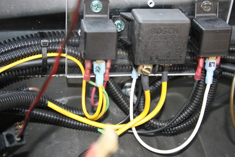
So to upgrade my upgrade and to eliminate the problem I will replace the relay with�
A heavier relay.
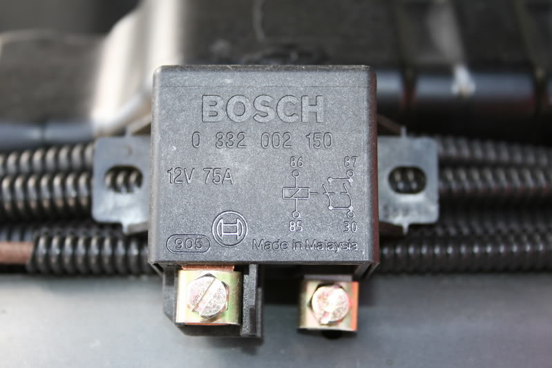
What you are looking at is a Bosch Power Relay rated at 75 amps.
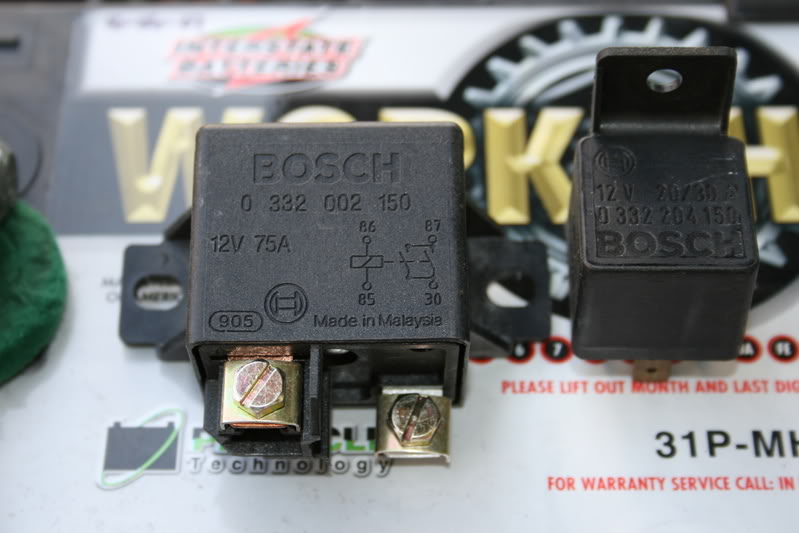
Here is a comparison between the 0-332-002-150 75-amp Power Relay and a standard 0-332-209-150 30-amp relay.
Although the relay is a lot heavier I chose this relay for another reason, inside this relay there are actually 2 sets of contacts, there is a Leading and a Main contact. Instead of trying to explain how it works you can download the Catalog in PDF.
Read the description on page 15.
I have also found a lot of good information in this book to design circuits around.
I already have some applications for the Heavy Duty Power Relays.
http://www.boschmotorsandcontrols.co...ais/relais.pdf
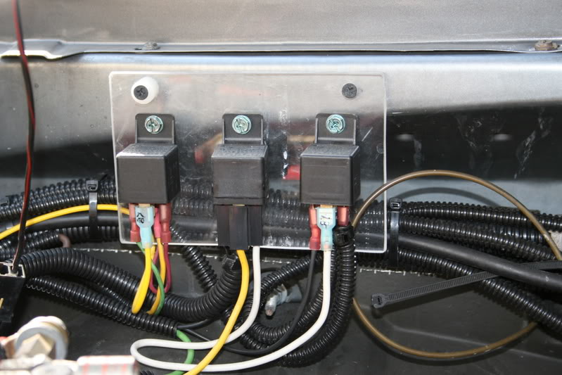
After the relay was mounted I replaced the 12-gauge wiring from the previous relay with even heavier 10-gauge wire for increased current capacity.
All of the terminal designations are the same so you can use the original schematic.
 .
.
This includes increasing the size of the wire to the blower motor for both the Positive (+) and for the Negative (-).
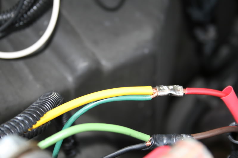
After all of the connections were secured and checked they were sealed using heat shrink tubing.
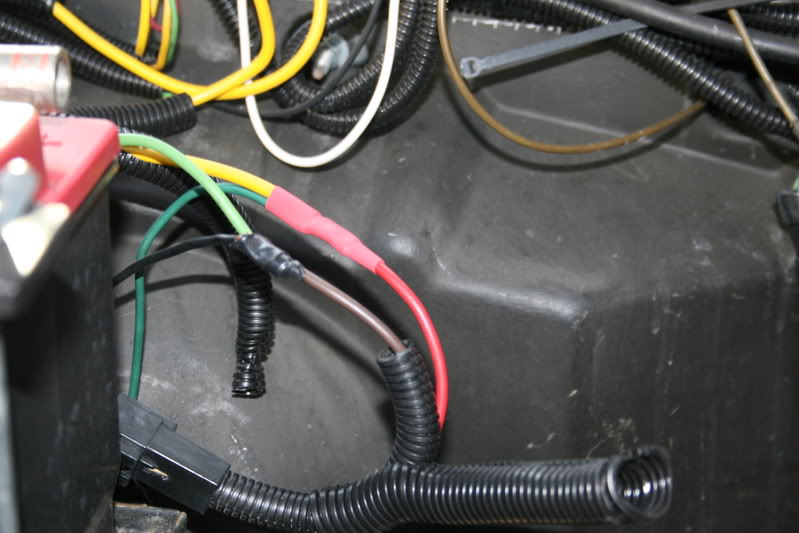
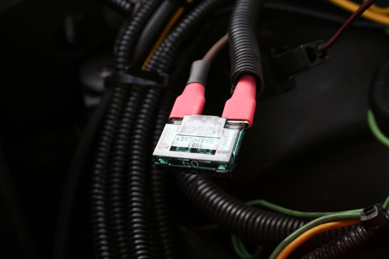
To be able to supply more current to the motor I also increased the size of the fuse for the relay.
(The fuse is a 50 amp in the working circuit.)
After everything was tested it was covered with split loom and secured back into place.
This is not an upgrade that you need to do if you are installing relays for your blower motor for it to work.
I did this because I saw something that might be a problem although the system as I designed it was working fine.
Most people probably do not go around checking the temperature of their wires and relays after they are installed.
In theory the 30 amp relay should be able to control the 18 amp blower motor with no problem but I always like to design a control circuit with at least 2 to 3 times the capacity of the circuit I will be controlling.
As I said before this upgrade is optional.
If you have any questions about anything feel free to ask.
Thanks
Jim
Optional Heavy Duty 75-amp Bosch Power Relay.
During some routine maintenance under the hood while I was dusting and checking all of the connections I discovered the Blower Relay was running hot during a full load test.
So I got out my Fluke DMM and went in to investigate. I broke the load circuit and found that although the blower was running at 18.0 amperes up from the 16.0 amperes I originally got during the test and installation the relay itself was running quite hot.
A voltage drop across the contact showed there was no resistance from burned contact so I can only assume the relay running at 2/3 load continuously is causing it to run hot, being in a high ambient temperature in close proximity to the turbo does not help.
I will have to check the specifications for the relay to see if there is a temperature rise under full load.
So to upgrade my upgrade and to eliminate the problem I will replace the relay with�
A heavier relay.
What you are looking at is a Bosch Power Relay rated at 75 amps.
Here is a comparison between the 0-332-002-150 75-amp Power Relay and a standard 0-332-209-150 30-amp relay.
Although the relay is a lot heavier I chose this relay for another reason, inside this relay there are actually 2 sets of contacts, there is a Leading and a Main contact. Instead of trying to explain how it works you can download the Catalog in PDF.
Read the description on page 15.
I have also found a lot of good information in this book to design circuits around.
I already have some applications for the Heavy Duty Power Relays.
http://www.boschmotorsandcontrols.co...ais/relais.pdf
After the relay was mounted I replaced the 12-gauge wiring from the previous relay with even heavier 10-gauge wire for increased current capacity.
All of the terminal designations are the same so you can use the original schematic.
.This includes increasing the size of the wire to the blower motor for both the Positive (+) and for the Negative (-).
After all of the connections were secured and checked they were sealed using heat shrink tubing.
To be able to supply more current to the motor I also increased the size of the fuse for the relay.
(The fuse is a 50 amp in the working circuit.)
After everything was tested it was covered with split loom and secured back into place.
This is not an upgrade that you need to do if you are installing relays for your blower motor for it to work.
I did this because I saw something that might be a problem although the system as I designed it was working fine.
Most people probably do not go around checking the temperature of their wires and relays after they are installed.
In theory the 30 amp relay should be able to control the 18 amp blower motor with no problem but I always like to design a control circuit with at least 2 to 3 times the capacity of the circuit I will be controlling.
As I said before this upgrade is optional.
If you have any questions about anything feel free to ask.
Thanks
Jim

 11-15-2007, 09:46 PM
#60
Administrator
Thread Starter
You should be able to get these at any well-stocked Truck Parts.
I think I have also seen these on ABS pump motors.
Because of the way the contacts are set up they are good for inductive loads where anything would create an arc when you make or break the connection.
This would be perfect to control your Water-Meth pump if you were having issues with burnt or sticking contacts.
There is also a Power Relay that I use that is the size of a Mini-Relay except that it is a 70-amp instead of the usual 30-amp.
It looks the same except for the Term. #30 & #87 are 1.2mm or 3/8�.
I do not have the Bosch number but the Tyco equivalent is Tyco #VF7-11F11-SO1
I also got this at the same Truck Parts.
But only the big relay has the 2 sets of contacts.
You can see this on page 15 of the Bosch Catalog.
http://www.boschmotorsandcontrols.co...ais/relais.pdf
Jim