
Replace Your Camshaft, Lifters 'n Stuff . . . .

Thread Starter
1st Generation Admin
Joined: Jan 2005
Posts: 4,601
Likes: 118
From: Buies Creek, NC
Folks, this is another attempt to repay the vast knowledge afforded me, by the good people who make these forums what they are today.
This time around, I'm installing an after-market camshaft along with upgraded (for this engine) valve lifters. The work is being done to the typical 1993 Dodge W250 sporting the mighty Cummins (12 valve w/Automatic Trans). NOTE: This should be applicable to ALL 12v 5.9BT CTDs (with or without Inter-cooled and ought to cover the 4BT I think).
You may be looking to simply replace a cam that's got a worn lift-pump lobe or worse, the KDP got the cam gear. This article should be seen as a general over-view of the work involved with removing/replacing the engine's camshaft and lifters with the engine in the truck.
If you're not sure of a step or procedure regarding YOUR truck, start a thread and ask away. That's why we're here . . .. right?
As always ~ SAFETY FIRST!!
- Disconnect the Negative cable of your battery system.
- Chock the wheels and set the parking brake.
- Have a known good fire extinguisher close by.
- Have good lighting.
- Have a clean and orderly work area.
- Always exercise good working practice with your tools.
- Use safety goggles, gloves, masks, etc where appropriate.
- RTFM!
- I always clean the area I plan on working in the night before. Use the engine cleaner of your choice (follow the directions) and forcefully flush everything with a strong garden hose.
Finally know that I'm using the Chrysler Corporation 1993 Service Manual for the D&W 150-350 Ramcharger RWD truck and the Cummins Shop Manual for the B Series engine as my guide in insuring I hit all the bases. This thread is not to be considered "The Authoritive How-To" regarding working on your mess.
Okay?
First, we're gonna have to make some tools. I didn't want to invest in a bunch that I'm only gonna use once (I think).
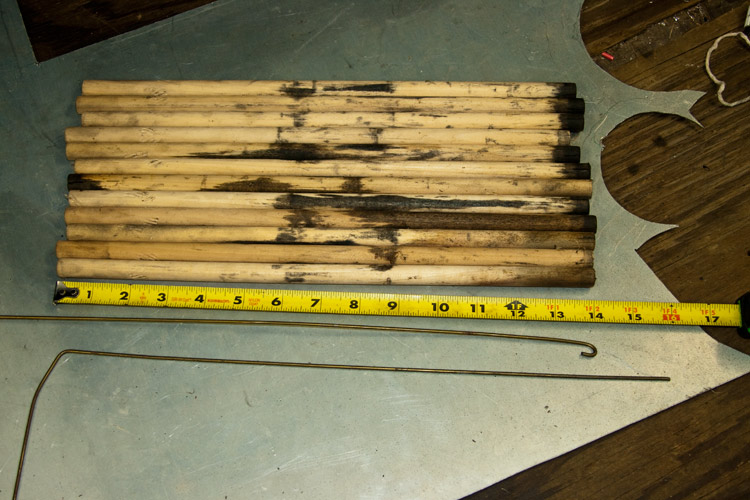
- We need twelve (12) 1/2" OD wooden dowels (Wooden Posts). I got four (4) from Lowes that were 4' long. Cut them so they are at least 14" long.
- Get a coat-hanger and cut a piece about 20" long. Bend it into an "L" shape with the leg about 4" long (L-Tool).
- Get a another coat-hanger and cut a piece about 30" long. Bend a small hook in one end with about a 3/16"" opening (Hook-Tool). It's not critical.
>Pardon the oil stains<
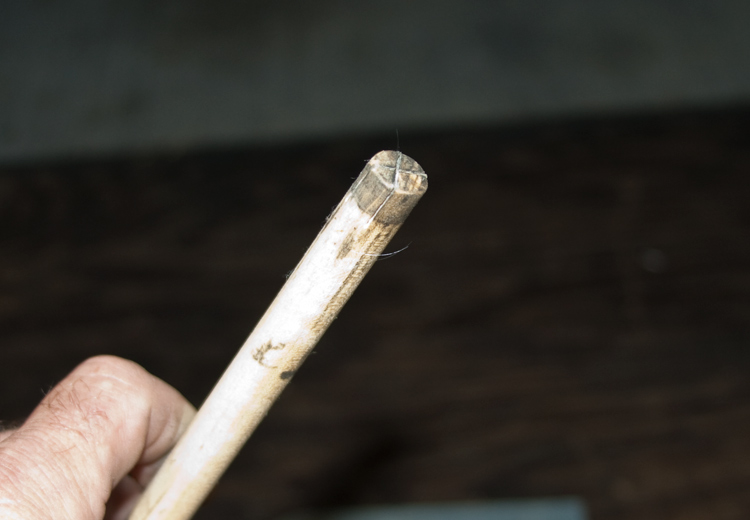
- I used a regular hand-held hack-saw to cut a cross in one end of each post. It's hard to see with the oil but I cut the slots as deep as the hack-saw blade is tall (about 1/2").
- I then slightly beveled the end so as to help it slip into the lifter.
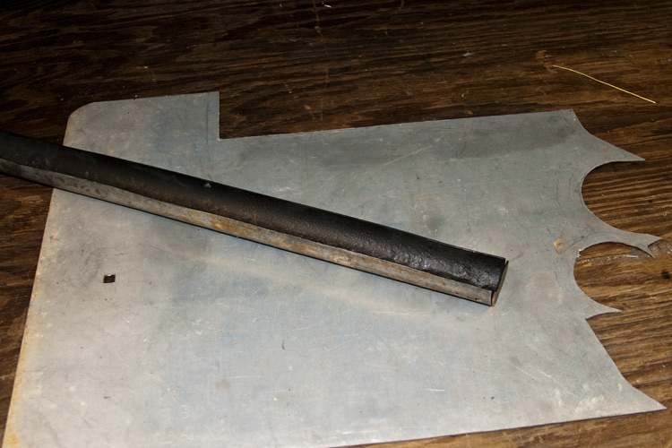
Now we need to make the Trough that will be used to catch/hold the lifters as we work with them.
Some have suggested using a piece of 2" PVC pipe for this. The cam journal is a shade under 2 1/8" in diameter. I don't have any 2" PVC.
Rooting around under the barn I found a piece of 2" EMT electrical conduit.
- I cut a piece about 36" long and cut it in halve lengthwise.
- I then laid one piece on its side and using a hammer, narrowed the trough such that it was right at 2" wide.
- At one end of the Trough, I then made two cuts about an inch from the end. Starting at each side, I cut into the Trough till I had about 3/4" to 1/2" left in the middle. I flattened that small strip of metal and cut it round shaped like this . . . .
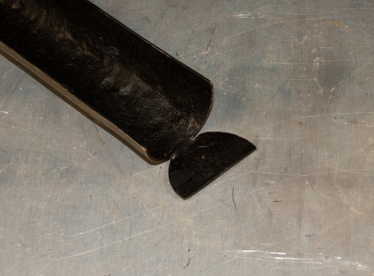
- I then folded that piece up to meet the sides of the Trough thus making an end wall so to speak. From there, I smoothed everything VERY well so as not to scratch the cam bearings. VERY smooth folks.
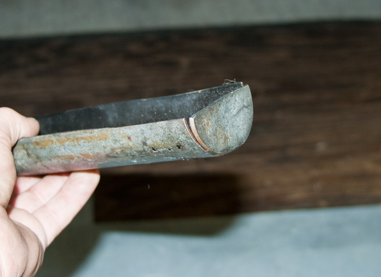
- With that, I painted the interior of the Trough so that the lifters wouldn't pick up any debris while sliding through the trough.
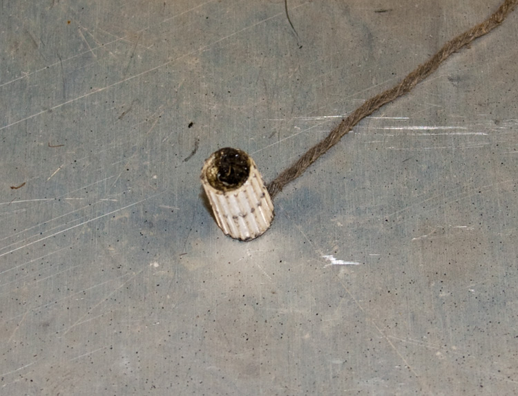
Finally, we need to make the tool that is used to pull the lifters back into their bores of the block. The FSM shows an image of what looks like a small hardwood dowel perhaps 1/2" to 3/4" long with a small Eye-Bolt in one end. Unfortunately, I had soft wood used for the lifter dowels and I figured that wouldn't work. That and I didn't have a small Eye-Bolt.
Here's what I did . . . .
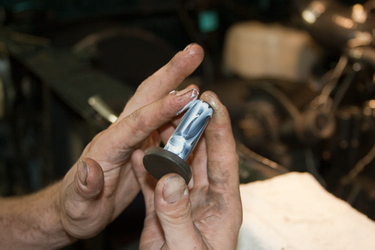
Come to find out that a lid from a common high-lite marker fits perfectly into the push-rod end of the lifters. Huh.
- I shortened the lid so it was now about 3/4" long.
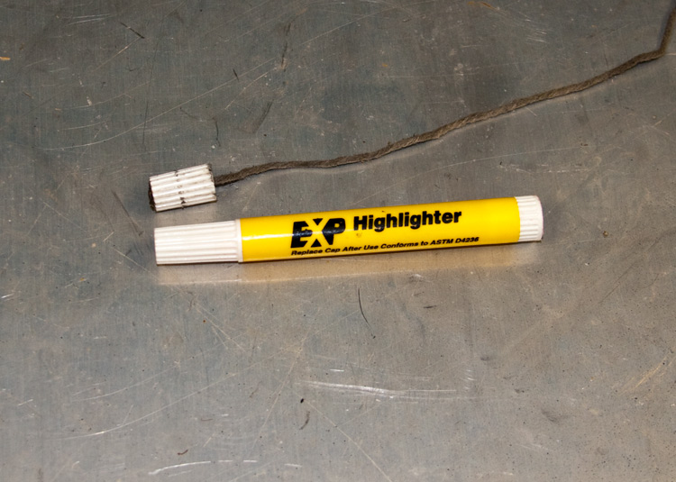
- I then drilled a tiny hole in the closed end just big enough to poke a heavy string through it. Be sure to use string that can repeatedly withstand 10 ~ 15 pounds pull. I made the knot double in size and for good sport, put a booger of contact cement over it all so as to lock it in place. It's as pretty as a rock but it works.
- Now sneak into the woman's hair stuff and get 12 of the simple hair rubber-band thingys. The ones that look like cord but stretch. We'll need them to hold the lifter posts in place when we lift the lifters. Large rubber bands should work just fine but I was concerned the engine oil might mess up the rubber and have the bands fail at the worst time. You'll see.
This time around, I'm installing an after-market camshaft along with upgraded (for this engine) valve lifters. The work is being done to the typical 1993 Dodge W250 sporting the mighty Cummins (12 valve w/Automatic Trans). NOTE: This should be applicable to ALL 12v 5.9BT CTDs (with or without Inter-cooled and ought to cover the 4BT I think).
You may be looking to simply replace a cam that's got a worn lift-pump lobe or worse, the KDP got the cam gear. This article should be seen as a general over-view of the work involved with removing/replacing the engine's camshaft and lifters with the engine in the truck.
If you're not sure of a step or procedure regarding YOUR truck, start a thread and ask away. That's why we're here . . .. right?
As always ~ SAFETY FIRST!!
- Disconnect the Negative cable of your battery system.
- Chock the wheels and set the parking brake.
- Have a known good fire extinguisher close by.
- Have good lighting.
- Have a clean and orderly work area.
- Always exercise good working practice with your tools.
- Use safety goggles, gloves, masks, etc where appropriate.
- RTFM!
- I always clean the area I plan on working in the night before. Use the engine cleaner of your choice (follow the directions) and forcefully flush everything with a strong garden hose.
Finally know that I'm using the Chrysler Corporation 1993 Service Manual for the D&W 150-350 Ramcharger RWD truck and the Cummins Shop Manual for the B Series engine as my guide in insuring I hit all the bases. This thread is not to be considered "The Authoritive How-To" regarding working on your mess.
Okay?
First, we're gonna have to make some tools. I didn't want to invest in a bunch that I'm only gonna use once (I think).
- We need twelve (12) 1/2" OD wooden dowels (Wooden Posts). I got four (4) from Lowes that were 4' long. Cut them so they are at least 14" long.
- Get a coat-hanger and cut a piece about 20" long. Bend it into an "L" shape with the leg about 4" long (L-Tool).
- Get a another coat-hanger and cut a piece about 30" long. Bend a small hook in one end with about a 3/16"" opening (Hook-Tool). It's not critical.
>Pardon the oil stains<
- I used a regular hand-held hack-saw to cut a cross in one end of each post. It's hard to see with the oil but I cut the slots as deep as the hack-saw blade is tall (about 1/2").
- I then slightly beveled the end so as to help it slip into the lifter.
Now we need to make the Trough that will be used to catch/hold the lifters as we work with them.
Some have suggested using a piece of 2" PVC pipe for this. The cam journal is a shade under 2 1/8" in diameter. I don't have any 2" PVC.
Rooting around under the barn I found a piece of 2" EMT electrical conduit.
- I cut a piece about 36" long and cut it in halve lengthwise.
- I then laid one piece on its side and using a hammer, narrowed the trough such that it was right at 2" wide.
- At one end of the Trough, I then made two cuts about an inch from the end. Starting at each side, I cut into the Trough till I had about 3/4" to 1/2" left in the middle. I flattened that small strip of metal and cut it round shaped like this . . . .
- I then folded that piece up to meet the sides of the Trough thus making an end wall so to speak. From there, I smoothed everything VERY well so as not to scratch the cam bearings. VERY smooth folks.
- With that, I painted the interior of the Trough so that the lifters wouldn't pick up any debris while sliding through the trough.
Finally, we need to make the tool that is used to pull the lifters back into their bores of the block. The FSM shows an image of what looks like a small hardwood dowel perhaps 1/2" to 3/4" long with a small Eye-Bolt in one end. Unfortunately, I had soft wood used for the lifter dowels and I figured that wouldn't work. That and I didn't have a small Eye-Bolt.
Here's what I did . . . .
Come to find out that a lid from a common high-lite marker fits perfectly into the push-rod end of the lifters. Huh.
- I shortened the lid so it was now about 3/4" long.
- I then drilled a tiny hole in the closed end just big enough to poke a heavy string through it. Be sure to use string that can repeatedly withstand 10 ~ 15 pounds pull. I made the knot double in size and for good sport, put a booger of contact cement over it all so as to lock it in place. It's as pretty as a rock but it works.
- Now sneak into the woman's hair stuff and get 12 of the simple hair rubber-band thingys. The ones that look like cord but stretch. We'll need them to hold the lifter posts in place when we lift the lifters. Large rubber bands should work just fine but I was concerned the engine oil might mess up the rubber and have the bands fail at the worst time. You'll see.
Thread Starter
1st Generation Admin
Joined: Jan 2005
Posts: 4,601
Likes: 118
From: Buies Creek, NC
Folks, I'm gonna skip all the detail of the truck tear-down as far as getting to the cam and lifters. In that regard, post a thread in these fine forums for expert help from your fellow CTD owners.
- Remove the front of the truck. Be sure to keep all the fasteners sorted and in a secure place so as not to get lost or confused.
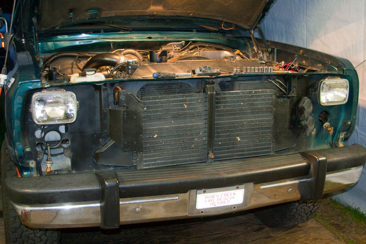
- Remove AC & intercooler stuff. Federal law compels us to recover the AC refrigerant OK? With the refrigerant in a bottle, I simply disconnected the line-set from the condenser coil with removing the one bolt. I Ty-rapped a sandwich bag over the open plumbing so as not to get trash in there.
- Remove the Fan and it's shroud. When storing the fan/clutch assembly, be sure to stand the assembly up-right so as not to allow the silicone fluid to leak out. Remember the fan/clutch mounting is reverse threaded.
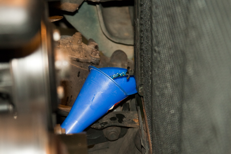
Now drain the engine coolant from the radiator saving it in a pail for reuse. If you're not gonna reuse it, be sure to dispose of it properly.
- Now remove the radiator keeping up with the two rubber vibration isolators found on the bottom of the radiator.
- Go pee and freshen-up your tea.
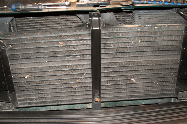
Now we need to cut the center radiator support column so there will be room to withdraw the cam and gear from the block.
The column is made from two layers of sheet metal. One nested in the other and spot-welded in place.
My thinking was to try to not cut things so much that reassembly would be a mess. With that . . .
Be sure to cover the face of the engine so you don't get any metal shards in anything!
- I cut the top of the column just above where it Y's out. I only cut the outer flanges so that I could bend the thing to do my work, and then bend it back when done.
- I cut the bottom of the column about an inch above where it meets the bottom of the radiator support assembly.
- DON'T bend the column out of the way just yet.
- Remove the front of the truck. Be sure to keep all the fasteners sorted and in a secure place so as not to get lost or confused.
- Remove AC & intercooler stuff. Federal law compels us to recover the AC refrigerant OK? With the refrigerant in a bottle, I simply disconnected the line-set from the condenser coil with removing the one bolt. I Ty-rapped a sandwich bag over the open plumbing so as not to get trash in there.
- Remove the Fan and it's shroud. When storing the fan/clutch assembly, be sure to stand the assembly up-right so as not to allow the silicone fluid to leak out. Remember the fan/clutch mounting is reverse threaded.
Now drain the engine coolant from the radiator saving it in a pail for reuse. If you're not gonna reuse it, be sure to dispose of it properly.
- Now remove the radiator keeping up with the two rubber vibration isolators found on the bottom of the radiator.
- Go pee and freshen-up your tea.
Now we need to cut the center radiator support column so there will be room to withdraw the cam and gear from the block.
The column is made from two layers of sheet metal. One nested in the other and spot-welded in place.
My thinking was to try to not cut things so much that reassembly would be a mess. With that . . .
Be sure to cover the face of the engine so you don't get any metal shards in anything!
- I cut the top of the column just above where it Y's out. I only cut the outer flanges so that I could bend the thing to do my work, and then bend it back when done.
- I cut the bottom of the column about an inch above where it meets the bottom of the radiator support assembly.
- DON'T bend the column out of the way just yet.
Thread Starter
1st Generation Admin
Joined: Jan 2005
Posts: 4,601
Likes: 118
From: Buies Creek, NC
- Roll the engine over to top-dead-center of the compression stroke for cylinder number one. This will among other things, ensure all the crankshaft's rod throws will be out of the camshaft's way on removal. Use the timing pin to help ensure you're there.
- Now remove the valve-covers.
- Loosen all the valves so they are completely loose with the valve-springs unloaded.
- Starting in the middle of the engine and working your way out, first loosen the head bolts that go through the rocker arm pedestals. Then loosen the smaller bolts that hold the pedestals in place. I put the rocker-arm/pedestal assemblies in individually numbered freezer bags so as to keep them clean and sorted.
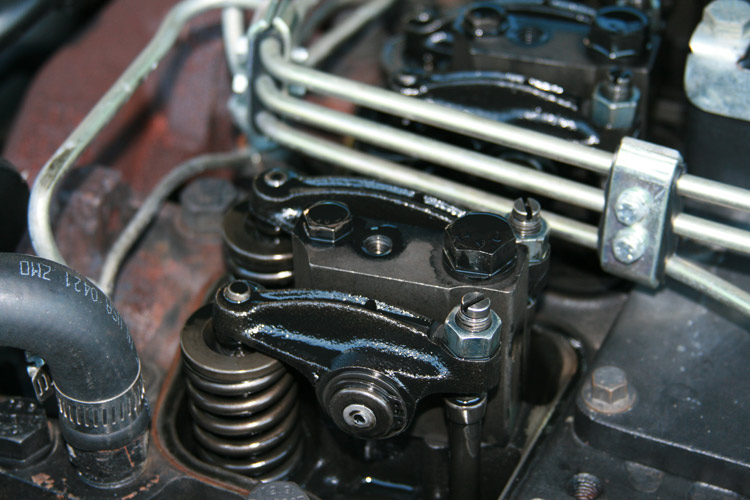
- Now remove the push-rods.
NOTE: If you're gonna reuse the push-rods and lifters, be sure to keep up with what push-rod goes where. You can use a piece of cardboard with two rows of six holes labeled "Intake" and "Exhaust" cylinder 1, 2, 3, etc.
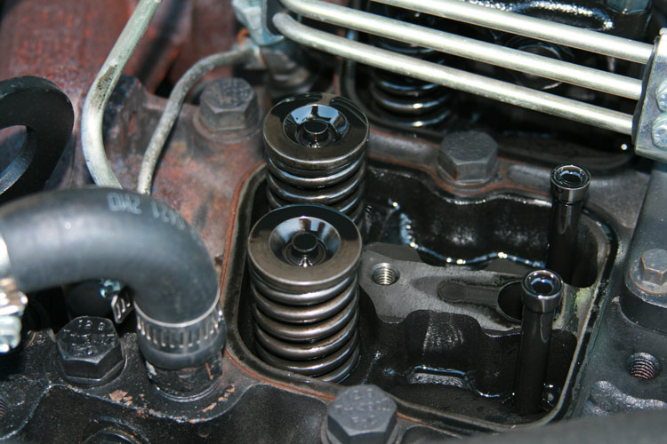
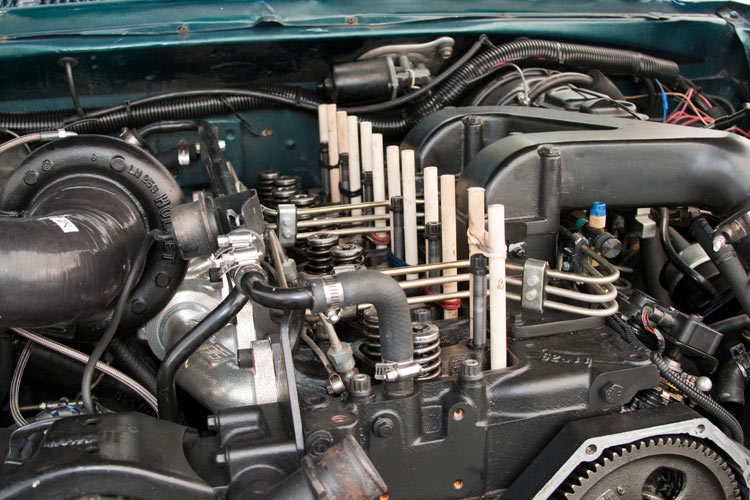
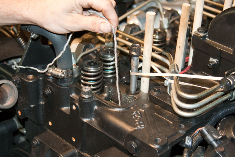
Now we need to lift the lifters up completely so the cam can be withdrawn without interference. The 12 Wooden Posts we made do that.
- Place one post per push-rod hole, cross-cut end first ensuring they are actually in the lifter.
- Now tap them fully into the lifter gently with a hammer.
- Lift each post up fully and using those hair bands, tie the posts to each other so they won't allow the lifters to slide back down onto the cam lobes.
- Remove fuel lift-pump.
- Remove the accessory serpentine drive belt.
- Remove the fan pulley from it's hub.
- Remove the crankshaft harmonic damper.
- Remove the gear-case cover.
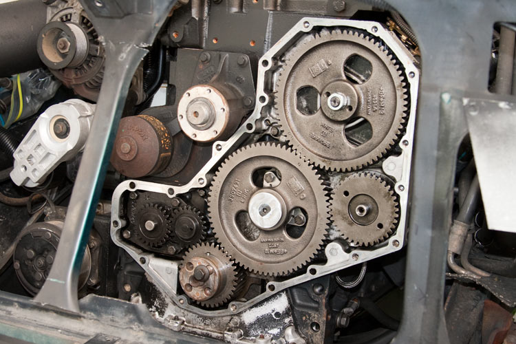
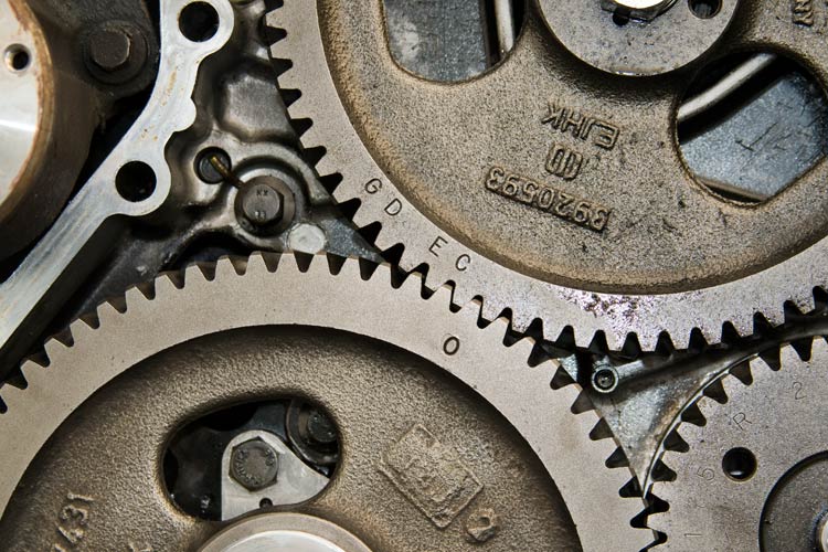
- Make note of the crank/cam indexing for reassembly.
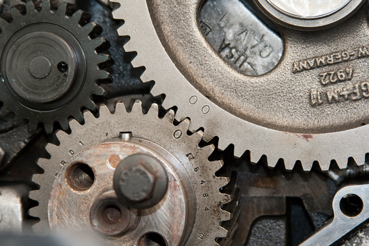
- Make note of the cam/IP indexing for reassembly.
- NOTE: Stock/OEM injection pump timing has the "O" of the camshaft gear go to the "E" of the injection pump gear.
Here, you can see I've got mine advanced two teeth.
- Now remove the valve-covers.
- Loosen all the valves so they are completely loose with the valve-springs unloaded.
- Starting in the middle of the engine and working your way out, first loosen the head bolts that go through the rocker arm pedestals. Then loosen the smaller bolts that hold the pedestals in place. I put the rocker-arm/pedestal assemblies in individually numbered freezer bags so as to keep them clean and sorted.
- Now remove the push-rods.
NOTE: If you're gonna reuse the push-rods and lifters, be sure to keep up with what push-rod goes where. You can use a piece of cardboard with two rows of six holes labeled "Intake" and "Exhaust" cylinder 1, 2, 3, etc.
Now we need to lift the lifters up completely so the cam can be withdrawn without interference. The 12 Wooden Posts we made do that.
- Place one post per push-rod hole, cross-cut end first ensuring they are actually in the lifter.
- Now tap them fully into the lifter gently with a hammer.
- Lift each post up fully and using those hair bands, tie the posts to each other so they won't allow the lifters to slide back down onto the cam lobes.
- Remove fuel lift-pump.
- Remove the accessory serpentine drive belt.
- Remove the fan pulley from it's hub.
- Remove the crankshaft harmonic damper.
- Remove the gear-case cover.
- Make note of the crank/cam indexing for reassembly.
- Make note of the cam/IP indexing for reassembly.
- NOTE: Stock/OEM injection pump timing has the "O" of the camshaft gear go to the "E" of the injection pump gear.
Here, you can see I've got mine advanced two teeth.
Thread Starter
1st Generation Admin
Joined: Jan 2005
Posts: 4,601
Likes: 118
From: Buies Creek, NC
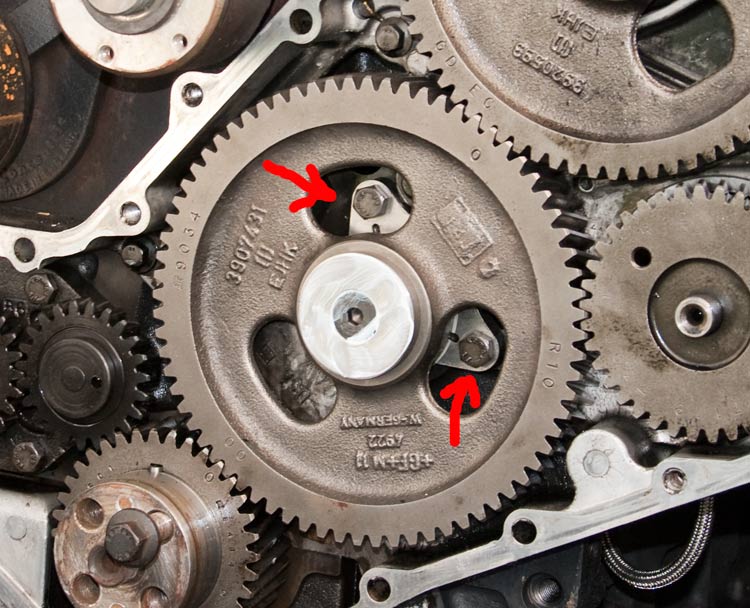
Other than ease of reassembly, we put the engine at TDC of cylinder no1 so that the holes in the camshaft gear, would uncover the two bolts that secure the camshaft's thrust-washer.
- Remove those two bolts.
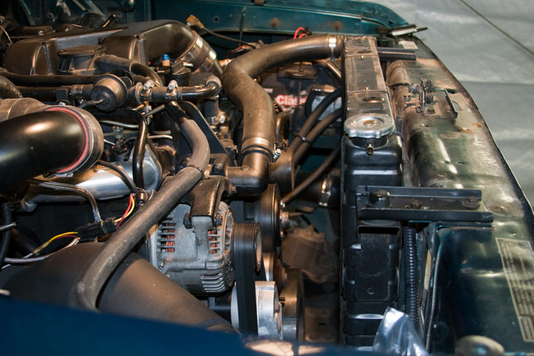
- Bend radiator support carefully forward just enough to clear the cam gear and no more.
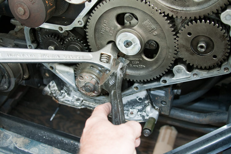
Y'all ever seen those spiffy little handles that can bolt onto a small-block Chevrolet camshaft? It makes it much easier to remove/install the cam.
Yeah, well, I haven't seen one for the Cummins mess.
- Get two large standard adjustable wrenches.
- Slip one wrench in the hole of the cam gear down there and have the wrench grip that lower cam gear web. Be sure the wrench is snug to the gear web.
- Now take the second wrench and have it grip the first wrench right there at the bottom of the wrench's jaw.
- Use the second wrench as a handle.
- With a gentle, twisting (counter clockwise) tug, pull the cam out of the block knowing that once the cam moves about 3/4 of an inch out, the camshaft's bearing surfaces are gonna drop out of the camshaft bearing bores.
- Be prepared to catch the camshaft's thrust washer as it falls out.
- Use the wrench handle mess to lift and hold the camshaft parallel to it's bore as you withdraw it.
- Use care so as not to ding the camshaft bearing surfaces along the way.
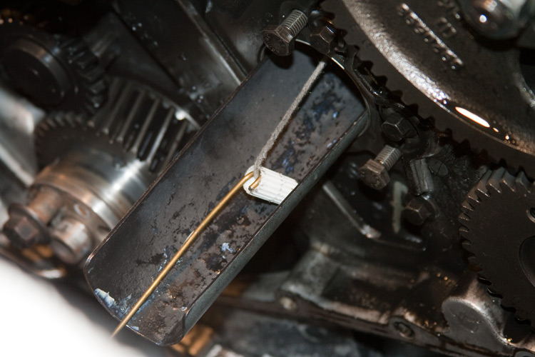
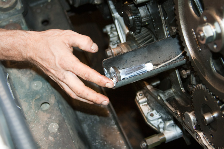
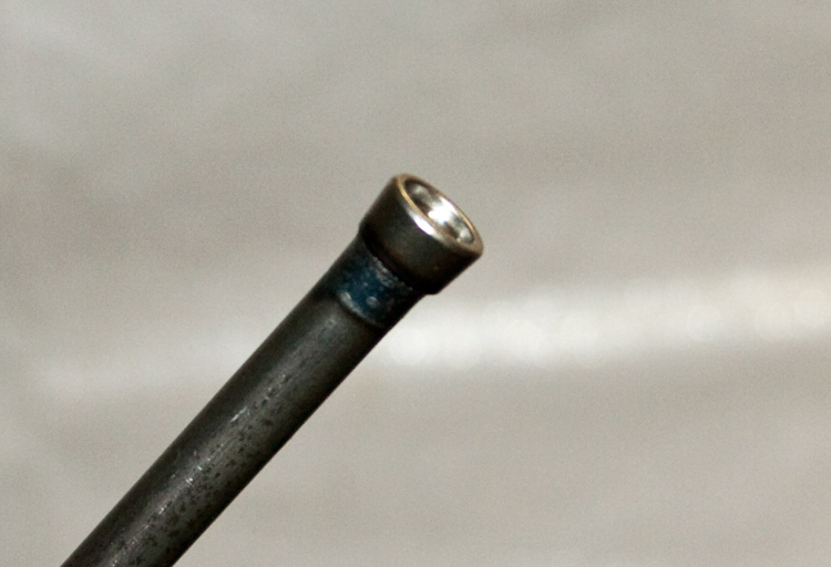
- Hold the Trough up next to the camshaft with the end-wall at the cam gear. Mark the Trough where the cam ends. See warning below.
- Lubricate the exterior surface of the lifter Trough with Lubriplate 105 or its equivalent up to the mark you made.
- Carefully slide the Trough into the block (end-wall first). You may have to twist it as you go, wiggling it up past each bearing journal.
WARNING! When inserting the Trough, pay attention when the mark on the Trough approaches the block. DO NOT allow the Trough to bang the cam bore freeze-plug at the back of the block. Doing so invites an oil leak at best. Worst case is you knock the plug out. Either way, repair has you pull the engine, or drop the trans.
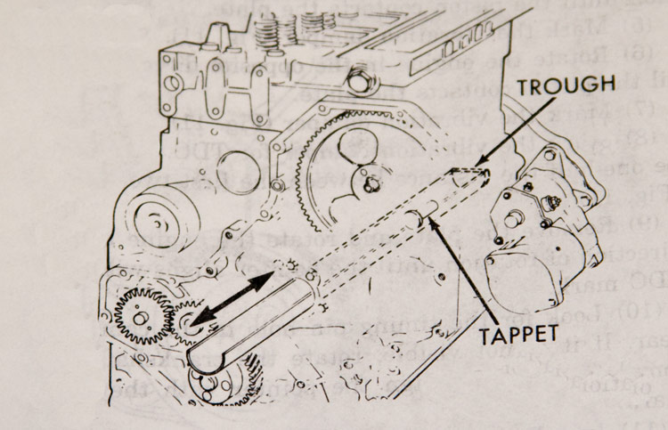
With the Trough in place we can now start removing the lifters.
- Starting with cylinder no1, remove the hair-band from the Wooden Post holding the intake valve's lifter. The lifter should drop into the Trough. If it doesn't, you can help it with the Wooden Post.
- You may need to gently rock the Trough a little to get the lifter to fall over.
- Remove the lifter from the Trough with your Hook-Tool. If you have difficulty with the coat-hanger, just slide the Trough out of the block enough to fetch it. Don't bang the freeze-plug sliding the Trough back in.
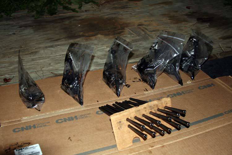
- If you plan to reuse your lifters, store them in the order of removal so you'll know which goes where.
- Continue till all the lifters are removed.
NOTE: Don't get all cocky and inadvertently let cylinder no6's exhaust lifter fall over the rear wall of the Trough! Be sure the Trough is fully inserted first.
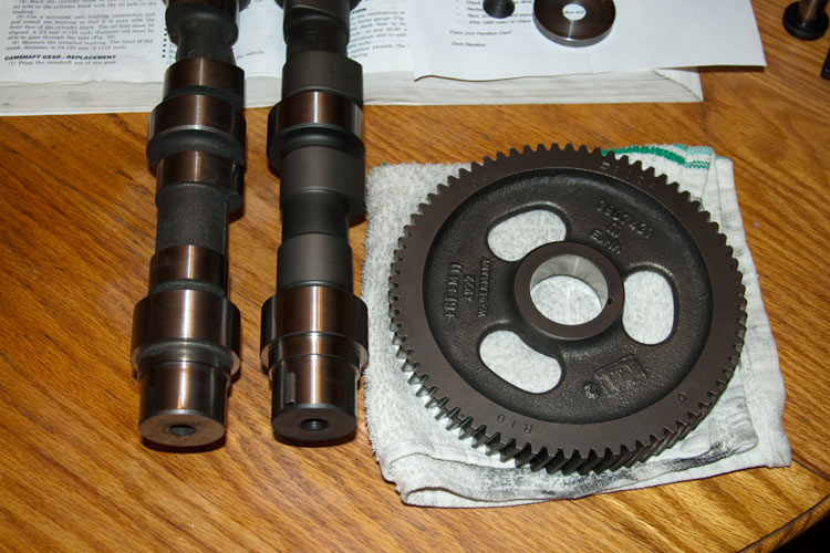
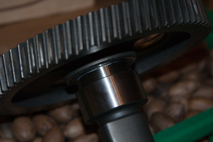
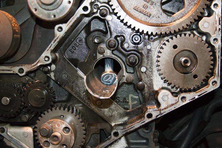
- Now, if you're gonna swap in a new camshaft or need to replace the cam gear, the two need to be separated.
- Some may suggest simply smacking things with a hammer. I used a press to do the work. The two are machined such that there's an Interference Fit so the gear's on there, but not like welded on there.
- Be sure to keep up with the key that locks the two as you'll need it when putting it all back together.
- Clean both the gear and cam snout being sure to remove any burrs.
In my application, I swapped in an aftermarket cam (right).
- Preheat your oven to 250*F ~ 300*F for 30 minutes. Check the actual temperature ensuring it goes no higher than 250*F ~ 300*F. Never allow the oven temperature to go above 350*F.
- Make sure the gear's clean so you don't stink-up Momma's kitchen!
- Place the gear in the center of the oven. Set it so the face of the gear looks up (Timing marks up).
- Heat the gear for 45 minutes. Never allow the oven temperature to go above 350*F.
- While the gear is heating, gently tap the key back into the camshaft's key-way. Set it so the forward edge is just slightly lower than the rear. That will aid in getting the cam gear on without it snagging the key.
- Apply a light film of Lubriplate to the camshaft snout.
- Have the camshaft securely held gear snout up, with the other end on the floor. Be sure not to mar the cam surfaces.
- After 45 minutes of heating, with protective gloves on, remove the gear from the oven and hold it over the camshaft snout. Look though the bore of the gear to visually align the key-way of the gear with the camshaft key. Install the gear on the cam snout ensuring the gear is fully seated to the camshaft shoulder.
- Allow the gear to cool and if you're not gonna reinstall the cam right away, lubricate the cam lobes and bearing journals to prevent rust.
- Remove those two bolts.
- Bend radiator support carefully forward just enough to clear the cam gear and no more.
Y'all ever seen those spiffy little handles that can bolt onto a small-block Chevrolet camshaft? It makes it much easier to remove/install the cam.
Yeah, well, I haven't seen one for the Cummins mess.
- Get two large standard adjustable wrenches.
- Slip one wrench in the hole of the cam gear down there and have the wrench grip that lower cam gear web. Be sure the wrench is snug to the gear web.
- Now take the second wrench and have it grip the first wrench right there at the bottom of the wrench's jaw.
- Use the second wrench as a handle.
- With a gentle, twisting (counter clockwise) tug, pull the cam out of the block knowing that once the cam moves about 3/4 of an inch out, the camshaft's bearing surfaces are gonna drop out of the camshaft bearing bores.
- Be prepared to catch the camshaft's thrust washer as it falls out.
- Use the wrench handle mess to lift and hold the camshaft parallel to it's bore as you withdraw it.
- Use care so as not to ding the camshaft bearing surfaces along the way.
- Hold the Trough up next to the camshaft with the end-wall at the cam gear. Mark the Trough where the cam ends. See warning below.
- Lubricate the exterior surface of the lifter Trough with Lubriplate 105 or its equivalent up to the mark you made.
- Carefully slide the Trough into the block (end-wall first). You may have to twist it as you go, wiggling it up past each bearing journal.
WARNING! When inserting the Trough, pay attention when the mark on the Trough approaches the block. DO NOT allow the Trough to bang the cam bore freeze-plug at the back of the block. Doing so invites an oil leak at best. Worst case is you knock the plug out. Either way, repair has you pull the engine, or drop the trans.
With the Trough in place we can now start removing the lifters.
- Starting with cylinder no1, remove the hair-band from the Wooden Post holding the intake valve's lifter. The lifter should drop into the Trough. If it doesn't, you can help it with the Wooden Post.
- You may need to gently rock the Trough a little to get the lifter to fall over.
- Remove the lifter from the Trough with your Hook-Tool. If you have difficulty with the coat-hanger, just slide the Trough out of the block enough to fetch it. Don't bang the freeze-plug sliding the Trough back in.
- If you plan to reuse your lifters, store them in the order of removal so you'll know which goes where.
- Continue till all the lifters are removed.
NOTE: Don't get all cocky and inadvertently let cylinder no6's exhaust lifter fall over the rear wall of the Trough! Be sure the Trough is fully inserted first.
- Now, if you're gonna swap in a new camshaft or need to replace the cam gear, the two need to be separated.
- Some may suggest simply smacking things with a hammer. I used a press to do the work. The two are machined such that there's an Interference Fit so the gear's on there, but not like welded on there.
- Be sure to keep up with the key that locks the two as you'll need it when putting it all back together.
- Clean both the gear and cam snout being sure to remove any burrs.
In this "How-To", it is assumed you're swapping in a new camshaft. If you plan on reusing your original camshaft, you'd do well to fully inspect it so as to be sure it's worth putting back in.
Camshaft and gear inspection
- Check the lift-pump lobe, valve lobes and bearing journals for cracking, pitting or scoring.
- Check the gear teeth for pitting. Check for cracking at the root of the gear teeth.
- Measure the lift pump and valve lobes at both the forward and rear edges.
INTAKE LOBE: 1.852" (47.040 mm) minimum.
EXHAUST LOBE: 1.841" (46.770 mm) minimum.
LIFT PUMP LOBE diameter (min): 1.398" (35.500 mm).
-> In addition to measuring the diameter of the cam bearing journals at the forward and rear edges, take a second measurement 90* from the first (making sure it's round).
CAMSHAFT JOURNAL diameter (min): 2.1245" (53.962 mm).
Pitting Reuse Criteria
- A single pit should not be greater than the area of a .079" (2 mm) diameter circle.
- Interconnection of pits is not acceptable and is viewed as one pit.
- The total pits, when added together, should not exceed a circle of 0.236" (6 mm).
- Only one pit is allowable within + or - 20 degrees of the nose of the cam lobe.
Edge deterioration (breakdown) criteria
- The area of edge deterioration should not be greater than the equivalent area of a 0.079" (2 mm) circle within + or - 20 degrees of the nose of the cam lobe.
- Outside of the + or - 20 degrees of the nose of the cam lobe, the areas of edge deterioration should not be greater than the equivalent area of a 0.236" (6 mm) circle.
- Preheat your oven to 250*F ~ 300*F for 30 minutes. Check the actual temperature ensuring it goes no higher than 250*F ~ 300*F. Never allow the oven temperature to go above 350*F.
- Make sure the gear's clean so you don't stink-up Momma's kitchen!
- Place the gear in the center of the oven. Set it so the face of the gear looks up (Timing marks up).
- Heat the gear for 45 minutes. Never allow the oven temperature to go above 350*F.
- While the gear is heating, gently tap the key back into the camshaft's key-way. Set it so the forward edge is just slightly lower than the rear. That will aid in getting the cam gear on without it snagging the key.
- Apply a light film of Lubriplate to the camshaft snout.
- Have the camshaft securely held gear snout up, with the other end on the floor. Be sure not to mar the cam surfaces.
- After 45 minutes of heating, with protective gloves on, remove the gear from the oven and hold it over the camshaft snout. Look though the bore of the gear to visually align the key-way of the gear with the camshaft key. Install the gear on the cam snout ensuring the gear is fully seated to the camshaft shoulder.
- Allow the gear to cool and if you're not gonna reinstall the cam right away, lubricate the cam lobes and bearing journals to prevent rust.
Thread Starter
1st Generation Admin
Joined: Jan 2005
Posts: 4,601
Likes: 118
From: Buies Creek, NC
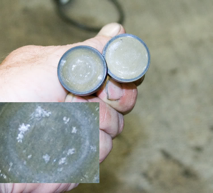
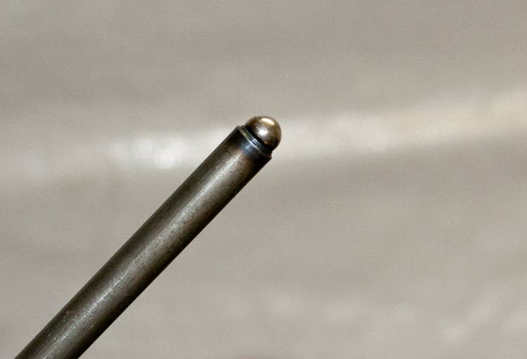
- Check the lifters socket, stem and face for excessive wear, cracks and other damage.
- The minimum lifter stem diameter is 0.627" (15.925 mm). If the stem wear exceeds that mentioned, replace the lifter.
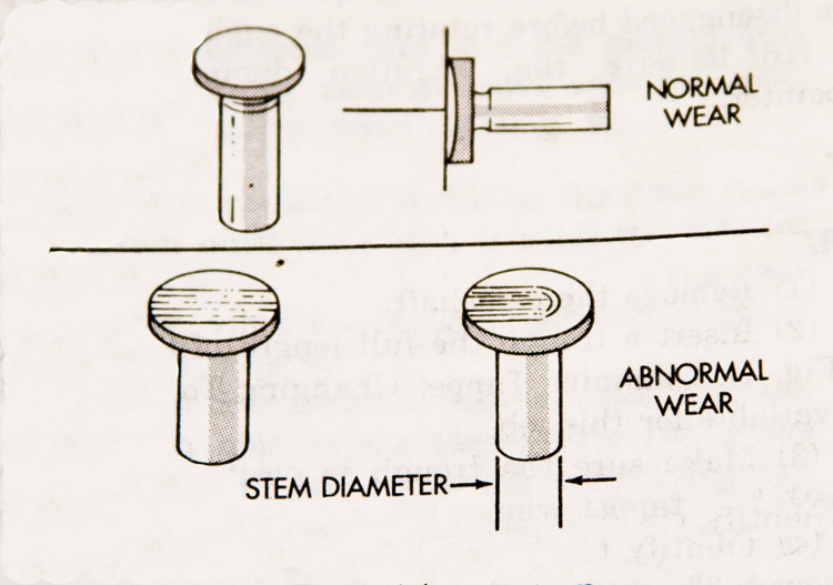
NOTE: In the case of abnormal wear or pitting (excluding excessive stem or socket wear), most lifters can be salvaged by resurfacing the face. Check with your favorite cam specialist.
Excessive pitting on the left, scoring on the right. Both fail but can be successfully resurfaced.
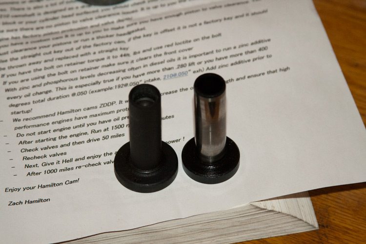
Alright, in MY application of installing an aftermarket camshaft, the new cam sports lobes that are substantially wider than OEM. The idea basically being that with the reduction of sulfur compounds in today's engine lube oil, accelerated wear of the load bearing surfaces is a problem. Increasing the surface area of those decreases the problem to a level today's oils can handle. Cummins did the same in today's newer engines.
To accommodate and make use of the new cam's wider lobes, I switched over to the wider 24v CTD lifters. They are wide enough to mate acceptably with the cam's wider lobes and still clear things like the lift pump's lobe without additional clearance.
Alright, if you're finished screwing around, let's put this mess back together.
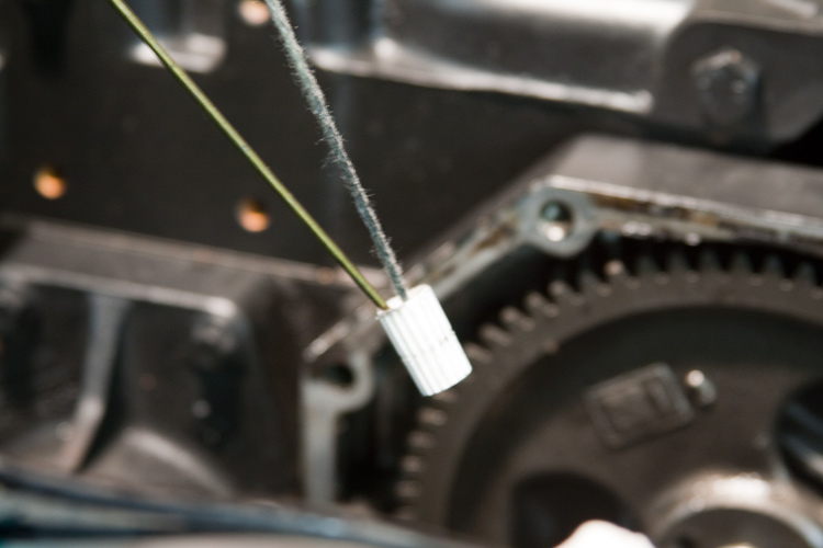
STOP! Test the Lifter Installation Tool. Gently press it into one of the lifters and get a feel as to how much pull it's gonna take to remove the tool from the lifter when the time comes. We don't want to inadvertently pull the string from the tool while the lifter's in the block.
With the Lifter Installation Tool in the lifter, dangle the assembly from the string and bounce the lifter around to get a feel as to how hard you need to press the tool in the lifter without it slipping out, and still be able to remove it when needed.
Okay?
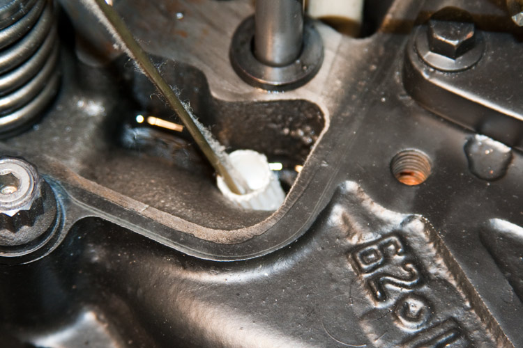
- Have the Trough fully inserted into the block, open end up.
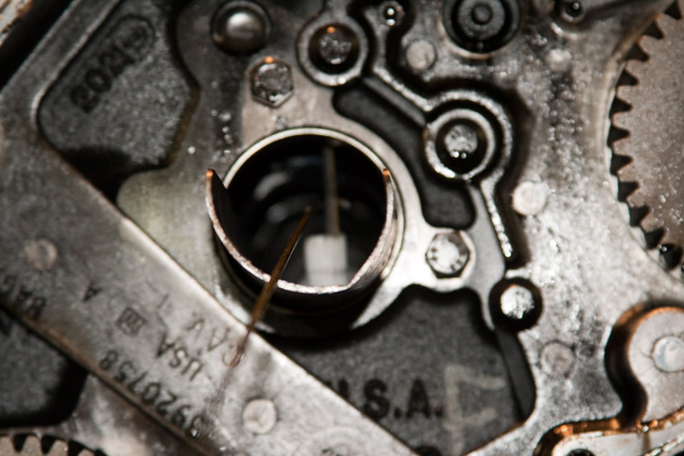
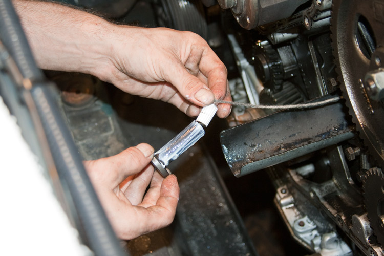
- Take the "L" shaped piece of coat-hanger and stick the long end into the Lifter Installation Tool you made. Hold the string tight. Like this . . .
- Use the L-tool to guide the Lifter Installation Tool through the push rod bore, through the lifter bore, and have the lifter tool rest in the Trough.
- Use the nifty Hooked coat-hanger tool to reach into the Trough and hook the string of the Lifter Installation Tool.
- Withdraw the L-Tool.
- Withdraw the Hook-Tool pulling the Lifter Installation Tool out with it.
- Liberally apply Lubriplate to the stem of the lifter.
- The minimum lifter stem diameter is 0.627" (15.925 mm). If the stem wear exceeds that mentioned, replace the lifter.
I've always believed that if you replace the camshaft, you need to be sure the lifter faces are absolutely pristine. If not, resurface or replace the lifters. As with the camshaft . . .
Lifter face pitting criteria
- A single pit can not be greater than 0.078" (2 mm).
- Interconnection of pits is not acceptable.
- Total pits when added together should not exceed 0.236" (6 mm) diameter or a total of 4% of the lifter face.
- No pitting is acceptable on the edges of the wear face of the lifter.
NOTE: In the case of abnormal wear or pitting (excluding excessive stem or socket wear), most lifters can be salvaged by resurfacing the face. Check with your favorite cam specialist.
Excessive pitting on the left, scoring on the right. Both fail but can be successfully resurfaced.
Alright, in MY application of installing an aftermarket camshaft, the new cam sports lobes that are substantially wider than OEM. The idea basically being that with the reduction of sulfur compounds in today's engine lube oil, accelerated wear of the load bearing surfaces is a problem. Increasing the surface area of those decreases the problem to a level today's oils can handle. Cummins did the same in today's newer engines.
To accommodate and make use of the new cam's wider lobes, I switched over to the wider 24v CTD lifters. They are wide enough to mate acceptably with the cam's wider lobes and still clear things like the lift pump's lobe without additional clearance.
Alright, if you're finished screwing around, let's put this mess back together.
STOP! Test the Lifter Installation Tool. Gently press it into one of the lifters and get a feel as to how much pull it's gonna take to remove the tool from the lifter when the time comes. We don't want to inadvertently pull the string from the tool while the lifter's in the block.
With the Lifter Installation Tool in the lifter, dangle the assembly from the string and bounce the lifter around to get a feel as to how hard you need to press the tool in the lifter without it slipping out, and still be able to remove it when needed.
Okay?
- Have the Trough fully inserted into the block, open end up.
- Take the "L" shaped piece of coat-hanger and stick the long end into the Lifter Installation Tool you made. Hold the string tight. Like this . . .
- Use the L-tool to guide the Lifter Installation Tool through the push rod bore, through the lifter bore, and have the lifter tool rest in the Trough.
- Use the nifty Hooked coat-hanger tool to reach into the Trough and hook the string of the Lifter Installation Tool.
- Withdraw the L-Tool.
- Withdraw the Hook-Tool pulling the Lifter Installation Tool out with it.
- Liberally apply Lubriplate to the stem of the lifter.
Thread Starter
1st Generation Admin
Joined: Jan 2005
Posts: 4,601
Likes: 118
From: Buies Creek, NC
- Press the Lifter-Tool firmly into the socket of the lifter.
- Liberally apply Lubriplate to the face of the lifter.
- Pull the Lifter Installation Tool's string to pull the lifter into the Trough and up to it's lifter bore.
- You may find the lifter occasionally stubborn in making the transition from laying in the Trough and up to it's bore (especially with the 24v lifters. The thinner wall Trough will give a little more room as compared to a PVC Trough). If so, rock the Trough back and forth a little to help the lifter make the transition. It may help to pull the Trough in and out a little.
- Pull the lifter up and completely into it's bore.
- Holding the lifter up in it's bore, rotate the Trough such that it's now upside down.
- Gently but firmly pull the Lifter Installation Tool from the lifter and engine.
- Reinstall one of the Wooden Posts and securely seat it in the lifter's socket.
- Secure the Wooden Post with one of the Hair-Bands.
- Rotate the Trough back to right side up and proceed with the next lifter's installation.
- Wipe the Lifter Installation Tool dry for the next use.

With all the lifters now back in the block, you can move on to preparing the camshaft for re-installation into the block.
- Check the torque of all the gear-case mounting bolts. They should be 18 ft/lbs. Back them out and set them again if you're not sure.
- Now's the time to address the so-called "Killer Dowel Pin" (KDP) if you haven't already.
- Liberally apply Lubriplate to the camshaft's bearing journals and lifter lobes as well as the slot right there at the cam gear where the thrust washer goes.
- Position the camshaft/gear assembly into the block as deep as you can by hand without beating up stuff along the way. Use the two adjustable wrenches to bring the assembly up to just before the final journal.
WARNING!! Do not allow the camshaft assembly to go any deeper into the block than the thrust washer would allow fearing knocking the camshaft bore's freeze-plug out.
- BE SURE THE TIMING MARKS ARE ALIGNED.
- Install the thrust washer.
- Lift/Push the Camshaft assembly into the block.
- Install and torque the thrust washer's bolts to 18 ft/lbs.
- Git a bea'ya and walk around for a few minutes loosening your back.
- Liberally apply Lubriplate to the face of the lifter.
- Pull the Lifter Installation Tool's string to pull the lifter into the Trough and up to it's lifter bore.
- You may find the lifter occasionally stubborn in making the transition from laying in the Trough and up to it's bore (especially with the 24v lifters. The thinner wall Trough will give a little more room as compared to a PVC Trough). If so, rock the Trough back and forth a little to help the lifter make the transition. It may help to pull the Trough in and out a little.
- Pull the lifter up and completely into it's bore.
- Holding the lifter up in it's bore, rotate the Trough such that it's now upside down.
- Gently but firmly pull the Lifter Installation Tool from the lifter and engine.
- Reinstall one of the Wooden Posts and securely seat it in the lifter's socket.
- Secure the Wooden Post with one of the Hair-Bands.
- Rotate the Trough back to right side up and proceed with the next lifter's installation.
- Wipe the Lifter Installation Tool dry for the next use.
With all the lifters now back in the block, you can move on to preparing the camshaft for re-installation into the block.
- Check the torque of all the gear-case mounting bolts. They should be 18 ft/lbs. Back them out and set them again if you're not sure.
- Now's the time to address the so-called "Killer Dowel Pin" (KDP) if you haven't already.
- Liberally apply Lubriplate to the camshaft's bearing journals and lifter lobes as well as the slot right there at the cam gear where the thrust washer goes.
- Position the camshaft/gear assembly into the block as deep as you can by hand without beating up stuff along the way. Use the two adjustable wrenches to bring the assembly up to just before the final journal.
WARNING!! Do not allow the camshaft assembly to go any deeper into the block than the thrust washer would allow fearing knocking the camshaft bore's freeze-plug out.
- BE SURE THE TIMING MARKS ARE ALIGNED.
- Install the thrust washer.
- Lift/Push the Camshaft assembly into the block.
- Install and torque the thrust washer's bolts to 18 ft/lbs.
- Git a bea'ya and walk around for a few minutes loosening your back.
Thread Starter
1st Generation Admin
Joined: Jan 2005
Posts: 4,601
Likes: 118
From: Buies Creek, NC
- Inspect the push rod ball for signs of scoring.
- Check for cracks where the ball is pressed into the tube.
- Inspect the push rod socket for signs of scoring.
- Check for cracks where the socket is pressed into the tube.
- Check to see if the push rods are round and straight by rolling them on a piece of glass.
- Lubricate both ends of the push rods with Lubriplate.
- Install the push rods in the engine making sure they are actually resting in the sockets of the lifters. They should come out of the lifter socket with something of a sucking feel when lifted. When you get them all in, stand back and look to see if one is standing tall compared to all the rest. If you see one or more, they probably aren't truly in the socket of their lifter. DO NOT proceed further until you're sure the push rods are properly seated in the lifters.

- Inspect the adjustable ***** of the rocker arm assemblies for scoring.
- Inspect the face of the rocker-arm where it meets the valve stem for scoring or other excessive wear. These can be refaced if need be.
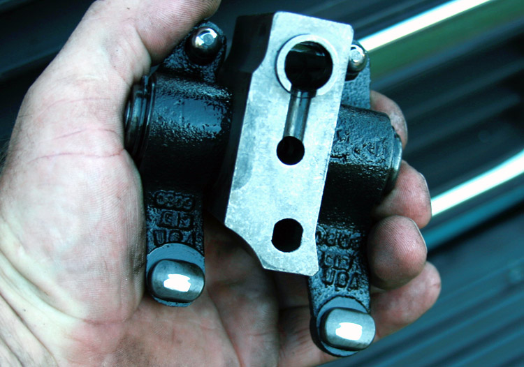
- Place each rocker-arm pedestal in it's proper location based on you're numbering of each when you initially removed them. Be sure the little ring around the head-bolt bore at the base of the pedestal is in fact nested in the head-bolt bore of the head.
- Lubricate each head-bolt with regular engine oil and bring up snug in the rocker arm pedestal.
- Install the smaller rocker-arm pedestal bolts and torque to 18 ft/lbs.
- Starting from the center of the head, bring the head bolts in the rocker-arm pedestals up to their proper torque. Refer to your truck's FSM for the exact procedure and torque values. (You may have the older, obsolete head-bolts, the newer ones or hi-tech studs. Figure it out).
- For now, if you're running the updated stock/OEM head-bolts, working from the center of the head out, bring the head-bolts first up to 66 ft/lbs. Check them again to be sure they are all there.
- Now bring them up to 89 ft/lbs. Again, check to see that they all are there.
- Now tighten them an additional 90*.

- Temporarily cover the top of the engine while you put the rest of the engine back together.
- Reinstall the fuel lift-pump. Torque those bolts to 18 ft/lbs.
- Again, if you've not addressed the so called "Killer Dowel Pin" (KDP), now's your last chance to do it before buttoning-up the engine.
- Install a new crankshaft seal in the gear-case cover. READ, UNDERSTAND AND FOLLOW the instructions when doing so to ensure no leaks.
- Using a new gasket, reinstall the gear-case cover. Torque those bolts to 18ft/lbs.
- Reinstall the engine cooling fan's hub. Torque those bolts to 7 ft/lbs.
- Reinstall the crankshaft vibration damper. Torque those bolts to 92 ft/lbs.
- Reinstall the serpentine accessory drive belt.
Now with the majority of the engine reassembled, go ahead and adjust the valves. You've already got the engine at TDC of cylinder no1 so. . . .
INTAKE (I): 0.010", EXHAUST (E): 0.020" -> Engine Cold <-
- Adjust cylinders 1 ~ I & E, 2 ~ I, 3 ~ E, 4 ~ I and 5 ~ E
- Now roll the engine over 360*.
- Adjust cylinders 2 ~ E, 3 ~ I, 4 ~ E, 5 ~ I and 6 ~ I & E
- Wipe clean the valve-cover bases and associated gaskets as well as the head's mating surfaces.
- Install the valve-covers and torque the bolts to 18 ft/lbs.
- Go pee and freshen your tea.
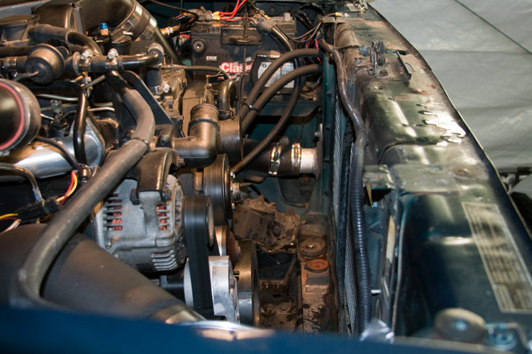
- Reassemble the radiator's center support brace. I used a piece of 1/8" thick sheet aluminum to make a strap that nests inside the original brace (engine side). I had it flair out like the brace at both the top and bottom. I then riveted it in place. Works just fine.
- Reinstall the radiator.
- Reinstall the inter-cooler.
- Reinstall the engine's cooling fan along with it's shroud. I put a booger of anti-seize on the fan clutch's hub threads to make it easier to remove in the future.

- Reinstall the front of the truck.
- Bleed any air from the fuel lift-pump plumbing.
- Fill the radiator with engine coolant.
- Reconnect the battery's negative cable.
- Start the engine and let it come to normal operating temperature while checking for any leaks. Repair as needed.
- If you put in a new cam follow the maker's break-in instruction including adding any recommended engine lube oil supplement. Else, check the valve adjustment again after letting the engine cool over night.
Y'all be safe and drive smart.
- Check for cracks where the ball is pressed into the tube.
- Inspect the push rod socket for signs of scoring.
- Check for cracks where the socket is pressed into the tube.
- Check to see if the push rods are round and straight by rolling them on a piece of glass.
- Lubricate both ends of the push rods with Lubriplate.
- Install the push rods in the engine making sure they are actually resting in the sockets of the lifters. They should come out of the lifter socket with something of a sucking feel when lifted. When you get them all in, stand back and look to see if one is standing tall compared to all the rest. If you see one or more, they probably aren't truly in the socket of their lifter. DO NOT proceed further until you're sure the push rods are properly seated in the lifters.
- Inspect the adjustable ***** of the rocker arm assemblies for scoring.
- Inspect the face of the rocker-arm where it meets the valve stem for scoring or other excessive wear. These can be refaced if need be.
- Place each rocker-arm pedestal in it's proper location based on you're numbering of each when you initially removed them. Be sure the little ring around the head-bolt bore at the base of the pedestal is in fact nested in the head-bolt bore of the head.
- Lubricate each head-bolt with regular engine oil and bring up snug in the rocker arm pedestal.
- Install the smaller rocker-arm pedestal bolts and torque to 18 ft/lbs.
- Starting from the center of the head, bring the head bolts in the rocker-arm pedestals up to their proper torque. Refer to your truck's FSM for the exact procedure and torque values. (You may have the older, obsolete head-bolts, the newer ones or hi-tech studs. Figure it out).
- For now, if you're running the updated stock/OEM head-bolts, working from the center of the head out, bring the head-bolts first up to 66 ft/lbs. Check them again to be sure they are all there.
- Now bring them up to 89 ft/lbs. Again, check to see that they all are there.
- Now tighten them an additional 90*.
- Temporarily cover the top of the engine while you put the rest of the engine back together.
- Reinstall the fuel lift-pump. Torque those bolts to 18 ft/lbs.
- Again, if you've not addressed the so called "Killer Dowel Pin" (KDP), now's your last chance to do it before buttoning-up the engine.
- Install a new crankshaft seal in the gear-case cover. READ, UNDERSTAND AND FOLLOW the instructions when doing so to ensure no leaks.
- Using a new gasket, reinstall the gear-case cover. Torque those bolts to 18ft/lbs.
- Reinstall the engine cooling fan's hub. Torque those bolts to 7 ft/lbs.
- Reinstall the crankshaft vibration damper. Torque those bolts to 92 ft/lbs.
- Reinstall the serpentine accessory drive belt.
Now with the majority of the engine reassembled, go ahead and adjust the valves. You've already got the engine at TDC of cylinder no1 so. . . .
INTAKE (I): 0.010", EXHAUST (E): 0.020" -> Engine Cold <-
- Adjust cylinders 1 ~ I & E, 2 ~ I, 3 ~ E, 4 ~ I and 5 ~ E
- Now roll the engine over 360*.
- Adjust cylinders 2 ~ E, 3 ~ I, 4 ~ E, 5 ~ I and 6 ~ I & E
- Wipe clean the valve-cover bases and associated gaskets as well as the head's mating surfaces.
- Install the valve-covers and torque the bolts to 18 ft/lbs.
- Go pee and freshen your tea.
- Reassemble the radiator's center support brace. I used a piece of 1/8" thick sheet aluminum to make a strap that nests inside the original brace (engine side). I had it flair out like the brace at both the top and bottom. I then riveted it in place. Works just fine.
- Reinstall the radiator.
- Reinstall the inter-cooler.
- Reinstall the engine's cooling fan along with it's shroud. I put a booger of anti-seize on the fan clutch's hub threads to make it easier to remove in the future.
- Reinstall the front of the truck.
- Bleed any air from the fuel lift-pump plumbing.
- Fill the radiator with engine coolant.
- Reconnect the battery's negative cable.
- Start the engine and let it come to normal operating temperature while checking for any leaks. Repair as needed.
- If you put in a new cam follow the maker's break-in instruction including adding any recommended engine lube oil supplement. Else, check the valve adjustment again after letting the engine cool over night.
Y'all be safe and drive smart.
Trending Topics

Registered User
Joined: Oct 2008
Posts: 1,591
Likes: 11
From: Thunder Bay
Wow this is quite possibly the longest how-to I've ever seen. I can't speak for anyone else but thanks so much for taking all the time to write this...
And thanks to whoever deleted my premature post. When I saw this posted I got a little too excited!
And thanks to whoever deleted my premature post. When I saw this posted I got a little too excited!

Thread Starter
1st Generation Admin
Joined: Jan 2005
Posts: 4,601
Likes: 118
From: Buies Creek, NC
Yes but with my tools, your young'un can color the instruction sheet with the high-liter while you do the work.
When you're done, you can rip down the wooden posts and using the colored instruction sheets, make a kite. You've got the string.

.
When you're done, you can rip down the wooden posts and using the colored instruction sheets, make a kite. You've got the string.
.
Registered User
Joined: Nov 2007
Posts: 1,816
Likes: 0
From: Maine
Thanks for giving me confidence in doing this. It looks so easy when I have something to reference in such detail as this. Can't wait to do mine when I yank the head to o-ring it.

Registered User
Joined: Aug 2006
Posts: 620
Likes: 0
From: Sioux Falls, South Dakota
