
Need help verifying TPS wiring

Thread Starter
Registered User
Joined: Oct 2008
Posts: 1,591
Likes: 11
From: Thunder Bay
Need help verifying TPS wiring
Ok, as most you know my motor is in a ford...
That said I am changing my TPS setup to the first gen one. The one that was in there before was ok, but I don't like it and the dodge one will work better for what I need.
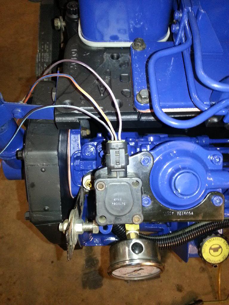
Anyway I need to know if I have this right, look at the pictures and verify this for me?
the wiring on my truck has the same setup as that last pic.
5V ref = r/w wire
TCU input (TPS output)= y/bl
ground = b/w
dodge TPS has
violet/white
black/blue
orange/blue
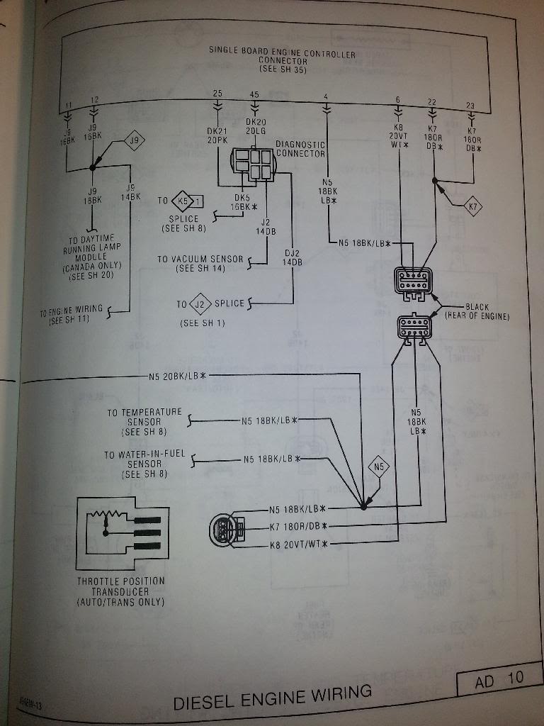
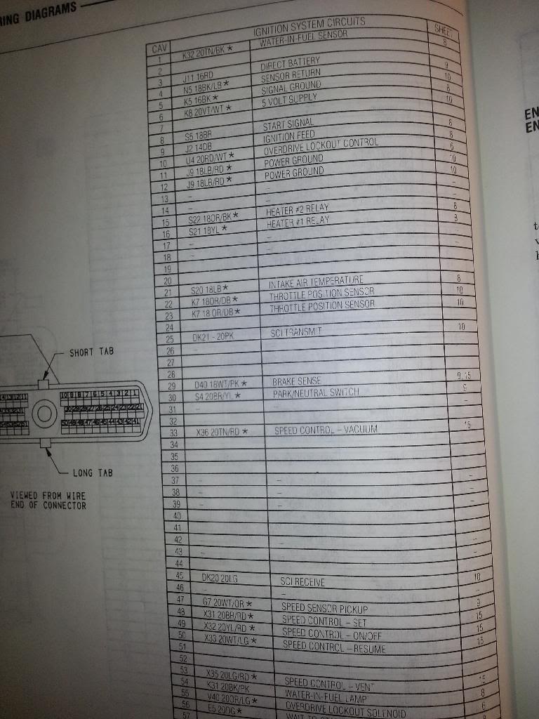
Now according to the diagram for my old dodge in pic 2 and 3 the dodge wiring is this
5V ref = violet/white (right wire in top pic)
TPS output/TCU input = black/blue (left wire in top pic
ground = orange/blue (middle wire in top pic)
Is that right?

That said I am changing my TPS setup to the first gen one. The one that was in there before was ok, but I don't like it and the dodge one will work better for what I need.
Anyway I need to know if I have this right, look at the pictures and verify this for me?
the wiring on my truck has the same setup as that last pic.
5V ref = r/w wire
TCU input (TPS output)= y/bl
ground = b/w
dodge TPS has
violet/white
black/blue
orange/blue
Now according to the diagram for my old dodge in pic 2 and 3 the dodge wiring is this
5V ref = violet/white (right wire in top pic)
TPS output/TCU input = black/blue (left wire in top pic
ground = orange/blue (middle wire in top pic)
Is that right?
Thread Starter
Registered User
Joined: Oct 2008
Posts: 1,591
Likes: 11
From: Thunder Bay
After some thought and study on the matter I have concluded with 95%certainty that In the pot fix threads it refers to the orange wire as the ref. Voltage but I think what is meant is that it is the signal/output voltage. The violet is the reference voltage aka the supply. Black is ground or return in the case of the last picture.
Can anyone more certain than me verify this? It makes the most sense to me
Set up in said configuration will have zero throttle around 1volt. And wot somewhere above 3.5 or so volts if configured/asjusted right on a first gen
Sent from Tapatalk 4 via a Galaxy S3
Can anyone more certain than me verify this? It makes the most sense to me
Set up in said configuration will have zero throttle around 1volt. And wot somewhere above 3.5 or so volts if configured/asjusted right on a first gen
Sent from Tapatalk 4 via a Galaxy S3
Registered User
Joined: Nov 2011
Posts: 4,479
Likes: 211
From: Isanti, MN
After some thought and study on the matter I have concluded with 95%certainty that In the pot fix threads it refers to the orange wire as the ref. Voltage but I think what is meant is that it is the signal/output voltage. The violet is the reference voltage aka the supply. Black is ground or return in the case of the last picture.
Can anyone more certain than me verify this? It makes the most sense to me
Set up in said configuration will have zero throttle around 1volt. And wot somewhere above 3.5 or so volts if configured/asjusted right on a first gen
Sent from Tapatalk 4 via a Galaxy S3
Can anyone more certain than me verify this? It makes the most sense to me
Set up in said configuration will have zero throttle around 1volt. And wot somewhere above 3.5 or so volts if configured/asjusted right on a first gen
Sent from Tapatalk 4 via a Galaxy S3
Now according to the diagram for my old dodge in pic 2 and 3 the dodge wiring is this
5V ref = violet/white (right wire in top pic)
TPS output/TCU input = black/blue (left wire in top pic
ground = orange/blue (middle wire in top pic)
Is that right?
5V ref = violet/white (right wire in top pic)
TPS output/TCU input = black/blue (left wire in top pic
ground = orange/blue (middle wire in top pic)
Is that right?
Orange/blue is the sensor out (wiper)
Violet/White is +5V from PCU
black/blue is ground from K4 splice

Thread
Thread Starter
Forum
Replies
Last Post
royta
2nd Gen. Dodge Ram - No Drivetrain
4
Apr 12, 2008 12:23 PM