Tools & Parts List
-
Transmission Fluid � 4 Quarts (8 quarts if you only lift the front of the vehicle.)
-
Funnel
-
Filter & Gasket
-
Floor Jack
-
Jack Stands � Capable of supporting vehicle in a raised position
-
Drain Pan � suggest one capable of holding 8 to 10 quarts fluid
-
Clean Rags
-
Gasket scraper or putty knife
-
Ratchet & extension
-
� inch socket
-
Torque Wrench
-
Screwdriver
-
#25 Torx head driver
-
Small amount of grease
-
Solvent
Note:
The front and rear bands should be adjusted at this time as well. Information on that procedure can be found in the Tech Faq section under �How do I adjust the bands on my 47RE�? http://www.dodge-diesel.org/faq/faq.php?display=faq&nr=24&catnr=4&prog=1&lang=en&onlynewfaq=1
Caution:
Transmission fluid can reach very high temperatures so only attempt this procedure after vehicle has had sufficient time to cool down completely.
-
With the vehicle parked on a solid flat surface, Raise and securely support the vehicle with jack stands.
-
Locate the drain pan under the transmission pan and remove the rear and side pan bolts, at this time only loosen the 4 front pan bolts 3 or 4 turns.

-
Using a screwdriver, carefully pry the transmission pan loose at the rear. This will allow the fluid to flow out of the pan. (Be certain to position yourself away from the pan as it can come out rather quickly.)
-
Slowly remove the front bolts and pour remaining fluid into drain pan.
-
Carefully using scraper or putty knife, clean all residues of gasket or sealant from transmission gasket surface.
-
 Remove the 3 torx head screws holding the filter to the Transmission valve body. (see illustration # 2) Carefully remove any gasket material
from the extremely delicate transmission valve body and replace with new filter and gasket. (Some filters come with the gasket attached to it.)
Note:
Rear transmission band adjustment bolt location is just inside of upper right hand corner of picture (out of view).
Remove the 3 torx head screws holding the filter to the Transmission valve body. (see illustration # 2) Carefully remove any gasket material
from the extremely delicate transmission valve body and replace with new filter and gasket. (Some filters come with the gasket attached to it.)
Note:
Rear transmission band adjustment bolt location is just inside of upper right hand corner of picture (out of view).
-
 Clean out bottom of transmission pan with solvent. Use a solvent like brake cleaner or paint thinner. The large round washer in the pan is a
magnet; it can be removed and cleaned thoroughly before replacing. The magnet catches the small metal particles associated with normal wear. As
well as larger pieces that might indicate a potential problem.
Clean out bottom of transmission pan with solvent. Use a solvent like brake cleaner or paint thinner. The large round washer in the pan is a
magnet; it can be removed and cleaned thoroughly before replacing. The magnet catches the small metal particles associated with normal wear. As
well as larger pieces that might indicate a potential problem.
-
Carefully remove all traces of the transmission pan gasket from the pan and clean thoroughly.
-
Place the new gasket on the transmission pan-mounting surface. Do not use a gasket sealer! A small amount of grease may be used to help hold the gasket in place.
-
Holding the pan and gasket against the transmission carefully start each bolt through the pan and gasket into the transmission. Moving in a circular direction around the transmission pan. slowly tighten the bolts a few turns at a time until just snug.
-
Torque the transmission pan bolts to 13 pounds using the same circular technique to assure even fit.
-
Lower the vehicle and using a funnel, pour approximately 3 to 3 � quarts of transmission fluid into the transmission filler tube. (If you only raised the front of the truck you will need to use more fluid. (My 4x4 drains out about 7 to 7 � quarts if I only raise the front of the vehicle to drain.)
-
Making certain parking brake is set and transmission is in park, run engine at a fast idle speed. Do not race the engine!
-
Holding down the brake, move the gear selector from park through each range and back several times.
-
With the transmission in Park check the fluid level, you will probably need to add a little to bring the level into the �Safe� zone on the dipstick.
-
Look under the vehicle for leaks and Pay particular attention to the level on the dipstick after the first few times you drive it. Also it wouldn�t hurt to recheck the torque on the Transmission pan bolts after a month or so of use. Sometimes the gasket will draw up a little and this will ensure you have no leaks.
Note: Front band adjustment bolt is located on left side of transmission (shown in center of picture)

*******************************
The choice that ATS has been installing has been the
new Standadyne Fuel Manager lift pump. This unit will
flow 6-10psi with the spin on filter from 5-30 micron
filter with a water separator option. We also found
out that the pump has a fuel warmer option as well. It
works well for people that live were its cold. We
built a kit that gives you the line hook ups and
relays to support the pump system. We mount the pump
between the frame and factory lift pump. This will
push the fuel to the factory system and warm the fuel
if needed. This gives better filtering of the fuel
before the factory pump and filter. We feel it will
also prolong the VP44 pump with cleaner fuel. We also
mount it inside the cross member and skid plate for
road protection.
For more information visit:
http://www.atsdiesel.com
http://www.stanadyne.com
You can also call Don Ramer from ATS at:
(303) 431-7973
Thanks Don Ramer ATS Diesel Performance
Many have found that correcting the output voltage from the APPS sent to the PCM has increased the throttle response, and boost. This calibration also adjusts the APPS for wear.
Instructions:
Tools: Digital Volt Meter, T-20 Torx bit, #1 phillips, 10mm socket
With the key on, engine off you need to probe the APPS wire to see where the voltage is currently set at.
The best location to probe the wire is on the PCM (Power Control Module) which is located on the passenger firewall behind the air intake.
You want the C1 connector, this is the connector closest to the engine
You want the orange wire with a dark blue tracer which is pin #23 (Please use a suitable backprobing adapter for your meter lead, do not pierce the insulation as this can lead to water intrustion/corrosion.)
Voltage should be somewhere around 0.5 volts,
At this point the voltage reading does not matter, it just has to be accurately written down for later reference
TURN THE IGNITION OFF ON THE TRUCK
Remove the black plastic cover off of your APPS. There are two plastic screws. One on the top and one on the front facing the radiator. It takes a little prying to pull it off.
Undo the 6-10mm bolts that hold the bracketry in place but DO NOT REMOVE THE CABLES!!
You will notice the APPS is on the back of the bracketry that you just removed, it is held in place by 2-T20 torx bit screws. These screws have a little bit of locktite on them so make sure you have a good socket and gently give a little tap with a hammer before attempting to loosen. Be very careful because these screws strip VERY easily and you only get one shot at them (VERY VERY VERY IMPORTANT; They are VERY tight).
On the APPS you will find a white tag that gives you the information on what the APPS voltage should be.
After loosening the screws (do not remove) you can rotate the APPS clockwise or counter clockwise to get the adjustment (towards the front of the truck increases voltage and towards the rear of the truck decreases voltage)
The reading you took at the beginning of the process on pin #23 should match the white tag on your APPS. If it doesn't the adjust accordingly.
First off, the name "lift pump" is just exactly what it impies. It's job is to supply pressurized fuel to the main injection pump. Keep in mind that the main injection pump does not require gallons of fuel to run. If you examine the line from the lift pump to the injection pump, you will find it to be about a 5/16 steel line. By the size of the line, you will know that not much flow occurs. (how much flow can you get out of a 5/16 line in a minute?) Actually, it's less than a gallon. I looked in the Cummins troubleshooting manual for the 5.9 engine. The requirement of a good fuel pump is to flow fuel at a rate of .70 gallons a minute into a bucket for a test. the actual pressure is less than I expected. Cummins says it should put out 3-5 psi during the test. As the main injection pump has the job of metering fuel to the injectors, increasing the lift pump pressure and supply does NOTHING to the performance of the engine --- providing that the lift pump is supplying .70 gal a minute at 3-5 psi. Keep in mind that these are minimum specs. If the fuel pump dosen't pass this test, then the pump is bad and it WILL affect the power output of the engine. Knowing these specs of .70 gal per minute at 3-5 psi, we can select an aftermarket fuel pump if necessary because of money. The cheapest way to buy an original fuel pump is through the Cummins parts dealers. Buying one from the Dodge dealership is costly. I understand that Cummins will sell a pump for at least $100, Dodge I understand is a lot higher. Suprising thing, gasoline electric aftermarket fuel pumps are very capable of supplying fuel in greater amounts (.70 gpm) and higher pressure than 3-5 lbs. This makes them capable of performing a "lift pump" function. Many electric gasoline fuel pumps can be purchased from $30 to $70 that will work in place of the more costly Cummins item. The only requirement is to hook the pump to the ignition side of the ignition switch and block off the hole where the old fuel pump is removed from the block with a steel plate and some gasket material. The added advantage of an electric fuel pump is the ease of priming the fuel system. Should you change fuel filters or lines, all you have to do is turn on the ignition and bleed the fittings without cranking the engine. Of course adding a electric fuel pump requires some modification and it is easier just to replace the lift pump if you so desire. The choice is yours to be made. The main idea of this article is to dispel the problems and myths of "lift pumps". It's job is actually quite simple. They are easy to diagnose if there is a problem. Just get a bucket and a fuel pressure guage to test it. The guage can be obtained from a autoparts store and is the same one that is used to test gasoline fuel pumps (0 to 20 psi range).
Happy troubleshooting
Article Written by Den052
1. Set parking brake
2. Disconnect negative battery cables on both batteries
3. Turn ignition key to run(to drain any remaining capacitors)
4. Let truck sit for 30 minutes( this is the recommended minimum)
5. Return ignition to OFF position
6. Reconnect both batteries and secure, not a timed event
7. Turn key to run position(not start) and depress accelerator pedal slowly all the way to the floor
8. Allow pedal to return to top position slowly
9. Turn ignition switch OFF
10.Release parking brake
47RE Front Band, left side of trans case on the outside:
Loosen locknut, back off 3-5 turns, ensure that the tork screw (older models 5/16 square head) turns freely in case. Apply lube to threads if necessary.
Tighten adj screw to 72 in lbs back off adjustment screw 2 - 2 1/4 turns. Hold adj screw and tighten locknut to 30 ft. lbs.
Band adjustments especially the front band are critical because of the Dodge shift pattern. A dodge trans shifts 1-2, back to 1st then into 3rd.
If the 2nd band does not release before the third gear clutches come on, you will have a bind up which will shorten the life of the transmission. I usually go a little looser than factory specs on this front band.
Depending on the circumstances i have backed off the band
up to 2 1/2 turns.
Bill K
47RE Rear Band, inside transmission next to valve body. It can be identified by the fact that there is only one lever with an adjusting screw and locknut. (right side) Loosen locknut, back off 5-6 turns, ensure that adj screw turns freely in lever. Tighten adj screw to 72 in. lbs., then back off 2.5-3 turns. Hold adj screw and tighten locknut to 25 ft. lbs.
TOOL LIST
Pan bolts to 13 lb ft
Filter- torx 25
Front bands- torx 30- wobbly and u-joint, 3+6�ext
¾� long wrench for jam nut
Rear bands- adjusting screw-1/4� 12 pt
9/16� wrench for Jam nut
Trans kickdown-39/1000 clearance, no delay from top to bottom. Be careful with clip. Use small screwdriver and pry up on each side of cable. Might not need adjustment, but see how it drives with your mileage.
Mike
Drain the filter housing and watch to keep diesel off starter. Disconnect power to pump, located on bottom.
To make the removal and installation easy take the 2 bolts(10mm) that hold the filter housing loose and moved the housing to the side, this makes it easier to get at the pump.
Then removed the 3 bolts(1/2) that hold pump to pump bracket,then removed one more bolt(10mm)that holds the supply line to the pump. With this being done you can move the pump around to finish removal easier.
Then remove the banjo bolt(11/16) that holds the supply line to the pump, be careful to get both washers.
On the opposite side of the pump coming from the filter housing is the last of the hoses, I opted to take the black hose off the pump, leaving the banjo bolt and fitting on pump.
Pull the old pump and clean all parts that will be reused(banjo bolts).
Attach banjo to the "out" side of pump with new washers and leave a little loose, Attach supply side banjo bolt to pump with new washers also, tighten up to specs.
Slide the new pump in and bolt all 3 nuts down tight, watch for clearance on "out" side against pump bracket.
Tighten down "out" side of pump to spec now.
Replace bolt that holds supply line to pump bracket and tighten.
Now you can attach power to the pump and clean up your mess, and yes you will have one .
Start it just like you would after filter install, might sputter for a second.
Cummins Lift Pump part #3990105
Price: $145.00
No special tools needed.
Procedure for a 1999 Ram
NOTE: You may be able to improve this but this is exactly what we did and changed two pumps in less that two hours)
TOOLS: 17 mm wrench & socket, 10 mm wrench & socket, 7/16 socket, ½ inch socket
*Lay a non-conducting material over the battery posts (fender cover, etc)
*Make sure you have the new pump and eight banjo washers
*Remove the two banjo bolts from top of the fuel filter housing using a 17 mm wrench
*Remove the old banjo washers from the fittings
*Disconnect the water in fuel sensor at the bottom of the fuel filter housing
*Disconnect the fuel filter heater element plug at top of the filter housing
*Remove the drain tube from the bottom of the filter housing drain
*Remove the two manifold bolts holding the filter housing to the intake manifold
*Remove the entire filter housing being careful not to drain the fuel from it
*Remove the banjo bolt holding the solid fuel line that goes the inlet of the filter housing using a 17 mm wrench
*Remove the banjo bolt on the suction side of the lift pump
*Remove the 10 mm bolt holding the suction line to the pump bracket
*Unplug the electrical connector to the lift pump
*Remove the three nuts holding the lift pump in place, ½ socket inch I believe
*Remove the lift pump
*Install the new pump and the two back nuts loosely just to hold the pump in place
*Install a new banjo washer on the suction bolt
*Install the bolt in the suction fitting and install another washer on the bolt
*Thread the bolt into the pump suction while the two nuts are loose on the pump
*Connect the power to the pump
*Install the cable support and the third nut on the pump bracket
*Tighten the pump suction banjo bolt, and the three nuts holding the pump in place
*Tighten the bolt holding the suction hose in place
*Install a washer on the pump discharge banjo bolt
*Install the bolt in the discharge tubing and install another washer
*Install the discharge to the pump but do not tighten
*Set the fuel filter housing back in place with the two manifold bolts but do not tighten
*Install a washer on the filter inlet banjo bolt
*Install the bolt far enough to get another washer on the other side and thread the bolt into the filter inlet
*Install a washer on the filter outlet banjo bolt
*Install the outlet banjo bolt in the outlet tubing and install another washer on the other side
*Thread the outlet bolt into the filter housing
*Tighten to two filter housing intake manifold bolts
*Tighten the two 17 mm inlet and outlet bolts on top of the housing
*Tighten the 17 mm bolt on the discharge of the lift pump
*Connect the fuel grid heater wiring at the top of the housing
*Connect the fuel in water wiring to the bottom of the housing
*Install the plastic housing drain tube
*Loosen the inner or outer plug on top of the housing with a 7/16 socket
*Bump the key like you are going to start the truck and bleed the system (may need to do this several times)
*Do a double check and make sure everything is tight and there are no leaks
By : jrs_dodge_diesel
Tools needed :
A set of feeler gauges
Open end wrenches 9/16 in or a 14mm, 10mm
Allen key set
Socket set 10mm, a 7/8 in or 22mm
Torque wrench
Inspection mirror
Optional tools
Cummins barring tool P/N 3377371
Flashlight
Specifications:
Rocker arm locknut 18 ft lbs
Intake valve - .010
Exhaust valve - .020
Valve Order
TDC Cylinder # 1 In + Ex, 2 In, 3 Ex, 4 In, 5 Ex
BDC Cylinder # 2 Ex, 3 In, 4 Ex, 5 In, 6 In+Ex
Procedure :
Engine must be cold prior to setting the valve lash. Overnight cool off is ideal.
1. Remove the valve cover. There are 5 bolts that hold the valve cover to the head. Use a 10mm socket wrench or nutdriver to loosen the bolts. You will not be able remove the bolt completely. After all 5 are loose pick up the cover and remove the cover. It can be tricky to remove. Be careful not to damage the rubber valve cover gasket.
2. Remove the injection pump drive cover. The cover is simply the round plastic piece that the breather tube connects to on the timing cover. Remove the breather tube from the cover. The cover simply screws onto the timing cover. Rotate counter clockwise to remove.
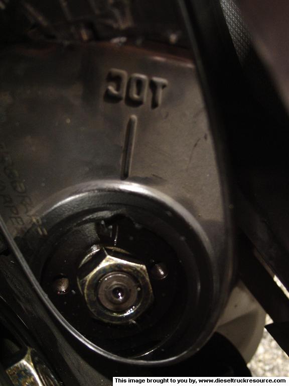
3. Rotate the crankshaft so that cylinder #1 is at Top Dead Center (TDC). This is accomplished with one of two ways:
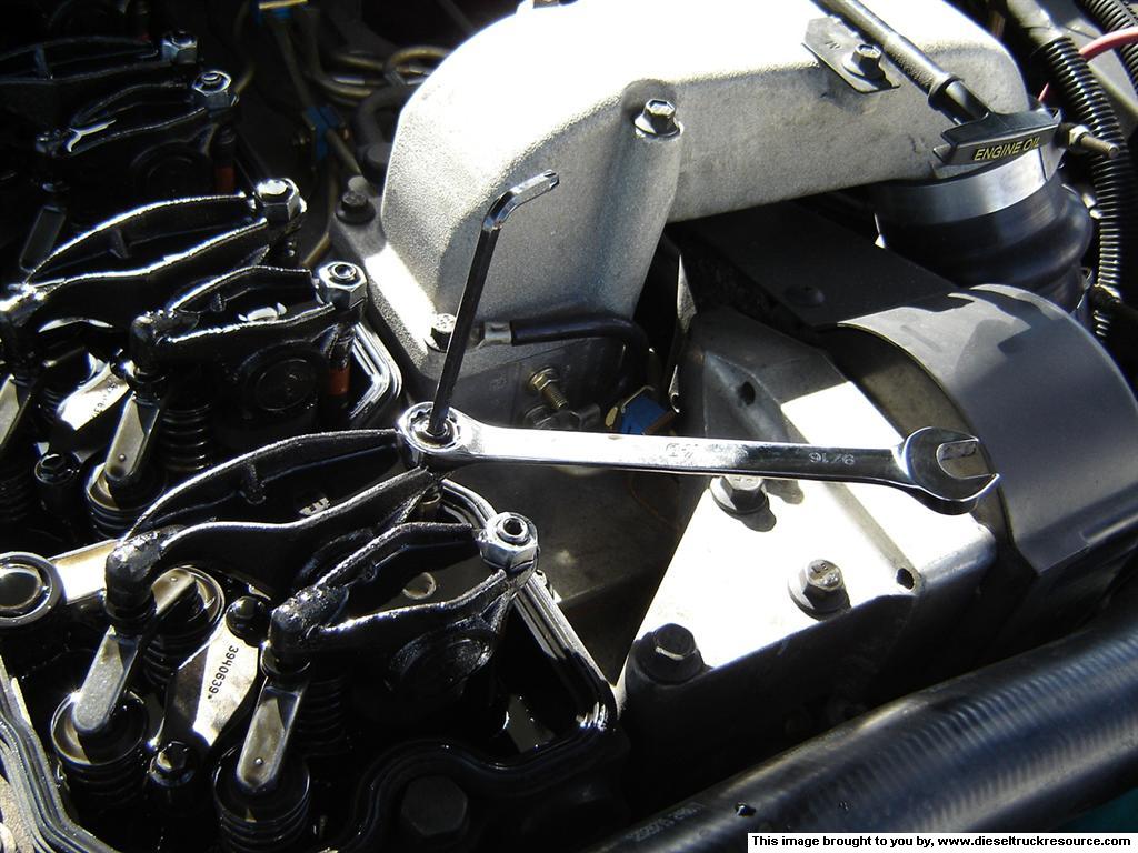
3a. One is by using the Cummins Barring tool and a 1/2 in drive. Remove the rubber plug on the front passenger side of the bell housing. Insert the barring tool and turn the wrench. This method engages the flywheel directly to rotate the crankshaft. You can rotate the crankshaft either direction.
3b. The other method uses the alternator nut to rotate the crankshaft via the belt. Use either a 7/8in or a 22mm socket on the alternator pulley nut. Turn the wrench counter clockwise. If you turn the wrench clockwise the pulley will slip and not turn the belt at all. This method turn the crankshaft backward from the direction it normally turns while running.
While using either of the two methods to rotate the crankshaft, you must watch the fuel pump drive gear to line up the timing marks (pictures below). There two markings on the timing case, one marked TDC and one marked BDC. Line up the timing mark on the drive gear with the TDC notch.
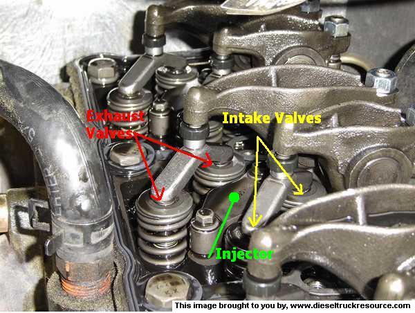
4. Setting the valves. Now that cylinder #1 is at TDC you can adjust some valve. Refer to the Valve Order listing to adjust the correct valves for TDC. Here you will need the open end wrenches, allen key set, feeler gauges, and the torque wrench. Start with cylinder #1. For reference the short rocker arm is for the intake valves, and the longer one is for the exhaust valves. (picture 1) The feeler gauge is used where the pivot stud meets the Y piece that engages the valves.
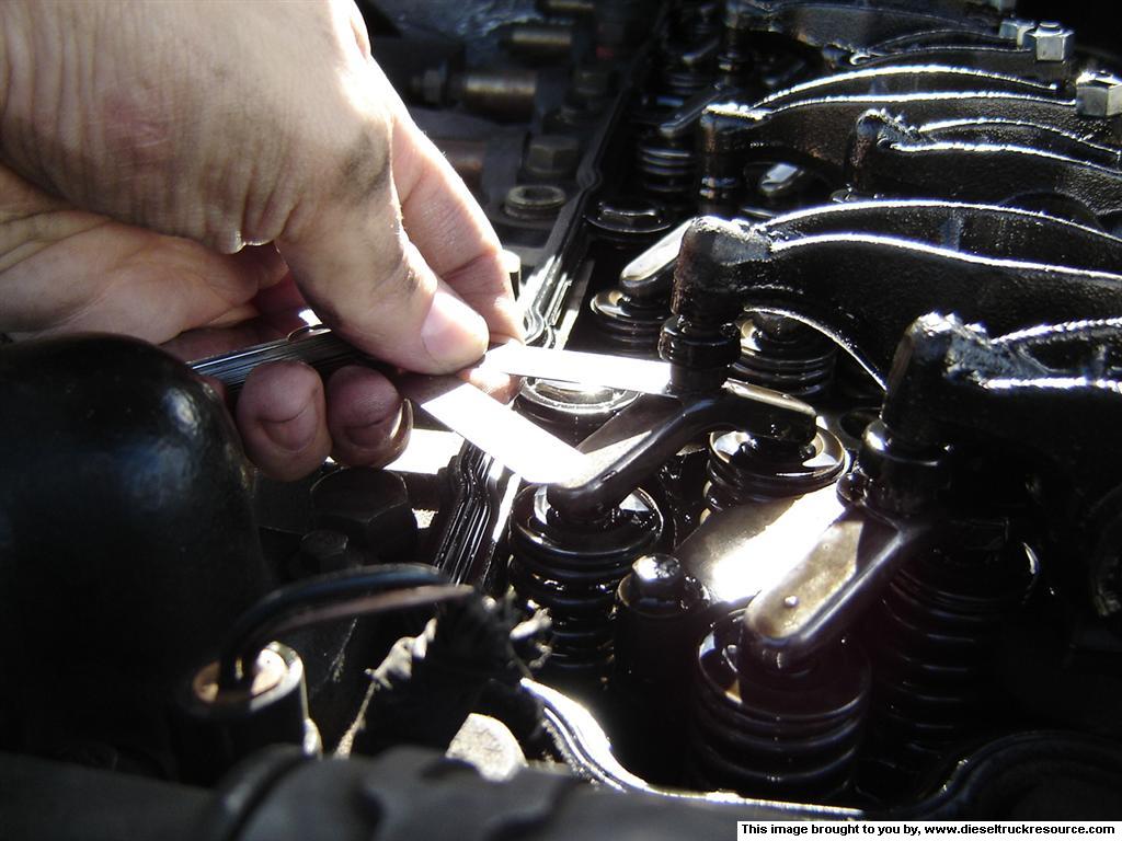
Loosen the locknut on the rocker arm. Insert the feeler gauge, (picture 2) remember to use the proper size, .010 for intake and .020 for exhaust. Now use the proper allen key and adjust the allen head screw in the middle of the locknut. (picture 3) This adjusts the gap (valve lash) between the pivot stud and the Y piece. You will feel a slight drag on the feeler gauge once the gap is set correctly. Then remove the feeler gauge and with two hands hold the allen key steady while tightening the locknut, this is the most tricky part of the procedure. After tightening check the valve lash again and adjust as needed.
Do all the valves listed in the Valve Order for TDC. After that is complete rotate the crankshaft one revolution until the timing mark is at the notch for BDC. Then do the valves listed for BDC.
Tips and Techniques
One great way to make sure of the proper valve measurement is to use what I call the Over Under technique. For example with the intake measurement of .010. A great way to know if you have the adjustment dead on is to use a feeler gauge that is .001 up and down from the intended measurement, so you would use a .011 and a .009 feeler gauge. When measuring the .009 gauge will fit very easily and the .011 gauge will not fit at all.
Another tip is after all adjustment is done to rotate the crank shaft 2 revolutions and check all measurements again. This gives the springs a chance to compress and move the valves.
After all valves are adjusted and checked replace the valve cover and the fuel pump drive cover and replace the breather tube.
By: Byron Nelson
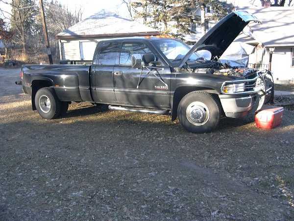
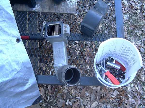
Here is the patient ready for the operation
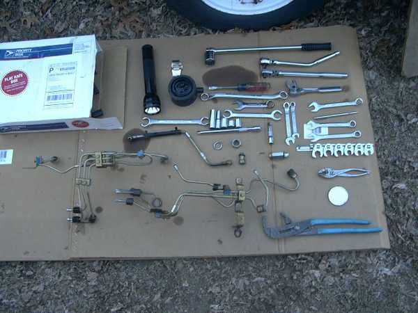
Here are the tools. We got a little ahead of ourselves so disregard the injector lines and the return line. Note the injector lines are in two groups of three and we did not remove or loosen the connecting clamps. The black round thing is the breather housing removed with the channel locks. The box contains a Vulcan lift pump relocate and big line kit. This is all of the tools we used. These tuck in a bag under the rear seat with spare oil filter and 2 fuel filters. Shown only in the first picture was the cooler we used to stand on. I leave it in the bed. It is a great carry all. I put the milk from the store in it, soda occasionally, and use it to stand on when waxing the truck.
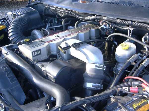
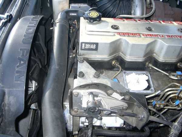
Under the hood ready to go
Here we have removed the air horn and grid heaters and the plastic cover over the apps sensor
Here is the air horn and grid heater and the plastic cover. Check the size of the wire on the grid heater!!! Bigger than a lot of battery cables.

Here we have removed the Apps sensor, the main fuel line, and the return line from the pump.
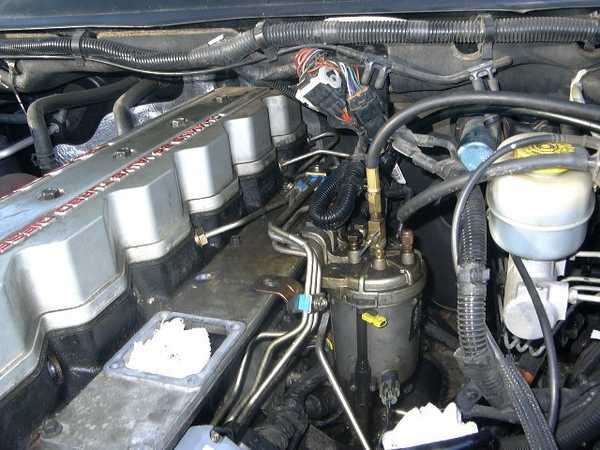
We have removed the first 3 injector lines, the bolt holding the rear injector lines, and the lifting lug at the rear of the intake manifold. You can clearly see the fuel pressure gage line and the needle valve and the banjo bolt on the fuel filter. It is a long ways back to the #6 injector line. This is where the 19mm crow foot, short extension and flop head ratchet are used.

This is not a good picture because it was taken through a mirror. Rotate the picture 90 deg CCW and you can see what the key and keyway look like after the nut and washer is removed from the front of the pump. You can clearly see the 8 mm screw holes in the pump gear. These are for the puller screws. The gear is quite large and you have to do something really bad to dislodge it, but, do be careful.

Here we are looking at the front of the old pump as it came out of the timing cover. You can see the key at about 10 oclock. Note the bracket on the bottom.

Again you can see the key in the shaft at the position it came out. Notice that the screws do not have any paint on them. This is an original pump with 163,000 miles on it. We were pretty sure that the electronic module failed and not the mechanical part of the pump.

The new VP-44 is installed. You can see the top 2 of the 4 nuts holding the pump on. It takes a long 3/8 extension to get at these. I used one of the extra short sockets from my serpentine belt install tool and a long wobble extension. We used heavy grease on the key and the o-ring. Worked great, the pump slid right in.

The rear injector lines are installed. Note that we did not remove or loosen the clamps holding the lines together. This made the re-install a lot easier.
The front lines have been installed and the line clamps are bolted down. #1,#3,#4 lines are slightly loose. You can not get at #2 with the air horn in place so tighten that one up.

Here is a top view of the pump with the lines installed.

The Apps is back on. The pump connector is plugged in. The return line is on and the main fuel line is on. We are almost done.
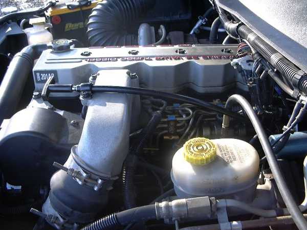
The air horn is back on, the dip stick is attached, the plastic cove is on and the intercooler boot is attached. We are ready to go!!
Summary
Replacing the VP-44
It was about 40 degrees out side so it was a little cool. We gathered the tools according to posts on DTR and laid them out on a big piece of card board. We went over to Harbor Freight and purchased a set of metric crowfoot line wrenches mostly for the 19mm one. We also went to Sears and got a combination wrench in stubby style, a 5/8 line wrench, a 24mm and a 27 mm 12 point drive sockets. Then we went over to Auto Zone and got the crankshaft position sensor and a steering wheel puller.
It would not be a bad idea to put a new camshaft sensor in too as they are about $45 -65 but entail removing the injector pump to install.
I got this pump from Midwest Fuel injection. Great to work with. I had it the next day and they didnt charge for the core charge for 30 days so you dont have to front that money. They also pay for return shipping.
I laid out all the tools again:
10mm 12 pt combination wrench
3/4 by 5/8 line wrench
12 pt stubby combination wrench
19mm crowfoot line wrench
24 mm 12 pt 1/2 drive socket
27 mm 12 pt 1/2 drive socket
set of metric hex drivers 3/8 drive
set of metric Torx drivers
set of metric sockets 12 pt 3/8 drive
set of metric deep wall sockets 12 pt 3/8 drive
socket set from a serpentine belt tool. These are optional but the sockets are 12 pt and ultra short. I used one of them to get at the injector pump to front cover nuts
8 inch 3/8 extension, a wobble extension is even better.
3 inch 3/8 wobble extension
3/8 standard ratchet
3/8 flop head ratchet
1/2 drive breaker bar.
Phillips screw driver
Standard screw driver medium
Steering wheel puller (straight)
Small mirror
Flash lite
REMOVING THE PUMP
Disconnect both batteries
Remove the dipstick tube bracket from the air horn
Remove the flex hose from the air horn to intercooler. Place a clean rag in it.
Remove the 4 bolts on the air horn and the nuts for the wires to the grid heaters.
Remove the air horn and grid heaters. Be careful of the gaskets so you can reuse them. Place a clean rag in the manifold opening
Remove the fuel line from the pump to the filter. Be careful of the gaskets.
Remove the fuel return line at the pump. Be careful of the gaskets
Remove the plastic housing over the top of the fuel pump.
Remove the bolts holding the APPS sensor on and swing it over to the fender. Best to tie it off with the dipstick.
Disconnect the 9 pin connector from the pump
Remove the injector lines 1,2,3 from the head. DO NOT REMOVE THE BRACKETS HOLDING THE LINES TOGETHER. Set these aside on your bench
Remove the matching line nuts from the injector pump.
Remove the engine lifting lug from the head.
Remove the injector lines 4,5,6 from the head. Here is where the 19mm crow foot line wrench is needed.
AGAIN DO NOT REMOVE THE BRACKETS HOLDING THE LINES TOGETHER.
Remove the injector lines 4,5,6 from the pump and set aside.
Remove the bracket at the rear of the pump that attaches to the block.
Remove the breather tube and housing. A strap wrench works well but muscle works too. It just screws into the front cover.
Bar the motor over using the 24 mm socket in the alternator. You can only turn the motor over one way and slowly. Use the mirror to watch for the line up marks on the pump gear. Align these so they are straight up or 12 oclock The key way must be at 12 oclock or you will drop the key into the gears. Dont do this!!!
Loosen the pump drive nut with the 27 mm socket. Its tight but not impossible
Remove nut and washer from the front of the pump. We stuck a small magnet against the pump shaft, then slid the nut and washer onto the magnet stem.
Install the small wheel puller using the bolts from the air horn. We had a hard time with these as there is thread sealant on the threads and it felt like the thread pitch was wrong. I think the gear in the motor had the threads very tight probably from heat treating the gear. Since these are for us mechanics to use and not for production they probably are not checked. The threads are the same but just tight. We finally used some soft bolts we had laying around. The puller will pop the shaft loose very easily.
Remove the puller
Remove the 4 nuts holding the fuel pump to the front cover. Use the long 3/8 extension on the lower 2
The pump is now loose but you must be very careful of the key in the pump shaft. Wiggle the pump until it breaks free. Its mounted on a dowel pin so the pump must go about 1/4 inch to the rear before you can turn it. Also be careful of the lower bracket so it doesnt get caught on anything. Slide it to the rear watching for the key. It will remain in the shaft if you dont bump it. Once the pump is clear you can set it aside. There is a bit of fuel in the pump so dont rest it on your lap until it is drained.
Roll the pump over and remove the lower bracket. (150 Torx) Inspect the bracket for cracks and damage. Replace it if necessary. This bracket is very important so dont
Clean everything up and get ready to finish up.
The new pump comes with a new key specific to the pump. It has markings on it so make sure they are in the correct direction. We removed the key and added some heavy grease to the slot to hold the key in place and some grease on the o-ring to aid in installing the pump. Some use super glue on the key, some use tape. The grease worked for us.
Installation.
Install the pump being very careful of the key. Use the mirror to get things lined up. The dowel pin will guide the pump in.
Install the 4 pump housing nuts loosely.
Carefully install the washer and nut on the pump and snug them up. Dont tighten yet
Tighten the 4 pump housing nuts.
Install the support bracket to the pump and the block. We got at them from below. The object is to tighten them evenly against the block and pump so there is no binding against the pump.
Now finish tightening the pump drive nut and washer. These are about 125 ft lbs
Reinstall the breather assembly.
From here it is the reverse of the disassembly.
Leave line 1, 3, and 4 slightly loose so you can bleed the air from the system at startup.
Once everything is installed and tightened up you are ready to go.
Make sure all the tools and other items are secure and out of the way before starting.
Hook up the batteries
Turn the key on and bump the start but do not start it yet. The lift pump should run for about 20-30 seconds. Do this 2-3 times to purge some of the air out of the system.
Now crank the motor. It should start firing in a couple turns or less. It will rumble and sound terrible. As it starts running, you will see fuel coming out of the loose lines. We shut it off at this point and tightened up all the lines. Upon restart it rattled and rumbled and blew out a dense cloud of smoke then after a minute or so it started smoothing out. With about 5 minutes it was idling fine. We let it run about 20 minutes before hitting the throttle at all. It responded great so we jumped in and went for a ride. It was like a new truck!!!
WHEN THE MOTOR STARTS , DO NOT HIT THE THROTTLE JUST LET IT RUN.
After the motor has warmed up be sure to retighten the injector lines. I got about 50 miles down the road and washed the motor and entire bottom of the truck in diesel. It took 2 stops before the lines were all sealed back up. A trip through the car wash cleaned up underneath, but there wont be any rust this year for sure. Be sure to clear the codes at this point.
If you have all the tools ready, you should be able to do this in 4 hours easy even on the ground outside. A good shop guy could do it in 2 hours and have time for a break.
OBSERVATIONS AFTER THE INSTALL
The truck began running very well immediately after I got on the road again.
I noticed a big improvement in low end torque. Where I used to slip the clutch a little on starting out, it now just moves out by itself. There is a marked improvement in power from 1200 to 1800 rpm. It always seemed like the turbo was taking its time spooling up in this range but not now. There were times when it would blow huge clouds of black smoke when accelerating mostly when it was wet and very humid. It doesnt do this anymore. The idle down just as you are coming to a stop is only about 100 rpm at most now where it was about 200 rpm before. Sometimes it is not even there now, usually when it is cold. It also doesnt drop rpm as quickly between gears so up shifting is much easier and quicker. Starting is much improved. It was taking about 2-3 turns of the motor to get started, now it doesnt get 1 turn even at 5 deg F.
Summary of a failing VP-44 according to my observations
Gradually slower starts even with good batteries and starter.
Hard starting when it is below 0 outside.
Gradual loss of power at low rpms
Gradual loss of MPG I had previously always gotten 20+ on trips. It gradually became harder to maintain this, finally getting down to about 16-17 even on easy trips.
Sometimes a gently rolling idle where it was dead smooth before.
Clouds of black smoke when briskly accelerating. It was very hard even to get a puff at any time when the pump was good.
The motor slowed down sharply when shifting up. Now it is easy to maintain rpm
I never noticed any dead pedal or limp mode but I did seem to get less power on occasion. It was so slight and gradual decline that I really didnt take serious note of it.
Today the truck runs a good as new. It starts instantly even when cold, I am back up to 20 mpg even with ULSF and winter grade, The idle is dead smooth, the power is way up and is doesnt knock as much plus I have some more tools to carry in the truck and knowledge in the head.

Peak Torque
505 lb-ft (from 1600 to 2700 rpm)
Advertised Power
245 hp @ 2700 rpm
Governed Speed
3200 rpm
24-VALVE TURBO DIESEL - AUTOMATIC & 5-SPEED TRANSMISSION
Peak Torque
460 lb-ft (from 1600 to 2700 rpm)
Advertised Power
235 hp @ 2700 rpm
Governed Speed
3200 rpm
24-VALVE TURBO DIESEL - GENERAL ENGINE DATA
Type
4-cycle in-line 6-cylinder
Aspiration
Turbocharged, charge air cooled
Bore & Stroke
4.02 in x 4.72 in (102 in x 120 mm)
Displacement
359 in3 (5.88 liter)
Compression Ratio
16:3:1
Firing Order
1-5-3-6-2-4
Oil Pan Capacity
2.5 US gal (9.46 liter)
24-valve 1998.5 to 2000
Auto - 215hp @ 2700rpm
420 lb-ft @ 1600rpm
Manual - 235hp @ 2700rpm
460 lb-ft @ 1600rpm
Info provided by Cattle hauler
Date: Feb. 18, 2000
models: 1999 - 2000 (BR/BE) Ram Truck
NOTE. THIS BULLETIN APPLIES TO VEHICLES EQUIPPED WITH A 5.9L DIESEL ENGINE.
Discussion:
A customer may complain of a heavy oil or fuel-like odor coming from the engine compartment. This condition may occur after the engine oil has been changed. The odor appears to reduce in intensity as the engine oil ages. This aging usually occurs between the first 300 to 500 miles following the oil change.
NOTE: DO NOT CONFUSE THE HEAVY OIL OR FUEL-LIKE ODOR WITH A DIESEL ENGINE EXHAUST ODOR.
The odor condition is the result of certain diesel engine oil additives. These oil additives are blended with the base oil during the manufacture of the engine oil. Some diesel engine oils with the American Petroleum Institute quality rating of CH-4 or CH-4+ may be more prone to exhibiting the odor condition.
NOTE: THE DAIMLERCHRYSLER RECOMMENDED DIESEL ENGINE OIL, P/N 04798231 (QT.) OR P/N 0479832 (GAL.), IS FORMULATED TO MINIMIZE THE HEAVY OIL ODOR CONDITION.
To possibly reduce the further incidence'of the odor condition, the integrity of the cowl seal should be verified. The cowl seal is located between the rear edge of the hood and the cowl panel. Diesel engine oil vapors, which develop during normal engine operation, exit the engine through the engine road draft tube. The heavy oil or fuel-like odor may leak past an opening in the cowl seal and enter the passenger compartment through the HVAC system. This may occur more frequently if the vehicle is at a stop, with the engine running, and the HVAC system is being operated in any mode other than "Re-circulate".
NOTE: ANY OPENING OR VOIDS IN THE COWL SEAL SHOULD BE CORRECTED. VERIFY THAT FULL CONTACT BETWEEN THE HOOD AND COWL SEAL IS PRESENT ALONG THE ENTIRE LENGTH OF THE SEALING SURFACES. PAY PARTICULAR ATTENTION TO THE SEALING INTEGRITY AT BOTH ENDS OF THE COWL SEAL.
Notes:
POLICY. Information Only
2) Fasten seat belt so as to cancel the chime. Tuen the ignition to the "ON" position.
3) Press and hold the UNLOCK button on the programmed fob for 4 seconds. Within 6 seconds with the UNLOCK button still depressed, press the PANIC button. WHen a single chime is heard, release both buttons. The chime indicates the system is in the program mode.
4) Press and release both the LOCK and UNLOCK buttons simultaneously on the fob to be programmed. A single chime will be heard. This indicates the fob has been recognized.
5) Within 4 seconds of hearing the chime, press and release the LOCK and UNLOCK button and the fob being programmed. A single chime will be heard. This indicates the fob has been programmed.
6) Repeat steps 4 and 5 up to a total of 4 fobs.
7) Turn the ignition OFF.
8) Cycle the ignition or wait 60 seconds. Within this time, the vehicle will exit the program mode, and all fobs should function normally.
NOTE: When entering the program mode using a programmed fob, ALL currently programmed fobs will be erased and will have to be programmed for the vehicle. If the program mode is entered and no action is performed, the previously programmed fobs will continue to function.