
Pix missing from tech section

Registered User
Joined: Jul 2003
Posts: 7,129
Likes: 0
From: The Great White North
Administrator
Joined: Aug 2001
Posts: 3,529
Likes: 2
From: Disputanta, Virginia
Hey guys,
I found the problem with the pic not showing up. some of the pic URL's are different due to the last software upgrade. We will get them fixed soon.
You can see the pic if you right click on the red x and select properties, copy the address and paste it in a new window. Before clicking the goto button, remove the dash and letters -med from the address. The -med is what is hanging the picure up. Below is an example,
https://www.dieseltruckresource.com/...c_mark-med.jpg
https://www.dieseltruckresource.com/...54tdc_mark.jpg
Administrator
Joined: Nov 2003
Posts: 4,569
Likes: 40
From: League City, TX
Good catch Dennis. I too was wondering why they weren't showing up.
I am the one that wrote the article on the 24V valve adjustment, and I still have the pictures so I will post them here for everyone until the main article is fixed.
1. Fuel pump drive cover.
Disconnect the breather tube from the fitting. Then unscrew the plastic cap and this is what you will see:

2. TDC (top dead center) timing alignment.
Use a mirror and bar (hand crank) the engine to line up the notch with the line on the drive gear. The BDC (bottom dead center) notch is on the opposite side of the "hole" and is marked BDC on the timing cover.

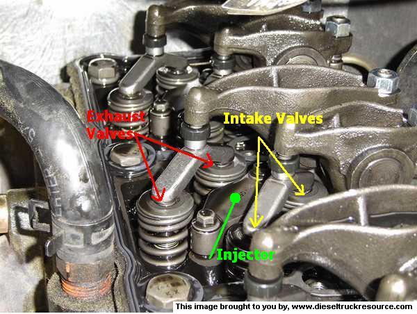
Valve layout.
This is the valve layout. The shorter rocker arm is always for the intake valves. The longer one is always for the exhaust valves. I highlighted the injector for reference.
4. Measuring valve lash.
Insert the feeler guage between the pivot stud and the Y bridge.

5. Setting the valve lash.

I am the one that wrote the article on the 24V valve adjustment, and I still have the pictures so I will post them here for everyone until the main article is fixed.
1. Fuel pump drive cover.
Disconnect the breather tube from the fitting. Then unscrew the plastic cap and this is what you will see:
2. TDC (top dead center) timing alignment.
Use a mirror and bar (hand crank) the engine to line up the notch with the line on the drive gear. The BDC (bottom dead center) notch is on the opposite side of the "hole" and is marked BDC on the timing cover.
Valve layout.
This is the valve layout. The shorter rocker arm is always for the intake valves. The longer one is always for the exhaust valves. I highlighted the injector for reference.
4. Measuring valve lash.
Insert the feeler guage between the pivot stud and the Y bridge.
5. Setting the valve lash.

Thread
Thread Starter
Forum
Replies
Last Post
NoSparkplugs
Suggestions, Comments and Site Questions
3
Dec 15, 2009 07:53 AM
cLAYH
24 Valve Engine and Drivetrain
7
Nov 14, 2007 08:03 PM