
Proper way to instal lock up toggle?

Registered User
Joined: Jan 2008
Posts: 166
Likes: 0
From: Wortham, Texas
take out the wire for the light on the fuse it may be messing with the grounding of the switch since it requires power to light but the trans lock up is a ground "loop" or at least that was my understanding we had the same problem with my brothers until we took out the light wire the only reason we got a lighted switch is because they didnt have a regular toggle
 I'll try unhooking the hot and see what happens. Thanks.
Registered User
Joined: May 2005
Posts: 1,623
Likes: 1
From: L.A. (Lower Arkansas)

Registered User
Joined: Jan 2004
Posts: 483
Likes: 0
From: Springfield, OH
Why not just use the diagram I posted earlier so you don't screw up your $4k trans? Also, use the jumper. The LEDs I installed are "line-of sight" so there's no way you can forget the L/U switch is activated. If you were to use the lighted toggle, I assume it would be mounted somewhere down on the knee bolster (plastic piece below the steering wheel) which will be easy to forget....unless you plan on keeping your eyes on the knee bolster and not the road.
Registered User
Joined: May 2005
Posts: 1,623
Likes: 1
From: L.A. (Lower Arkansas)
I like your set up, I just got to thinking about those leds and thought they might be too bright at night time and blind me. I mounted my switch exactly where you have your leds so it's very visable. I will try the jumper and if that don't work, I'll start over and go with your design, only problem is I'll have an extra big hole in my dash from the toggle switch. Maybe the 3rd time will be the charm. Thanks.
Maybe the 3rd time will be the charm. Thanks.
Registered User
Joined: May 2005
Posts: 1,623
Likes: 1
From: L.A. (Lower Arkansas)
I like your set up, I just got to thinking about those leds and thought they might be too bright at night time and blind me. I mounted my switch exactly where you have your leds so it's very visable. I will try the jumper and if that don't work, I'll start over and go with your design, only problem is I'll have an extra big hole in my dash from the toggle switch. Maybe the 3rd time will be the charm. Thanks.
Maybe the 3rd time will be the charm. Thanks.Registered User
Joined: Jan 2004
Posts: 483
Likes: 0
From: Springfield, OH
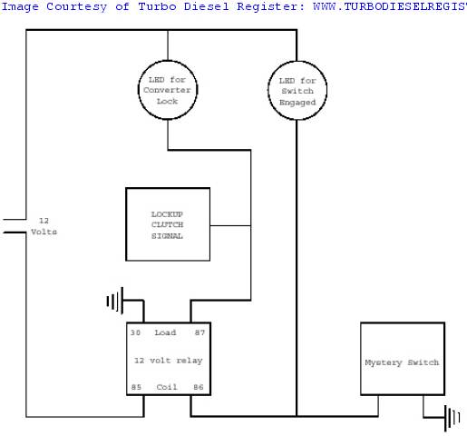
I have a diagram that MIGHT work with the LED toggle, I just can't upload from this computer. I'll try to explain. The 12v that goes to the LEDs in the diagram, simply take those LEDS out and run the 12v to the pin that accepts 12v on your toggle. The switched postion (someties refered to as accessory) of the toggle should go to pin# 86 on the relay. I'm not 100% sure it'll work but it may be worth a try. Again, use the jumper wire in the fuse box for the trans relay.
Registered User
Joined: Jan 2007
Posts: 1,820
Likes: 2
From: My head lays down in Murrieta, but the day light hours are spent in San Diego, Ca.
In order for a "lock up switch" to work properly, there should NOT be any 12v power in the system. The "lock up switch" just grounds the orange w/ black tracer wire so that the torque converter locks. In other words it's a grounding switch. The only time 12 v should be used is to provide power to a warning light. So when the "lock up switch" is activated (to ground the orange w/ black stripe wire), it will also ground the LED warning light turning it on. But the bottom line is that all the "lock up switch" uses is ground; Never 12 volt.
If I were you, I'd start by hooking just the switch up properly to ground, with out any lights. Use the 33 ohm resister and leave the transmission relay IN. After you've got all of that connected correctly and operating properly, then add an LED by connecting one side to 12v and the other to the output side of the grounding switch (the lock up switch). Of course, if you want the duel LED's you'd have to use a relay system.
If I were you, I'd start by hooking just the switch up properly to ground, with out any lights. Use the 33 ohm resister and leave the transmission relay IN. After you've got all of that connected correctly and operating properly, then add an LED by connecting one side to 12v and the other to the output side of the grounding switch (the lock up switch). Of course, if you want the duel LED's you'd have to use a relay system.
Registered User
Joined: May 2005
Posts: 1,623
Likes: 1
From: L.A. (Lower Arkansas)
In order for a "lock up switch" to work properly, there should NOT be any 12v power in the system. The "lock up switch" just grounds the orange w/ black tracer wire so that the torque converter locks. In other words it's a grounding switch. The only time 12 v should be used is to provide power to a warning light. So when the "lock up switch" is activated (to ground the orange w/ black stripe wire), it will also ground the LED warning light turning it on. But the bottom line is that all the "lock up switch" uses is ground; Never 12 volt.
If I were you, I'd start by hooking just the switch up properly to ground, with out any lights. Use the 33 ohm resister and leave the transmission relay IN. After you've got all of that connected correctly and operating properly, then add an LED by connecting one side to 12v and the other to the output side of the grounding switch (the lock up switch). Of course, if you want the duel LED's you'd have to use a relay system.
If I were you, I'd start by hooking just the switch up properly to ground, with out any lights. Use the 33 ohm resister and leave the transmission relay IN. After you've got all of that connected correctly and operating properly, then add an LED by connecting one side to 12v and the other to the output side of the grounding switch (the lock up switch). Of course, if you want the duel LED's you'd have to use a relay system.
Registered User
Joined: Apr 2008
Posts: 69
Likes: 1
From: Concord, Ca USA
Thanks for the tips about this lock up switch set up. 
I used J Double's schematic and wired mine up yesterday but have one nagging problem. I use 2 LEDs, green for normal lock up and red for manual. I have a problem with the green LED. When ever it's in the circuit I get a CEL and 4-6 codes. I can clear all the codes, start the engine and if touch the negative lead of the LED to the lock up solenoid wire the CEL comes on!
I've tested LED it's self and its ok. Other than than circuit is fine.
I wired it just as J Double's schematic using a floor mounted dimmer switch to ground the relay, except I added a 33ohm resistor at pin 30 of the relay and didn't take out the trans control relay under the hood.
Registered User
Joined: Jan 2004
Posts: 483
Likes: 0
From: Springfield, OH

Registered User
Joined: Jun 2025
Posts: 1
Likes: 0
Hello!
Yes I know, really old threat but hope to find some help here...
I have 1996 47re...
Goerend - Triple Disc Torque Converter
Fitted TransGo TFRE-PRO Reprogramming Kit.
I used 33 ohm resistor and toggle switch as here are desgribed. Relay is in. I also use diode so when I use manual lock switch then PCM don't see it.
When I flip the switch torque converter will lock but overdrive will engaged to.
Really weird is that when OD is switched off, shifter in D and second gear engaids and when I flip lock swicks transmission will lock the converter and sift to third gear...

Thread
Thread Starter
Forum
Replies
Last Post
CODODGE2500MAN
Performance and Accessories 2nd gen only
7
Nov 18, 2009 09:49 PM
Mostwanted
Performance and Accessories 2nd gen only
7
May 28, 2003 05:27 PM