When you click on links to various merchants on this site and make a purchase, this can result in this site earning a commission. Affiliate programs and affiliations include, but are not limited to, the eBay Partner Network.
I'm going to be embarking on this little adventure very soon. I'll be ordering parts once I finish drawing up my plan of attack (need a little help though) and will post a tutorial in this thread for how I'm going to approach this project.
First, here are the part numbers for the two most requested parts:
I've been studying relays a lot here lately in preparation to do this project and have seen quite a few different ways to wire the switch panel up to the relays as well as wiring the relays themselves, so there is a bit of confusion and would like some clarification.
I'm looking at getting one of following Bussman 5 micro relays/10 fuses, fuse blocks:
15303-2-2-4 - 2 internal buss bars: one for the relays, one for the fuses
15303-5-2-4 - fuse only internal buss bar
Since the switches are switched-ground, does it really matter if it goes on pin 86 or pin 85?
On the fuse block with two buss bars, the diagram for it shows pin 86 attached to the relay buss bar. If pins 86 and 30 or 86 and 87 have +12V connected to them (various threads had those two connected from one fuse), would it not be simpler to use the fuse block with 2 buss bars, eliminating the need to use a jumper? The relay buss bar could be connected to an ignition source, providing power to pin 86 only when key is on (the coils I may use only draw ~97.5 mA @ 12V), pin 85 attached to the switch bank (that would be the ground for the coil), use a jumper from pin 30 to a fuse which would be connected directly to the battery, and the load connected to pin 87.
Will that work what I mentioned above, or am I way off in my thinking? I'd like to think I finally got a grasp on how relays work, but just want to be sure.
Thanks all for the help!
BTW, the source of inspiration for how I may approach this project for a clean install gives a GREAT tutorial on the two bussman fuse blocks above along with a ton of useful parts, connectors, etc he used in his project: DIY Bussmann RTMR Fuse Block, Part 2 ? Parts | Bodenzord
The way I read it, your plan will work just fine. This is a bit long and I'm not sure about your technical understanding so bear with me and no offence if I explain in very simple terms.
Most automotive style relays are not polarity sensitive for the coil or contact terminals. If you use relays that have a built in diode across the relay coil, they are polarity sensitive and will be marked as such.
A diode is essentially a check valve for electricity, it only flows current in one direction. When a relay coil de-energizes the magnetic field collapses across all of the wound wire in the coil and can make a very large voltage spike, very similar to how a generator with a magnet passing by wound wire creates electricity. The diode is connected across the terminals so when power is applied to the coil, it will energize as normal and not allow a short circuit. When power is removed, the coil de-energizes and the voltage spike flows backwards which the diode allows to short circuit between the terminals instead of inside your switch. In the case of the aux switches you are using, there is no switch contact but actually a (somewhat) sensitive electronic circuit that uses a transistor to send the ground signal out to the relay.
I used regular non diode relays on my setup which uses a similar fuse block (Littlefuse HWB-60) and the same switches and have had no problems for quite some time. I don't expect the micro relays to cause enough of a voltage spike to damage the circuit inside the switch module.
As for the jumper or buss connection, it is perfectly fine to have the power to the contact (30) and power to the coil (85) shared so all you have to do is finish the circuit with the switched ground. I usually do relays this way for convenience of only having one fuse per circuit. The only downside from a technical perspective is that the relay coil and switch aren't protected if they are sharing lets say a 30 amp fuse with the load. If there is a short in your wiring on the control portion of the circuit you could wreck a switch or burn out the relay coil before the larger fuse for the actual accessory melts but honestly, the likelihood of components melting before a fuse would take at least a few dead shorts before you have issues. As long as you double check your work before turning it on and ask questions like this one instead of guessing, you will be fine.
After I posted, I did some more reading on relays and discovered what you mentioned about the diode type relays. The relays I'll be using has a resistor in parallel. Doesn't make sense to get the diode type relays for this project.
I do have a minor background in electronics and understand quite bit...just got hung up on relays for some reason and how they would tie into the aux switches. I forgot about the National Instruments Multisim that I used in a circuit theory class a few years ago, so I reinstalled it, did some testing to confirm my thoughts from the initial post, and came up with the attached schematics. Everything appears to work, but it will remain to be seen how it behaves with the actual switches.
It makes sense why you would want to jumper the two together for simplicity. However, I think it would be better to have power to the coils only with the key on, in case a wire from one of the switches somehow become damaged and touches a ground point on the vehicle. So, I'll definitely be keeping the contact and relay power separate.
With that said, here is a couple diagrams. I'd appreciate any feedback if something doesn't make sense or it won't work with the switch bank. The first diagram was just to demonstrate how it works. The second was cleaned up and relay pin numbers added.
Parts research still in progress, however, the auxiliary switch bank and harness are on order from FactoryMoparParts.com.
Last edited by 6.7L MegaCab; 02-28-2016 at 07:42 PM.
Reason: Edited for clarity, simplicity, and irrelevant information removed
I see no issues with your drawings other than the 20 amp fuse is way overkill for the relay coils. If you're worried about nuisance tripping that certainly won't be an issue, could probably get away with a 5 amp. Keep in mind you will need at least 5 wires into the cab for the mopar switches if you grab a ground from under the dash somewhere and 6 if you plan to run directly to the battery negative post. Even though they are not sending the 12 volts out, the circuit in the switch needs power and they have little orange indicator lights when they are on.
That's funny you mentioned that. While at work a couple days ago I drew up the schematic on excel to see what I may be missing, that's when I realized the 20A was way too much. With those relays only putting out about 97.5 mA, a 5A fuse is plenty...there really shouldn't be any nuisance tripping with a 5A fuse.
This is my plan so far:
10 AWG TXL wire for the accessories
18 AWG GXL wire for the switches using the following:
5 pin Weather Pack Connector #WPT-5 (12034342) for a short pigtail off of the RTMR
5 pin Weather Pack Connector #WPS-5 (12065158) for the switch harness into the cab, then use crimp/solder/seal butt connectors to connect to the 4 switch grounds on the switch bank wiring harness. The 5th wire will be capped off for future use.
The 12V and ground for the switch bank will be tapped into from the harness attached to the back of the RAM emblem.
So, 4 wires for the 4 switches and 1 spare into the cab. Is that what you were referring to for the 5 wires or am I missing something?
The switches finally shipped today; still making a parts list and finding suppliers to get everything from for the connectors and wires...should be ready to order the rest of parts by next week.
Attached is another revised diagram showing all 5 relays. I attempted to draw out the switch bank, separate spare switch and some connectors. Changed the relay fuse to 5A and added an inline 80A fuse (or breaker...haven't decided) for the accessories.
I went with a 6 pin weatherpack from my fuse block and took 12V and ground directly from the battery instead of using the oem harness behind the dash. If you plan on using that to power the switch bank you will only need 4 wires. On the other hand, a spare wire through the firewall isn't a bad idea even if it only ever gets used as a pull string to fish more in the future.
Also, if you're looking for an assortment of weatherpack stuff locally, try a Chevy dealer. They use them on **** near everything and had a ton of stock at the one here.
I think I'll be getting the 12V directly from the harness behind the dash. From the sounds of it, both connectors are the same, so I'll unpin the appropriate wires from the oem plug currently in place, and put them in the new plug...I'll know once I get ready to do this project...still deciding on wires.
Thanks for the tip for the checking out the Chevy Dealer. I may give them a call to see what their prices are if they have them in stock.
Well, I got the part in 2 days after ordering...all the way from Florida to Vegas...with first class shipping at that
I couldn't resist the urge to open up the switch bank to see what was really going on on the inside of it. I'll do my best explaining what is what in each picture.
But, before I begin:
I am really curious how the switch bank that comes in the Laramie models operates. If those switches are switched to ground, then that means those switches could be used as auxiliary switches instead...especially if you want 6 fully functional switches to power your devices. Otherwise, someone could probably fabricate a push on/push off type switch and a light spring to set inside of the blanks next to aux 2 and 3, cut off the tabs, similar to aux 1-4, so they can be pressed. The center blank is not meant to be pressed, but could house a toggle or micro rocker flush mount switch.
Here are the pics...if anyone would like a different view or better images, let me know. I think it will still be another couple weeks as I am debating on running wires to potentially use the blanks for switches...even for future use. Since I'll definitely be running at least 5 wires for the 5 relays (one spare), I may put a switch in the center while it is out.
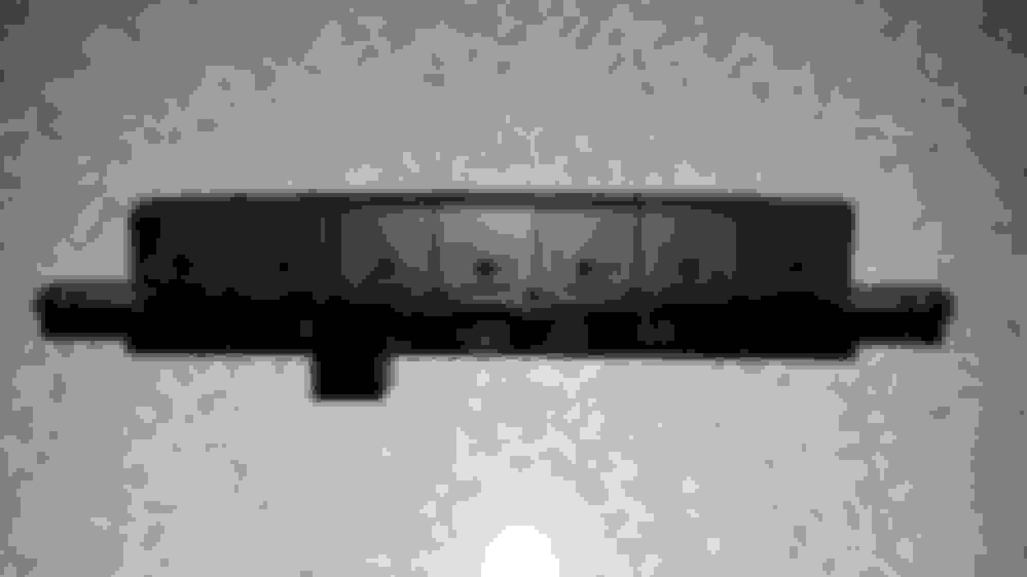
Bottom look of the switches. If you look close enough, there are tabs present on the two switches on both sides of center as well as the same slots found on the 4 aux switches. My assumption is that someone could fabricate some type of push on/push off switch to put on the inside with a light spring to use one of the blanks.
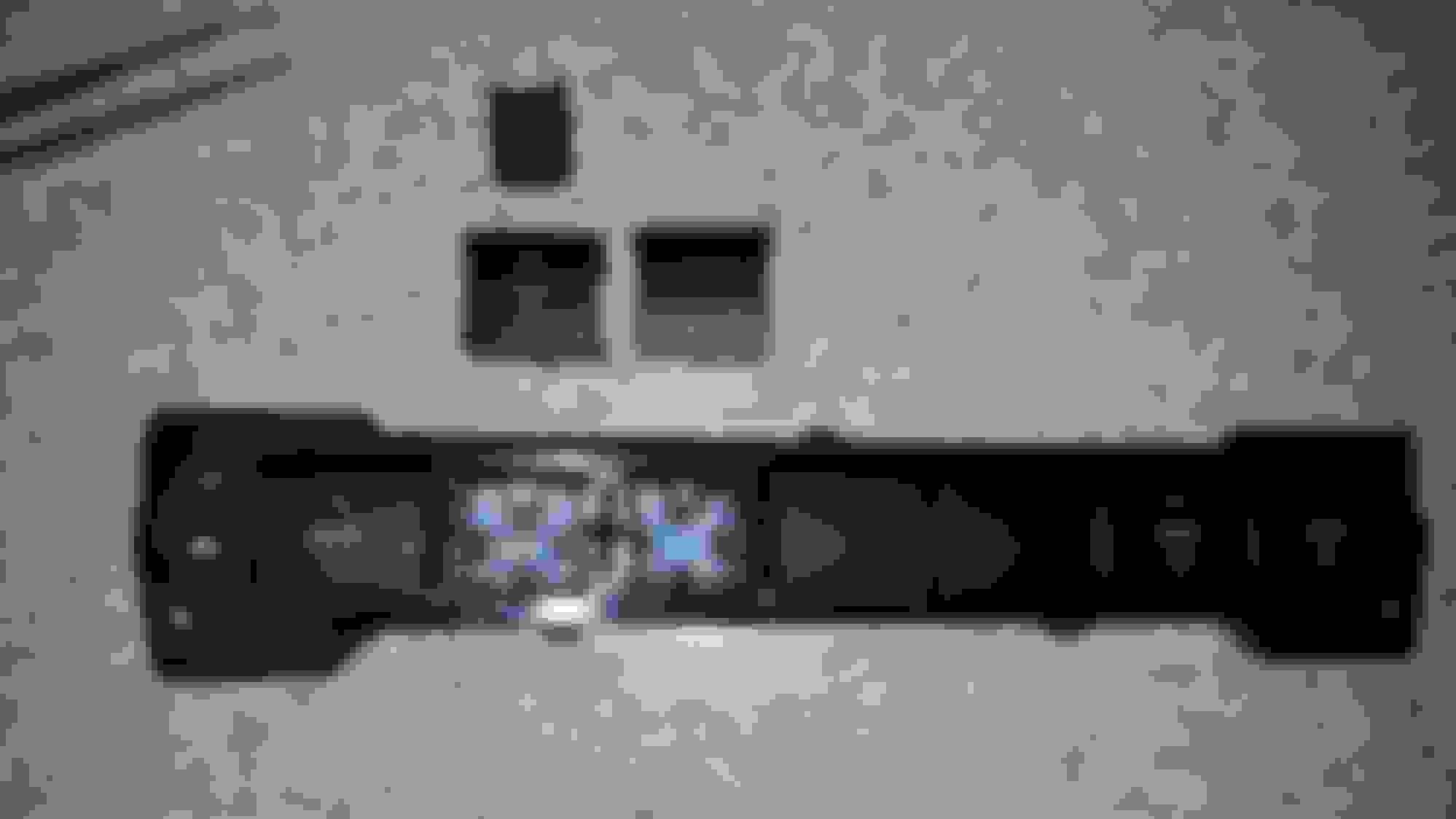
Front view #1 of the switch bank with aux 2 and blank removed. There is some resemblance. I am curious as to what the switch bank on the Laramie looks like and how it is controlled.
Front view #2 of the switch bank with aux 2 and blank removed. This one also as another insert removed that makes contact with the rubber pad, that when pressed, makes contact with circuit board and acts as a spring as well.
inside view of aux 2 and blank. The aux 2 appears to have an insert with the led lens that directs the led light on the circuit board.
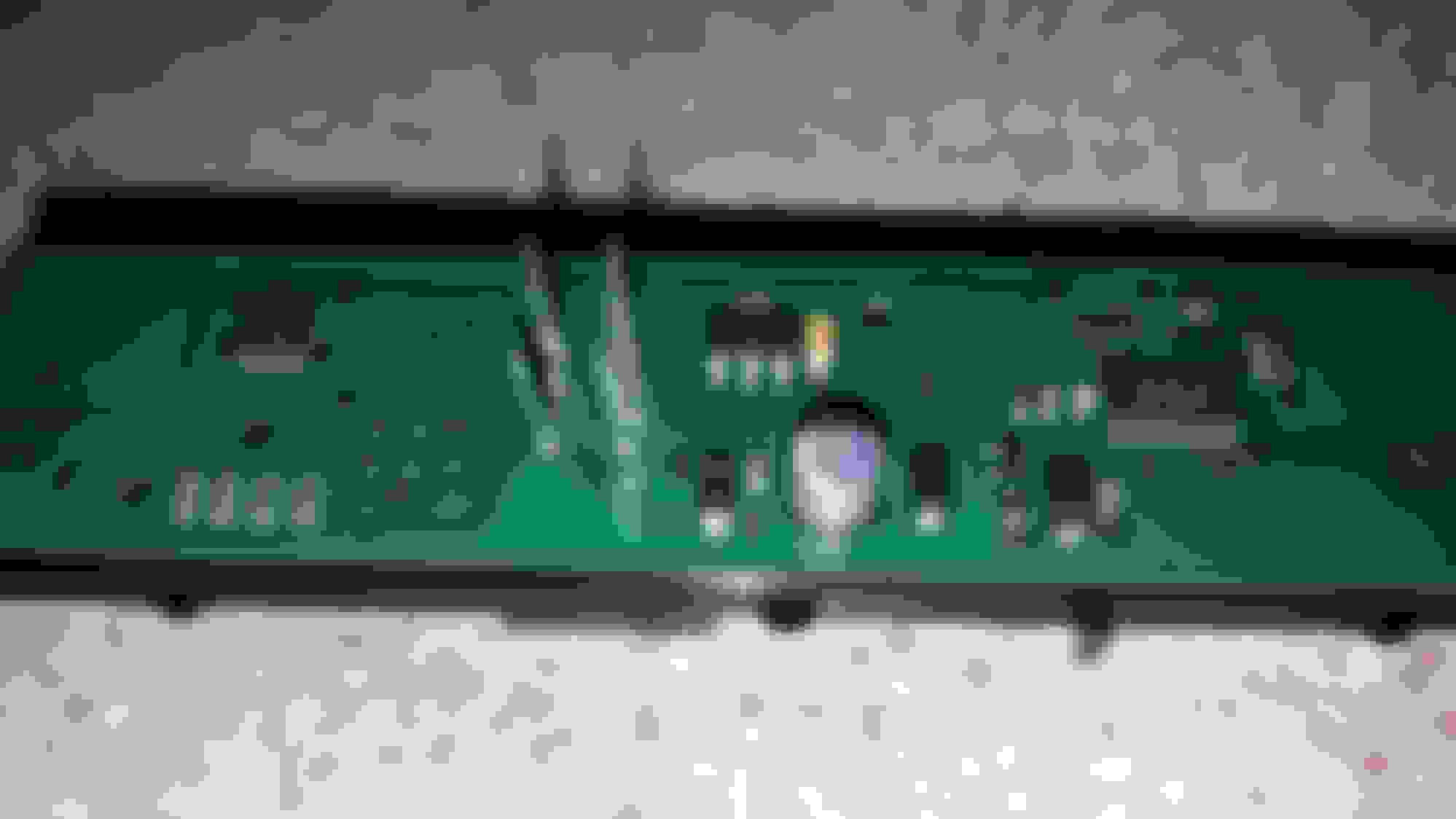
This view is of the circuit board that would face out towards the switches. The gray mat above it, attaches to the board, then is set into the housing.
The is the bottom or back view of the circuit board where all the electronics are at.
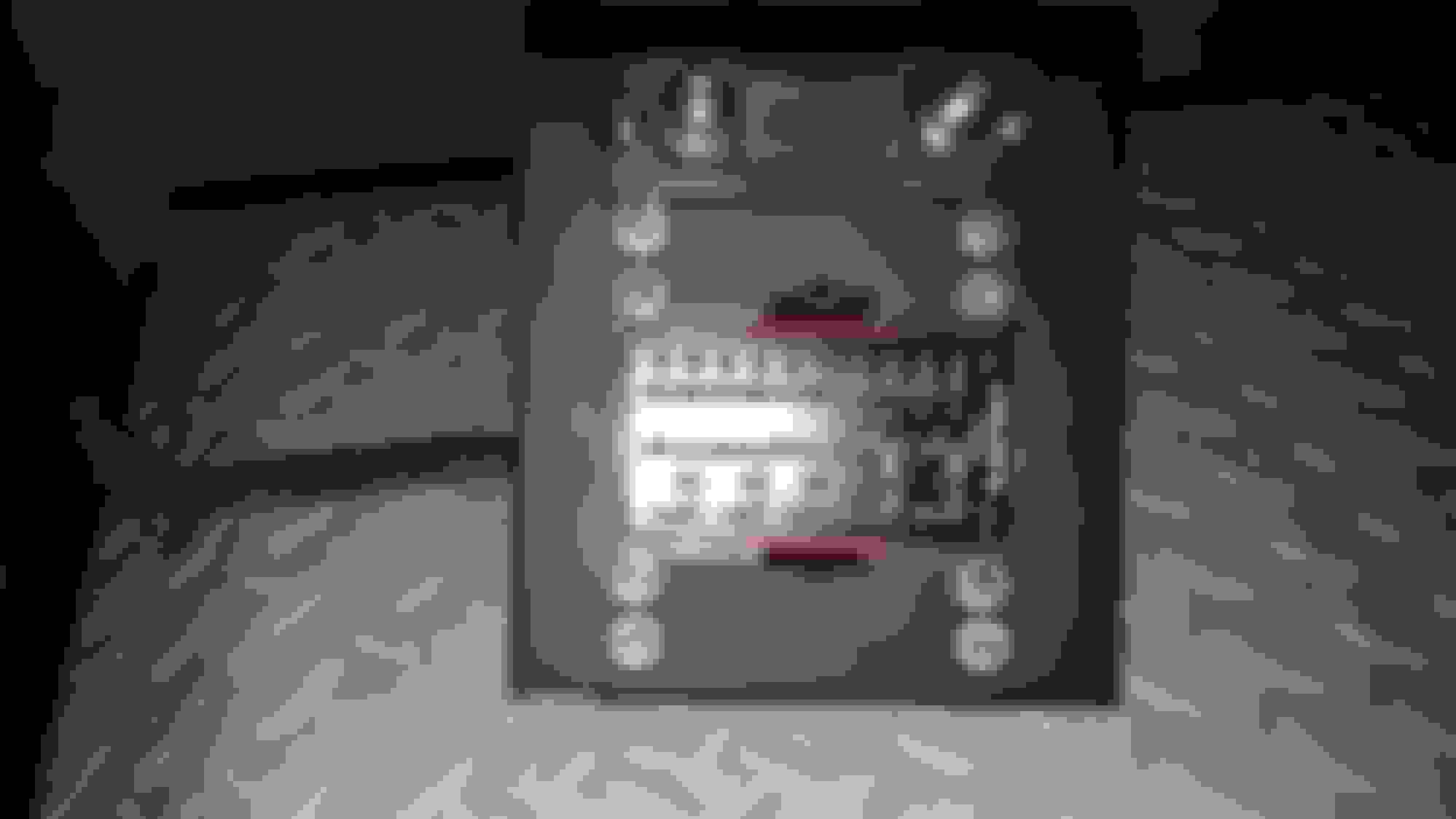
Another pic to get a little better focus on the letters/numbers of the components.
Again, another pic of the back of the board to see the numbers a bit better. The chip slightly right of center is a PIC16F506-I/SL, which is basically the brains of the switch bank. The chip with 3 contact pins next to the male pins that the harness hooks up to, is a TLE 4264-2 5V Low Drop Fixed Voltage Regulator that can accept input voltages of 5.5V to 45V.
Just wanted to provide a bit of an update. Been very busy the last few weeks, so not much progress. Wanting to do this right and make this whole setup look somewhat professional is a lot more work than I thought it was going to be. I finally have a parts list of "most" of the items I'll be using - which was the hard part. Now, vendor search is under way.
I do have the wires on hand now. Once I order everything, I'll post the parts list and vendors that I used.
Also, in reference to my last post about the Laramie switch bank. It won't work like I thought as it is a completely different circuit that uses the LIN Bus to activate the appropriate accessories, thus the reason it uses less wires: LIN, GND, +12V.
Sorry it's taken so long to post. I've been making slow, but steady progress on this little build and am nearly complete. This post will be for the parts that I used, broken down by section, so the quantities will be split where same part number is used in multiple areas.
Wire
Wirebarn.com: 18GXL6X25F, 6 Pack 18 Gage GXL Wire - SIX (6) Colors, 25 Foot Each Color (Black, Blue, Brown, Green, Yellow, Red)
EFIConnection.com:
101-00174, 10 AWG TXL BLACK Wire (10 feet)
101-00138, 10 AWG TXL RED Wire (10 feet)
Mouser.com:
Qty - Part #, Description (Where used in the build)
1 - 504-15303-2-2-4, Power Conditioning POWER DISTRIBUTION MODULE Bussmann RTMR 5 Relay, 10 Fuse
10 - 829-12010300, CABLE CAVITY PLUG GREEN (down center relay holes on backside of RTMR)
------------------------------------------------------------------- RTMR to Weather-Pack 6-way Female Connector Switch Harness
-------------------------------------------------------------------
1 - 829-12015799, 6P FM BLK CON ASSY 20 AMPS (connector on pigtail permanently attached to RTMR)
6 - 829-12089188, FEMALE TIN PLATED CBL RANG .80-.50MM2 (20-18 AWG terminals for Weather-Pack female connecter)
5 - 829-12110847, FMALE 280 SERIES TIN CBL RANG 2.64-1.96MM (18-16 AWG terminals for RTMR)
11 - 829-15324982, INDV. LOOSE CBL SEAL GREEN (Metri-Pack 280 20-18 AWG seals; 5 seals for RTMR, 6 for female connector)
Wires (not from Mouser): ~13 inches 18 AWG GXL - Black, Blue, Brown, Green, Yellow, Red
=====================================
------------------------------------------------------------------- Weather-Pack 6-way Male Connector to Aux Switch Bank Harness
-------------------------------------------------------------------
1 - 829-12010975, 6P MALE BLK 20 AMP WEATHER PACK SHROUD
6 - 829-12089040, MALE TIN PLATED CBL RANG .80-.50MM2
6 - 829-15324982, INDV. LOOSE CBL SEAL GREEN (Metri-Pack 280 20-18 AWG seals; for male connector)
Wires same as above: length depends on where you mount box under hood to run to Aux Panel
=====================================
------------------------------------------------------------------- Jumper Wires, from fuse (odd number fuses) to relay pin 87 on RTMR
-------------------------------------------------------------------
10 - 829-12110853, FMALE 280 SERIES TIN CBL RANG 4.20-3.00MM
10 - 829-15324981, INDV. LOOSE CBL SEAL BLUE (Metri-Pack 280, 12 AWG seals - they don't have ones for 10 AWG, however TXL wires have a thinner wall)
Wire: Red 10 AWG TXL, 5 pieces, 3.5 inches long
=====================================
------------------------------------------------------------------- Accessory Cables - RTMR side
-------------------------------------------------------------------
10 - 829-15300027, 2P FM BLK CON ASSY 280 SERIES 30 AMPS
------------------------------------------------------------------- Male Connectors Used on Accessories
-------------------------------------------------------------------
10 - 829-15300002, 2P MALE BLACK 280 SERIES 30 AMPS
10 - 829-15300014-B, TPA M/P 280 LK (these are to hold the pins or plugs in place)
20 - 829-12010300, CABLE CAVITY PLUG GREEN (If you already have accessories lined up, you only need enough to plug the unused connectors, 2 per plug)
The following are the Mouser.com part numbers and sizes for the pins and cable seals that are necessary based on the wire size used in your accessories. Keep in mind the distance from the power distribution box to your accessory as you don't won't to under-size the wire. For example, if your accessory calls for 20 Amps, but the distance of wire is 25 feet (12.5 feet of +12V and 12.5 of ground), you may want to use a 10 AWG wire. Check out the following PDF if you need help determining wire size: Wire Selection Chart
Terminals:
829-12129497, MALE 280 SERIES TIN CBL RANG 3.80-2.45MM (16-12 AWG)
829-12048159, MALE 280 SERIES TIN CBL RANG 0.5-0.8MM (20-18 AWG)
829-12124977, MALE 280 SERIES TIN CBL RNG 2.20-1.30MM (22-20 AWG)
Cable Seals:
829-15324981, INDV. LOOSE CBL SEAL BLUE (12 AWG wire only)
829-15324980, INDV. LOOSE CBL SEAL GRAY (16-14 AWG wire)
829-15324984, INDVL CABLE SEALS TAN (20-18 AWG)
Other sizes can be found at Whiteproducts.com
=====================================
The next posts will be some of the special tools used, followed by some pictures of the build.
The terminal pins for the Weather-Pack and Metri-Pack, as well as the RTMR required a special tool to crimp them to the wires and also crimp the wire seals in place. You can opt to use the fancy $100+ all-in-one tool or the cheaper alternatives. The specific tools I used are as follows:
T-18 GM Delphi Weatherpack Crimper Tool - this is used to crimp the terminals to the wires as well as crimp the seals.
T-18 Crimper
T-11 Delphi Packard Five-cavity Wide-range Crimping Tool 22-12 AWG / 24-14 AWG - this particular one is needed to crimp the terminals to the 10 AWG wire. The T-18 is used to crimp the seals.
T-11 Crimper
Some of the other necessary tools are wire strippers and maybe a utility knife for the 10 gauge wire if you don't have a wire stripper...just be careful not to cut into the copper strands.
Lastly, a soldering iron if you want to solder the terminals after they are crimped in place. This is something that I did for the extra piece of mind.
Because the guy at the above website built his setup for his Tacoma, you won't need to do everything he did for the switch harness that plugs into the RTMR harness and connects to the switch bank. You only need 6 wires, not the 9 wires. Everything else, for the most part was similar to the way he setup his unit.
Since I slightly messed on my wiring (wires out of order), I recommend installing the wires in alphabetical order for relays 1 - 5.
Black - Relay 1 to Aux 1
Blue - Relay 2 to Aux 2
Brown - Relay 3 to Aux 3
Green - Relay 4 to Aux 5
Yellow - Relay 5 to your 5th switch
Red - second power source for the aux switch bank (I forgot this setup was for ground switched, so after all was said and done, the black wire was used for that instead of the red wire).
Part 1: RTMR Switch Harness Pigtail
The pigtail hooked up to the RTMR. Yes, that is F4 tape wrapped around the wires.
Part 2: This is the parts for the switch harness that goes through the firewall
The RTMR jumper wires
Jumper wires completed along with soldered terminals
Custom bracket. Since I wanted all grounds terminating at the RTMR, there isn't enough room next to the drivers side battery where the factory relay box would have been located. So, after some analysis, I decided to make the bracket so that it sides inside of the box the TIPM is housed in, between the TIPM and battery. The tab in the photo is to keep the bracket from sliding left to right, so it keeps it snug in the box close to the fender. The bracket is made from an unused shelf out of one of metal shop cabinets, similar to what Harbor Freight carries. Using a nifty metal ruler, pencil, permanent marker, and a dremel, the cuts turned out pretty good.
RTMR, ground bussbars, and ANL fuse holder that will house an 80 amp fuse.
bottom side showing the ground bars. If you look closely, you'll see a black wire terminating on the internal bussbar for the relays. A 5 AMP fuse will hook up either directly to the battery or piggyback on a fuse in the TIPM to provide power to the coils through the internal buss while also sending power down that black wire for the secondary power source for the switch bank.
accessory pigtails wrapped in Scotch 23 splicing tape and tied off with wax string us avionics guys used on military aircraft.
The accessory pigtails for the 5 relays are installed. I still need to install the locks so the green plugs won't fall out. The 5 fuse only accessory pigtails will be installed before this is installed on the truck
One thing I forgot to mention in the previous post is to connect both of the ground bussbars together, then run a ground wire to the negative terminal on the battery...or another location on the truck. I may run directly to the battery.
Here is the aux switch bank showing where I drilled holes for the rocker switch installed in the center blank. Do note, this is on the bottom side with switch bank facing you.
Top view of the RTMR sitting in place. Not final yet, but wanted to show where it's being installed. Use 4 gauge wire to connect from the fuse holder to the battery and from the other side of the fuse holder to the RTMR fuse side buss on the bottom.
side/bottom view
This is just to show how the tab was utilized. If I ever remove the TIPM, I'll install a bolt or two to the box the TIPM sits in to secure the RTMR in place.
I think this pretty much completes it. If there is any confusion on what I did, please let me know and I'll clarify or provide better pictures.
If you are going to follow the tutorials on bodenzord.com, take a note about how he is using his relays. He installed them upside down in the RTMR (with sound reasoning), but in my testing it didn't matter which way they were installed as pins 85 & 86 are to energize the coil, regardless which one has a ground or +12V connected to it. Since our setup is switched ground, the relay bussbar is going to have power from the battery, so it didn't matter.
Since the RTMR is rated for 80 Amps, be sure to use an 80A fuse or circuit breaker.
 02-25-2016, 12:02 AM