Beefing-Up My A518 Transmission (Updated As It Occurs)
 07-25-2010, 12:40 AM
#46
1st Generation Admin
Thread Starter
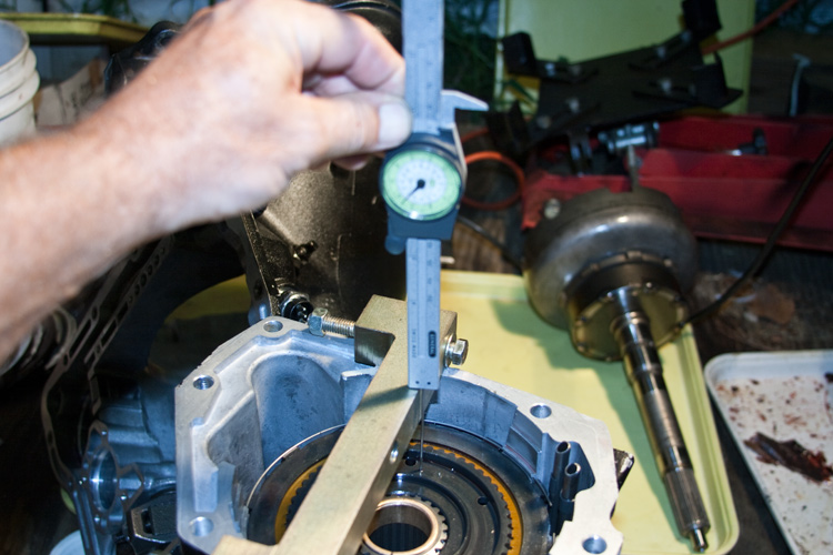
Finally, I can install the oil pump / input shaft support assembly and check the end-play.
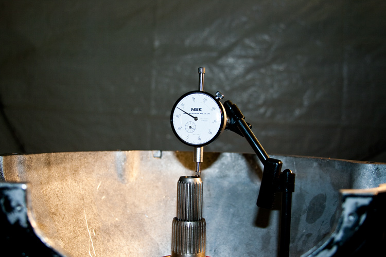
Too tight. I'm gonna have to install a thinner thrust washer either between the input and intermediate shaft and/or the front clutch's thrust washer. Either way, a parts run is in order.
I'm still dinking with the valve-body. Perhaps I can finish it tomorrow (Sunday).
Too tight. I'm gonna have to install a thinner thrust washer either between the input and intermediate shaft and/or the front clutch's thrust washer. Either way, a parts run is in order.
I'm still dinking with the valve-body. Perhaps I can finish it tomorrow (Sunday).
Last edited by BC847; 07-28-2010 at 10:07 PM. Reason: Changed from too loose, to too tight.

 Makes me glad I printed off the first build thread and had my tranny guy copy it on my 518
07-25-2010, 04:05 PM
Makes me glad I printed off the first build thread and had my tranny guy copy it on my 518
07-25-2010, 04:05 PM
#48
Guest
Posts: n/a
For the novices, don't install the o ring on the OD of the pump while checking input end play, then you can pull the pump back out without the slide hammer. Do use the new gasket that goes between the pump and the case, this effects end play. Just don't forget to install oring after getting endplay right.
07-28-2010, 10:32 PM
#50
1st Generation Admin
Thread Starter
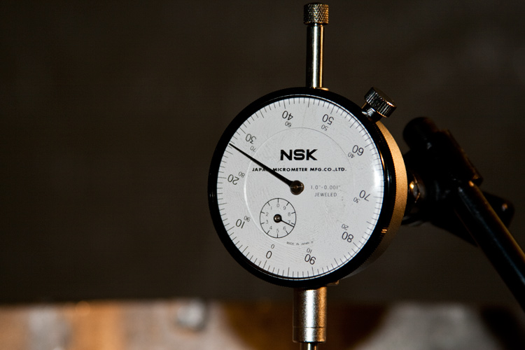
In the last image above, the micrometer shows 0.027(.5)" total end-play (I had originally posted that was too loose). That is in fact too tight. The FSM wants 0.034 ~ 0.084". I would need to loosen it up by 6.5 thousandths to meet the minimum required.
I've got the full set (including those currently in use) of both the selectable thrust washers that go between the intermediate clutch drum and the input shaft support, and those that go between the input and intermediate shaft.
Between the two sets of selectable thrust washers, I was able to swap things around enough to arrive at 0.040" total end-play. (On the snug side of the acceptable range).
Unfortunately, that throws my adjustments of the bombed forward clutch-pack out the window.
Frankly, I'm done with it. I'm having a fit trying to get the 5-disc clutch-pack to ride the associated internal hub correctly (that being the splines on the external diameter of the front planetary's annulus gear). Correctly being that whether applied, or released, all the disc's splines must remain fully engaged with that internal hub.
I've been told now by at least two big-gun diesel transmission builders that they are putting well over a thousand ft/lbs through the four disc setup with no problems. My dinky little self don't need no 5-disc forward clutch. I was informed that when I burn the 4-disc deal, THEN worry with the 5-disc deal.
So be it. Crap! I don't know what I'm gonna do with it right now.
I reckon I'll reconfigure that clutch-pack tomorrow night and then finally button-up the main case. I've still got to take care of an issue with the valve-body. I'd like to think I can have it all together by this weekend (I said that last week") ).
).
SunCoast should receive the torque converter Thursday. They're gonna clean it up and take an additional 0.010" off here or there, while they are inside the thing.
Still hot outside.
I've got the full set (including those currently in use) of both the selectable thrust washers that go between the intermediate clutch drum and the input shaft support, and those that go between the input and intermediate shaft.
Between the two sets of selectable thrust washers, I was able to swap things around enough to arrive at 0.040" total end-play. (On the snug side of the acceptable range).
Unfortunately, that throws my adjustments of the bombed forward clutch-pack out the window.
Frankly, I'm done with it. I'm having a fit trying to get the 5-disc clutch-pack to ride the associated internal hub correctly (that being the splines on the external diameter of the front planetary's annulus gear). Correctly being that whether applied, or released, all the disc's splines must remain fully engaged with that internal hub.
I've been told now by at least two big-gun diesel transmission builders that they are putting well over a thousand ft/lbs through the four disc setup with no problems. My dinky little self don't need no 5-disc forward clutch. I was informed that when I burn the 4-disc deal, THEN worry with the 5-disc deal.
So be it. Crap! I don't know what I'm gonna do with it right now.
I reckon I'll reconfigure that clutch-pack tomorrow night and then finally button-up the main case. I've still got to take care of an issue with the valve-body. I'd like to think I can have it all together by this weekend (I said that last week
). SunCoast should receive the torque converter Thursday. They're gonna clean it up and take an additional 0.010" off here or there, while they are inside the thing.
Still hot outside.
07-29-2010, 12:33 AM
#51
Registered User
I can't imagine how finicky it must be to tear into one of these transmissions, I thought I had patience doing the body work on my truck. I look at all the pictures of the guts of that 518 and I quiver...
Hope all the time and effort turns out for yea David!
Hope all the time and effort turns out for yea David!
07-29-2010, 07:05 AM
#53
1st Generation Admin
Thread Starter
 08-01-2010, 07:12 PM
#54
1st Generation Admin
Thread Starter
Well, shoot .. .. .
I finally got to completing the valve-body. With discovering that crack in the shifter mount of the current upper section, I had to revert to my original. The stick in the mud was that I had drilled a couple of holes in it as part of an earlier shift-kit thing. With my current VB tuning, I didn't need those holes so I had to figure out how to plug them. Getting that out of the way allowed my to reassemble the valve-body for installation.
Just for grins and giggles . . . Let's say you're having an "Extra Special" day and dumped all the ***** out of the upper valve-body. DOH!
Here's where they go . . .
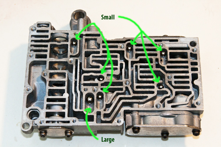
There's also a couple in the transfer-plate . . .
NOTE: You may have a ball or two less than that shown above pending your Shift-Kit and application.
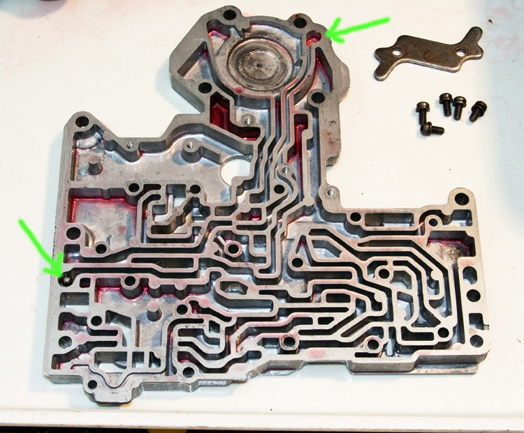
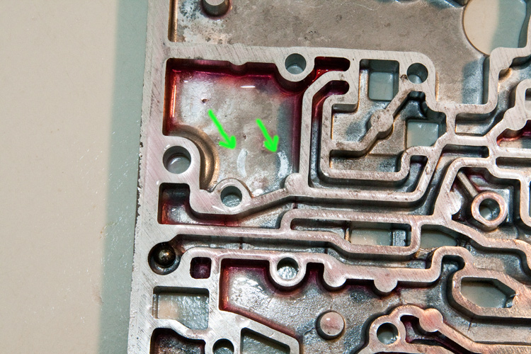
Speaking of that transfer-plate, as part of a general trans overhaul, there's a little transmission fluid filter that is located in the separator-plate. If not properly installed, that filter can wiggle around and potentially be damaged with wear. See the C-shaped skid marks? . . .
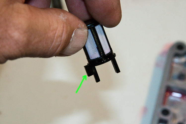
To prevent this, notice the tang on one side of the filter . . .
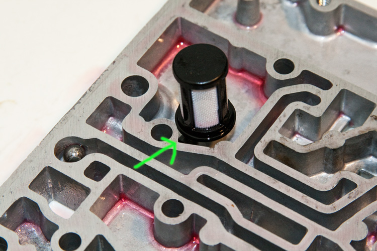
When installed correctly, that tang will be located as shown . ..
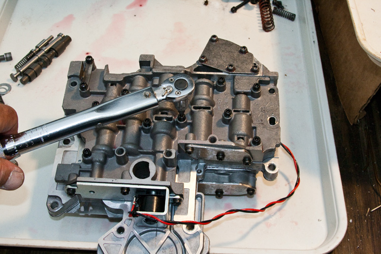
All the Allen-head screws are torqued to 35 in/lbs.
OK, fine. So prior to mounting the valve-body, using compressed air, I tested each of the clutch-packs and servos for proper operation. Everything works as it should . . . except for the forward clutch. It's engaging with a loud thud.
At the end of the day, that forward clutch pressure-plate that I machined, is designed such that it acts as a fulcrum for the forward clutch disc spring.
- The outer edge of that spring rides against a groove in the forward drum. When the clutch piston is applied, it moves forward the inner diameter of the spring. With the outer diameter of the spring in a fixed location, the spring acts as a lever. The pressure-plate acts as a fulcrum for said lever with the result being substantially increased apply pressure to the clutch-pack.
Yeah, well, . . . my machining that pressure-plate obviously altered the location of the fulcrum of the assembly. The end result is that with applying the piston, the whole spring has to move forward a little to compensate for that metal machined off (the wave snap-ring is compressed with said action). In doing so, the outer diameter of the clutch-spring is no longer fixed in it's proper place. With that, the clutch piston now makes a substantially longer stroke and is in fact, inverting the spring (it's a bowl shaped spring by the way). That's the loud thump I'm hearing. This won't do. >Sigh<
I had a spare OEM pressure-plate and went ahead and installed that. I tried every approach to moving that clutch-pack around that I could think of. From one angle of moving the clutch-pack itself (short of further machine work), to another of moving the inner hub to better suit the clutch-discs (shims behind that planet's thrust-washer). No love.
I went ahead and rebuilt the forward clutch-pack to factory/OEM specs with four clutches and steels. If I want to pursue increasing the clutch-steel count on my forward clutch, I'm gonna have to find an annulus gear for the front planetary gear-set that has longer splines for the forward clutch.
Now testing all the clutches and servos with compressed air again has them all work correctly. So I installed the valve-body and buttoned it up with a new fluid filter.
It's sitting out back with a fresh coat of satin black paint drying.
I'm hoping to have the converter back from SunCoast by this week's end.
In the mean time, I've got to make a mount for the exhaust down-pipe so as to attach it proper to one of the transmission, bell-housing bolts. That and rebuild the transfer-case.
I finally got to completing the valve-body. With discovering that crack in the shifter mount of the current upper section, I had to revert to my original. The stick in the mud was that I had drilled a couple of holes in it as part of an earlier shift-kit thing. With my current VB tuning, I didn't need those holes so I had to figure out how to plug them. Getting that out of the way allowed my to reassemble the valve-body for installation.
Just for grins and giggles . . . Let's say you're having an "Extra Special" day and dumped all the ***** out of the upper valve-body. DOH!
Here's where they go . . .
There's also a couple in the transfer-plate . . .
NOTE: You may have a ball or two less than that shown above pending your Shift-Kit and application.
Speaking of that transfer-plate, as part of a general trans overhaul, there's a little transmission fluid filter that is located in the separator-plate. If not properly installed, that filter can wiggle around and potentially be damaged with wear. See the C-shaped skid marks? . . .
To prevent this, notice the tang on one side of the filter . . .
When installed correctly, that tang will be located as shown . ..
All the Allen-head screws are torqued to 35 in/lbs.
OK, fine. So prior to mounting the valve-body, using compressed air, I tested each of the clutch-packs and servos for proper operation. Everything works as it should . . . except for the forward clutch. It's engaging with a loud thud.
At the end of the day, that forward clutch pressure-plate that I machined, is designed such that it acts as a fulcrum for the forward clutch disc spring.
- The outer edge of that spring rides against a groove in the forward drum. When the clutch piston is applied, it moves forward the inner diameter of the spring. With the outer diameter of the spring in a fixed location, the spring acts as a lever. The pressure-plate acts as a fulcrum for said lever with the result being substantially increased apply pressure to the clutch-pack.
Yeah, well, . . . my machining that pressure-plate obviously altered the location of the fulcrum of the assembly. The end result is that with applying the piston, the whole spring has to move forward a little to compensate for that metal machined off (the wave snap-ring is compressed with said action). In doing so, the outer diameter of the clutch-spring is no longer fixed in it's proper place. With that, the clutch piston now makes a substantially longer stroke and is in fact, inverting the spring (it's a bowl shaped spring by the way). That's the loud thump I'm hearing. This won't do. >Sigh<
I had a spare OEM pressure-plate and went ahead and installed that. I tried every approach to moving that clutch-pack around that I could think of. From one angle of moving the clutch-pack itself (short of further machine work), to another of moving the inner hub to better suit the clutch-discs (shims behind that planet's thrust-washer). No love.
I went ahead and rebuilt the forward clutch-pack to factory/OEM specs with four clutches and steels. If I want to pursue increasing the clutch-steel count on my forward clutch, I'm gonna have to find an annulus gear for the front planetary gear-set that has longer splines for the forward clutch.
Now testing all the clutches and servos with compressed air again has them all work correctly. So I installed the valve-body and buttoned it up with a new fluid filter.
It's sitting out back with a fresh coat of satin black paint drying.
I'm hoping to have the converter back from SunCoast by this week's end.
In the mean time, I've got to make a mount for the exhaust down-pipe so as to attach it proper to one of the transmission, bell-housing bolts. That and rebuild the transfer-case.
08-01-2010, 08:41 PM
#55
Registered User
Join Date: Oct 2009
Location: Claymont, Del and Horsham, PA
Posts: 1,830
Likes: 0
Received 1 Like
on
1 Post
Sounds like you had a lot of fun. I should probably inspect my trans before stuffing it into my heap, i would hate to have to do that twice...
This has been very informational and helpful and has me re-thinking my ability to do this, you haven't lost me yet on terminology or functionality of this trans. how about special tools?
This has been very informational and helpful and has me re-thinking my ability to do this, you haven't lost me yet on terminology or functionality of this trans. how about special tools?
08-01-2010, 09:13 PM
#56
1st Generation Admin
Thread Starter
With the exception of the summer heat beating the snot out of me, the trans upgrading is fun (to me). The challenge of doing something that wasn't meant to be. Certainly all the help I've gotten from everyone has made it easier. But still, taking the micrometer and having things fall where the FSM expects to see them is cool. I think the biggest thrill for me is coming to a better understanding as to how things work by laying hands on it.
As far as special tools go, . .
The tools for the overdrive sections no doubt.
- The cage to compress the big spring be it that which works with your shop press .. . .
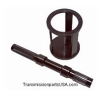
Or that which works on it's own . . .
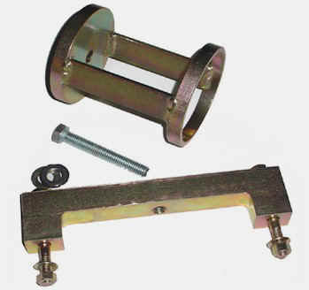
That first image shows a tool that mimics the intermediate shaft and allows one to align the OD clutch splines and planetary gear-set. I just used the intermediate shaft itself for that job.
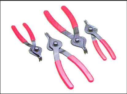
Otherwise, the typical Snap-Ring pliers . . .
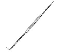
An assortment of picks . .
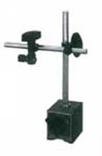
A magnetic mount for the micrometer used in checking final end-play . . .
As well as a caliper type micrometer that includes a means of measuring depth . . .
I used the common back-yard mechanic tools to fill in for many of the so-called special tools. Big C-clamps and sockets for removing the servo C-clips for example. Let your imagination fly!
As far as special tools go, . .
The tools for the overdrive sections no doubt.
- The cage to compress the big spring be it that which works with your shop press .. . .
Or that which works on it's own . . .
That first image shows a tool that mimics the intermediate shaft and allows one to align the OD clutch splines and planetary gear-set. I just used the intermediate shaft itself for that job.
Otherwise, the typical Snap-Ring pliers . . .
An assortment of picks . .
A magnetic mount for the micrometer used in checking final end-play . . .
As well as a caliper type micrometer that includes a means of measuring depth . . .
I used the common back-yard mechanic tools to fill in for many of the so-called special tools. Big C-clamps and sockets for removing the servo C-clips for example. Let your imagination fly!
08-02-2010, 10:44 PM
#58
1st Generation Admin
Thread Starter
SunCoast is gonna be able to tighten the converter a little. It's gonna cost a new billet stator though. Should have it back by Monday at the latest.
Got the transfer case in a number of pieces.
Should have it back by Monday at the latest.Got the transfer case in a number of pieces.
08-03-2010, 11:39 AM
#59
Guest
Posts: n/a
I'm guessing by what I get from your posts that you cut down the pressure plate in the rear clutch on the side that touches the bellville washer? To quote dire straits "oh, that ain't workin". If you have access to a surface grinder you can take half of what you need off the top (the flat side) of the pressure plate. The other half gets taken off the top of the reaction plate (that's what I call the top thick plate in the clutches, don't know the offishul name) by lathe or grinder.
08-03-2010, 11:45 AM
#60
Guest
Posts: n/a
If you do any junkyard scrounging, two things to watch for, some early mid 70s slant six 904s have 4.2 kickdown levers. same era and back 727s had a steel spacer ring that goes next to the bellvelle spring in the rear clutch instead of the later plastic one.