T-Cows Hydroboost thread....
 11-08-2015, 11:12 PM
#1
Registered User
Thread Starter
T-Cows Hydroboost thread....
OK I am going to do a write up on my Hydroboost adventure. See I made some mistakes, and learned a few things I had not come across during my internet searching and research.
This was my first mistake.
If you plan on pulling the push rod for a rebuild, take the time to build yourself a proper puller! You should NOT pull on just the push rod and expect it to POP out.
This is what can, and probably will happen.
Redneck engineering gone bad....
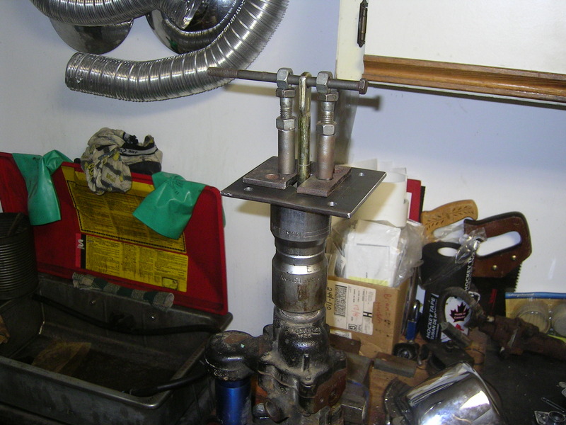
And the results of the above engineering disaster....
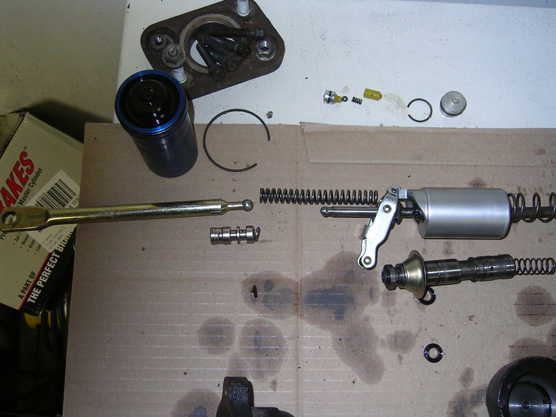
See the push rod is supposed to pop out of that collar, and leave that big long spring still attached to the push rod on the piston. Doooh!
This is the removal tool I made up, Thanks to Mark (MKnittle) for the idea!
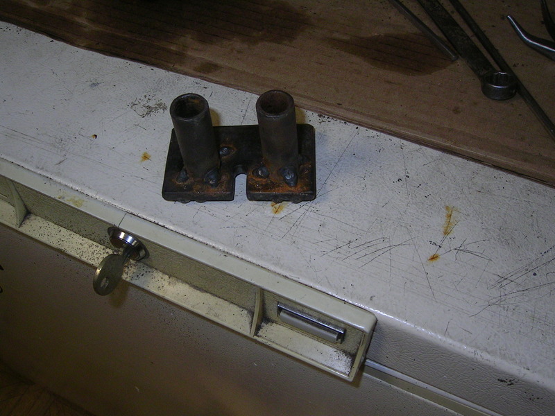
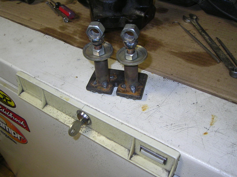
This allows the push rod to be popped out without any detriment to the rest of the system.
 11-08-2015, 11:26 PM
#2
Registered User
Thread Starter
Second mistake I made was assuming that all Hydroboost units are the same. After I damaged the dodge unit I went to the wreckers and grabbed a complete unit from a 95 Astro Van, thinking I could just combine the two to make one good unit. Well I was wrong.
Turns out there are several differences that I was not aware of. So if you are piecing together a hydroboost unit, or have damaged/lost a part within the system, then the following info might save you some time and headaches.
Seems there are two different types of pistons, one steel, and one aluminum. My 2000 Cummins HB had an aluminum piston, and the 1995 Astro Van HB unit had a steel piston. So I went back to the wrecker to find another aluminum unit, and pulled one from a mid 90's Chevy 3500 truck...and it had an aluminum piston as well.
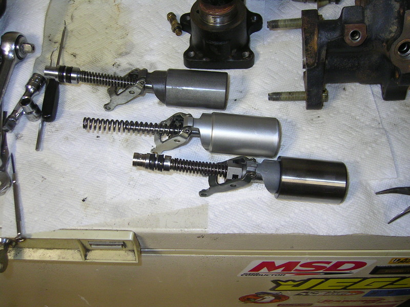
Top...Chevy, Middle...Dodge, Bottom...Astro Van.
Another thing about pistons, and perhaps this is specific to aluminum vs steel, or maybe not? The depth within the piston itself where the pushrod to the MC rides, is shorter on the Astro Van steel piston compared with both the aluminum pistons. So you can not mix and match pistons and push rods at a whim like I thought I could.
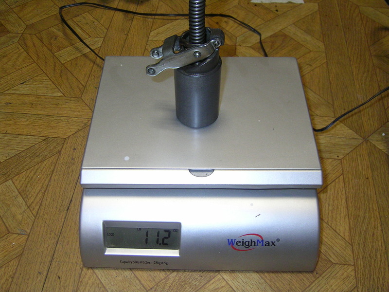
Here is the weight differences in the pistons....
Astro Van (Steel)
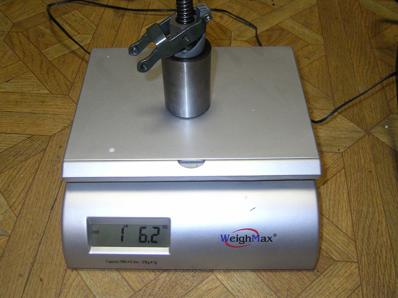
Dodge (Aluminum)
Chevy (Aluminum)
Turns out there are several differences that I was not aware of. So if you are piecing together a hydroboost unit, or have damaged/lost a part within the system, then the following info might save you some time and headaches.
Seems there are two different types of pistons, one steel, and one aluminum. My 2000 Cummins HB had an aluminum piston, and the 1995 Astro Van HB unit had a steel piston. So I went back to the wrecker to find another aluminum unit, and pulled one from a mid 90's Chevy 3500 truck...and it had an aluminum piston as well.

Top...Chevy, Middle...Dodge, Bottom...Astro Van.
Another thing about pistons, and perhaps this is specific to aluminum vs steel, or maybe not? The depth within the piston itself where the pushrod to the MC rides, is shorter on the Astro Van steel piston compared with both the aluminum pistons. So you can not mix and match pistons and push rods at a whim like I thought I could.
Here is the weight differences in the pistons....
Astro Van (Steel)

Dodge (Aluminum)

Chevy (Aluminum)
 11-08-2015, 11:37 PM
#3
Registered User
Thread Starter
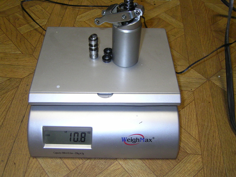
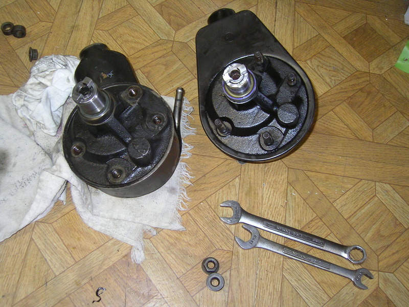
Now the differences in weight between the two Aluminum units got me to wondering why one was heavier then the other, both aluminum pistons were visibly the same, so why the difference? Well I discovered this little bit of info next.
Seems there are at least three (3) different size collars...the collar on the end of the piston assembly that the actual push rod is staked into.
Here are the 3 sizes I had.....
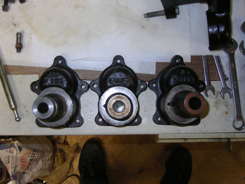
Left...smallest was from the dodge unit.
Center...medium was from the Astro Van
Right...Large was from the Chevy
Each of these require the proper tailshaft assembly to work with the proper piston/collar.
Since I only grabbed the piston from the wrecker I had to rush out the next day hoping that it had not been scrapped the night before...thankfully it was still there and I was able to procure the proper tailshaft.
11-08-2015, 11:48 PM
#5
Registered User
Thread Starter
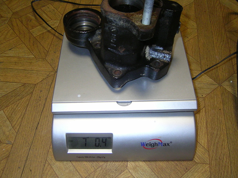
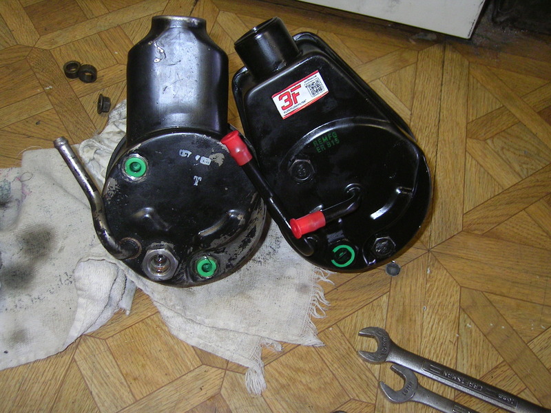
Another thing I learned, this time not so critical, is that the casting of the bodies differ slightly. The Dodge unit had some extra/thicker casting, compared to the Astro Van unit.
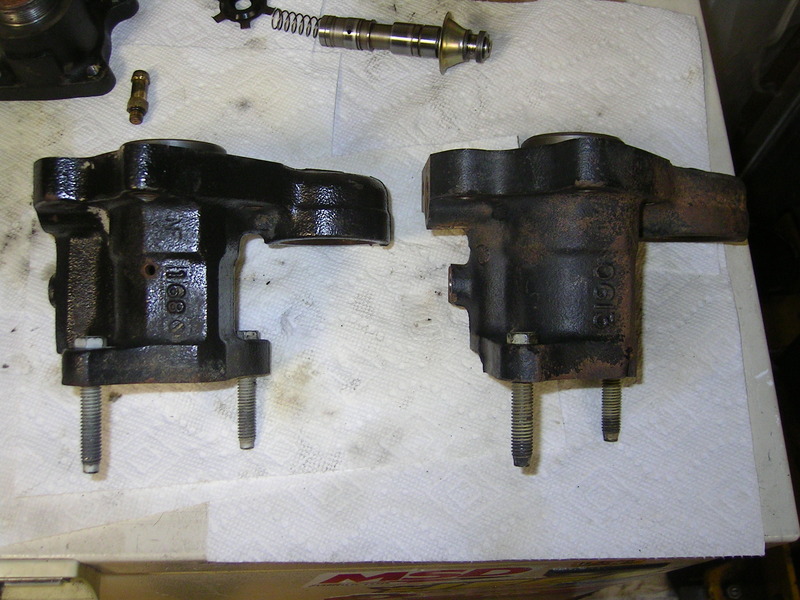
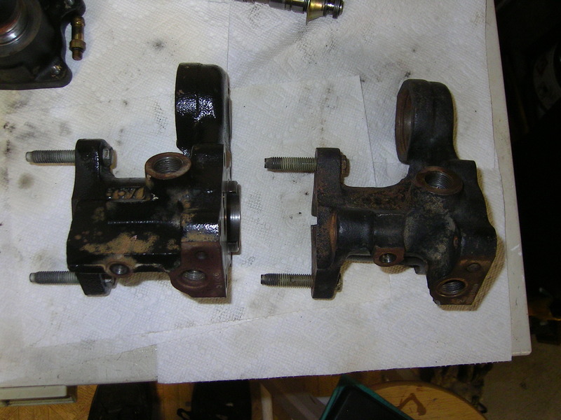
Also the Dodge unit had a MC weep hole mid casting, where as the Astro Van unit had a weep hole right where the MC bolt up.
Here is the weight difference between the two....
Astro Van
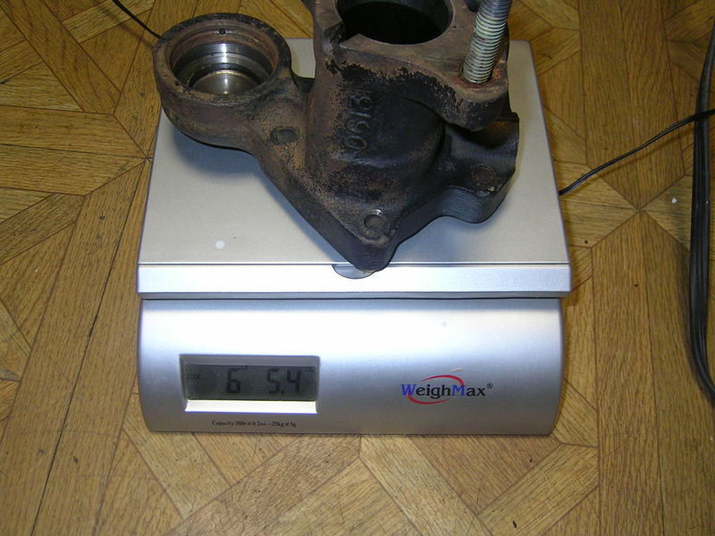
Dodge


Also the Dodge unit had a MC weep hole mid casting, where as the Astro Van unit had a weep hole right where the MC bolt up.
Here is the weight difference between the two....
Astro Van

Dodge
 11-08-2015, 11:55 PM
#6
Registered User
Thread Starter
And the last difference I found was in the return line fittings. The Astro Van had a restricted fitting compared to the Dodge unit.

I first thought that this was for better flow through the Dodge unit, but during my inspection of the differences in the main casting I discovered that the Dodge main casting has the same restriction, but it was machined into the body, not in the return line fitting.
So that concludes this portion of the thread.....the Fact finding portion....be it through trial and error, dumb luck or desperation.
11-09-2015, 12:08 AM
#7
Registered User
Thread Starter
OK now to the installtion on my truck.....
First off I wanted to use as much of the 2000 Cummins system I could, lines included. But did not want the big firewall bracket. The Astro Van unit provided the perfect swap since it's firewall bracket is a direct swap onto the 1st Gen firewall....no mods required (if you use all GM stuff)....almost.
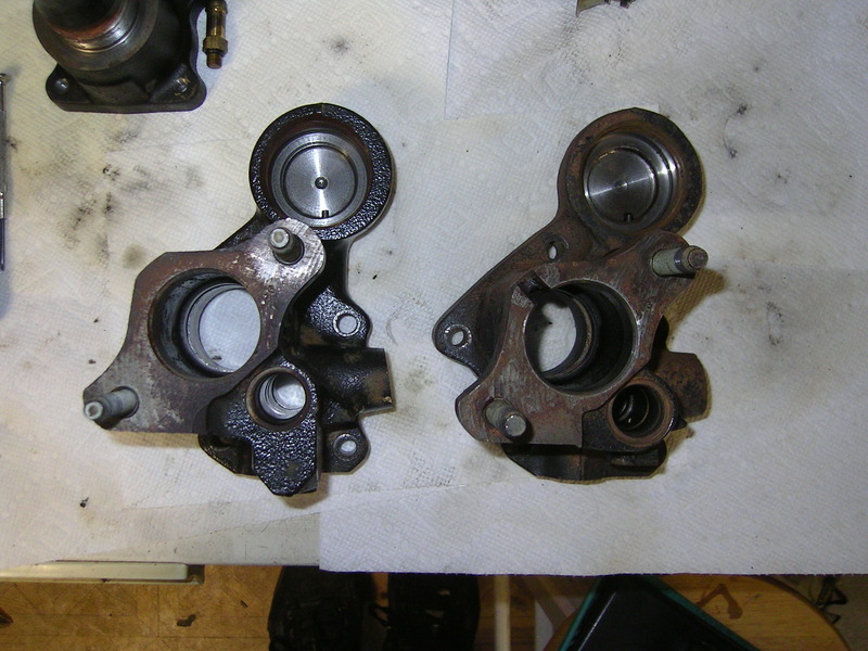
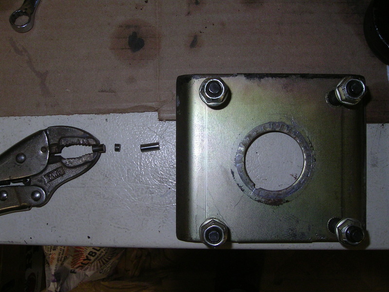
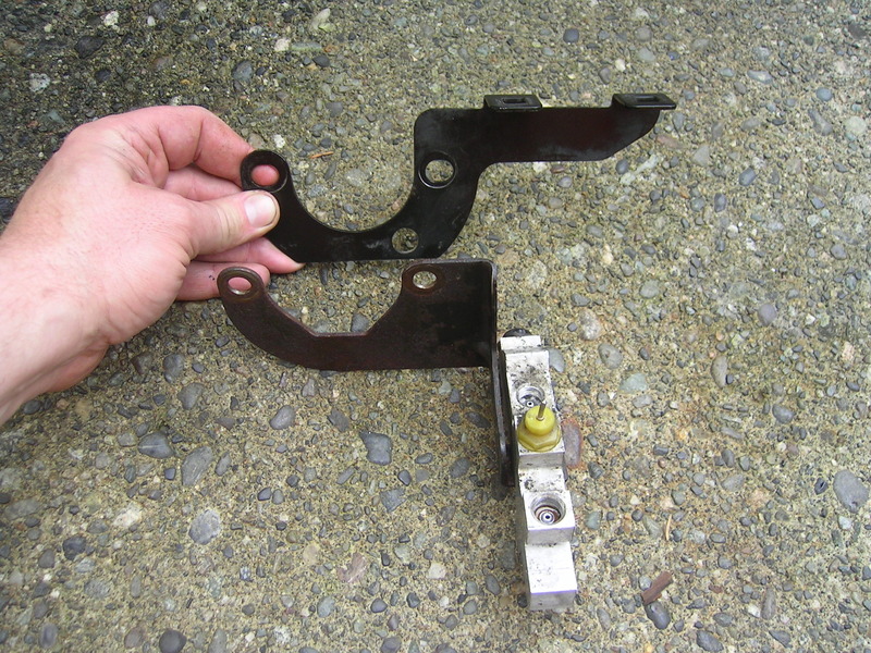
Since I wanted to use the Dodge assembly I had to alter the alignment if the HB unit, since Dodge uses a master cylinder adapter bracket the turns the HB about 45* clockwise.
Dodge vs Astro Van.....you can see the alignment tab location differs.
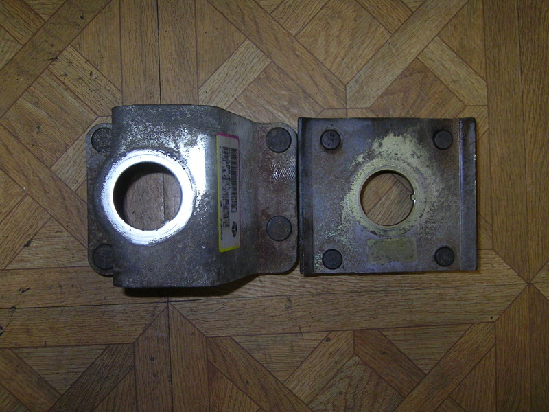
And my solution to the alignment.
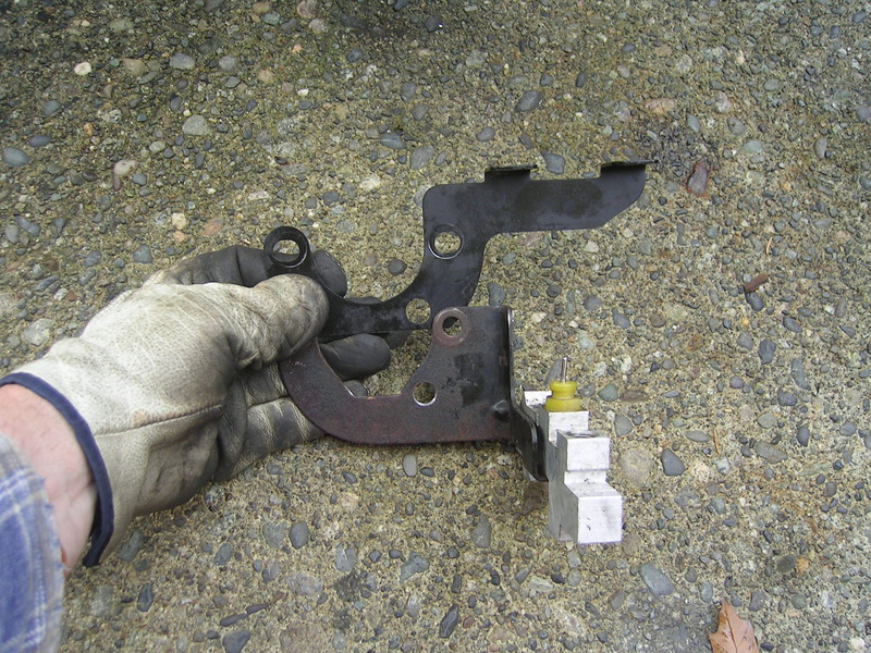
I measured everything out and located where the new tab would be located on the Astro van bracket. I was going to weld up the area then hand file it to fit, but once I started removing some material for the weld to bite into I noticed that perhaps there was another way.
I put the bracket on the tailshaft and noticed that perhaps I could use something as a keyway? Started wandering around the shop and came across some roller bearings from either my NV4500 or NP205 rebuild. Tried one and it fit perfect, just had to cut it to length!
I measured everything out and located where the new tab would be located on the Astro van bracket. I was going to weld up the area then hand file it to fit, but once I started removing some material for the weld to bite into I noticed that
First off I wanted to use as much of the 2000 Cummins system I could, lines included. But did not want the big firewall bracket. The Astro Van unit provided the perfect swap since it's firewall bracket is a direct swap onto the 1st Gen firewall....no mods required (if you use all GM stuff)....almost.
Since I wanted to use the Dodge assembly I had to alter the alignment if the HB unit, since Dodge uses a master cylinder adapter bracket the turns the HB about 45* clockwise.
Dodge vs Astro Van.....you can see the alignment tab location differs.

And my solution to the alignment.
I measured everything out and located where the new tab would be located on the Astro van bracket. I was going to weld up the area then hand file it to fit, but once I started removing some material for the weld to bite into I noticed that perhaps there was another way.
I put the bracket on the tailshaft and noticed that perhaps I could use something as a keyway? Started wandering around the shop and came across some roller bearings from either my NV4500 or NP205 rebuild. Tried one and it fit perfect, just had to cut it to length!


I measured everything out and located where the new tab would be located on the Astro van bracket. I was going to weld up the area then hand file it to fit, but once I started removing some material for the weld to bite into I noticed that
Trending Topics
11-09-2015, 12:19 AM
#8
Registered User
Thread Starter
Then it was rebuild and reseal time. I won't go into what I did to redo my HB unit...since I followed this thread to the letter.
Hydroboost reseal tutorial (long)
Follow this one and you can't go wrong.
All done...
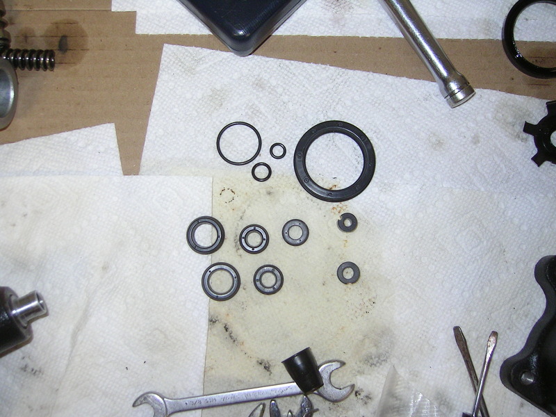
I purchased a re-seal kit from E-bay seller "Pirate jack" part # 2771004X or 2771004. You'll have a few O-rings left over from the rebuild.
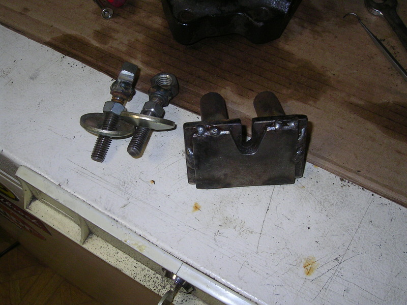
And installing the firewall bracket.
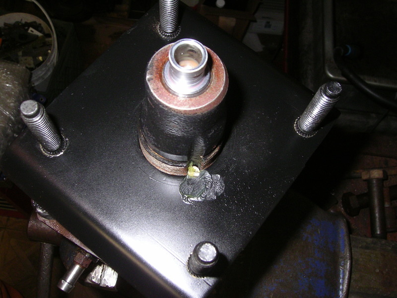
And how do you tighten up that 4 sided nut....I used brass punches and a hammer to get it loose, but this wouldn't work to tighten. Finally came across my grandfathers old chain wrench...worked like a champ!
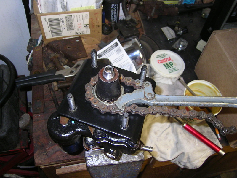
Highly recommend this for removal, and installation of that nut.
11-09-2015, 12:29 AM
#9
Registered User
Thread Starter
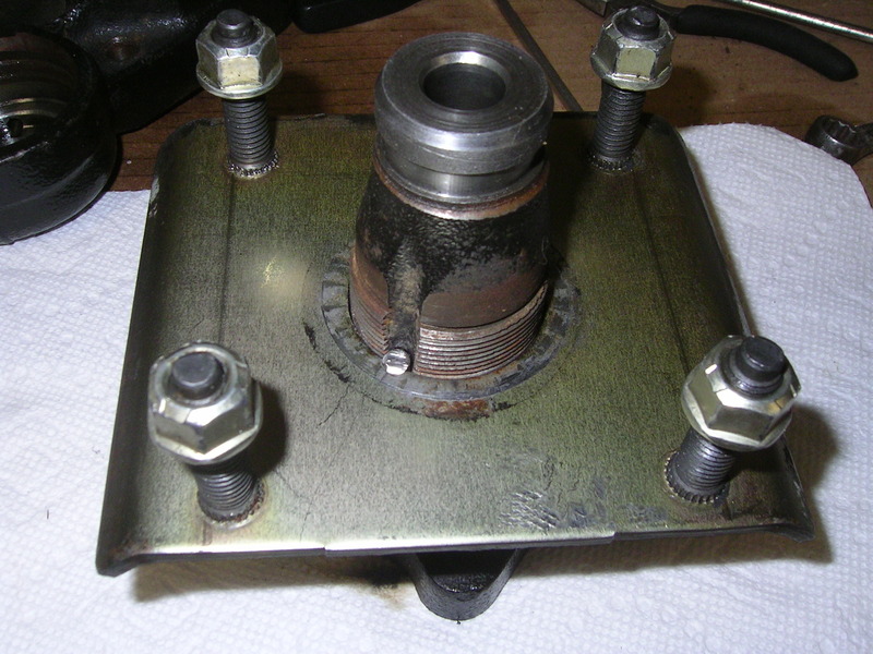
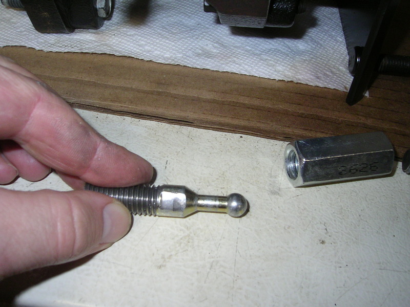
Then all that was left was to make up an adjustable pedal to HB pushrod. I took the ball end off the dodge HB, and cut off the push rod from an old vacuum booster. Then cut each to about 2.35 inches in length, and then threaded each 1/2 x 13 NC. Got a coupler and a jam but and was done.
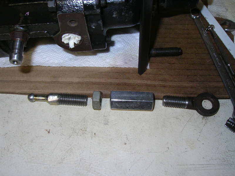
I also filed two flat sides on the dodge ball end so I could use a crescent wrench to hold it while working on things.
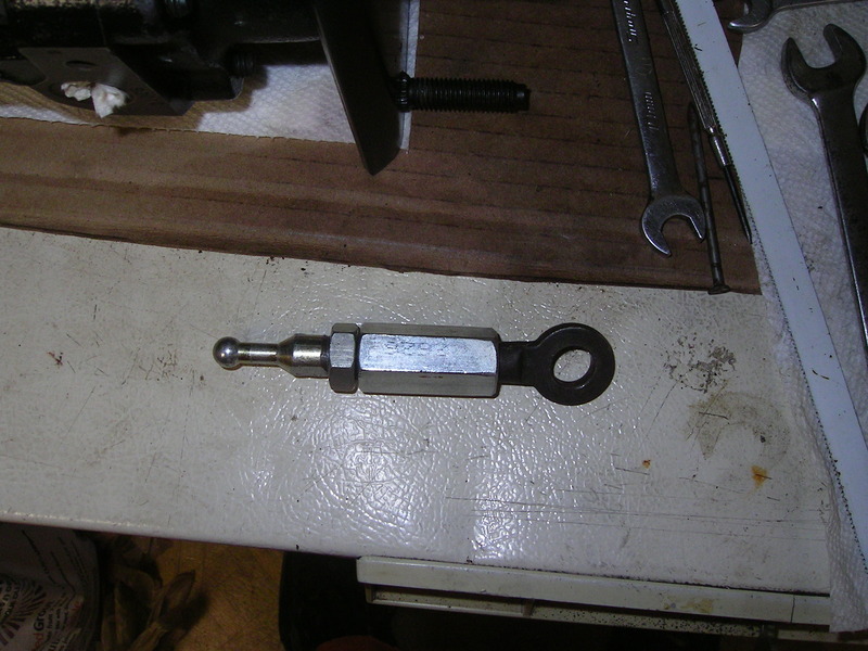
Then used a big rubber hammer to band the pushrod back in. Used a flat chisel and a block of wood to re-stake the push rod.

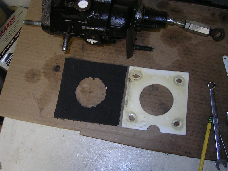
You can also see the foam/neoprene gasket I made. Just used an old gasket and traced it out on a sheet of the material then cut it out. It is sticky once side so just peal and stick in place!

I also filed two flat sides on the dodge ball end so I could use a crescent wrench to hold it while working on things.


Then used a big rubber hammer to band the pushrod back in. Used a flat chisel and a block of wood to re-stake the push rod.

You can also see the foam/neoprene gasket I made. Just used an old gasket and traced it out on a sheet of the material then cut it out. It is sticky once side so just peal and stick in place!
 11-09-2015, 12:39 AM
#10
Registered User
Thread Starter
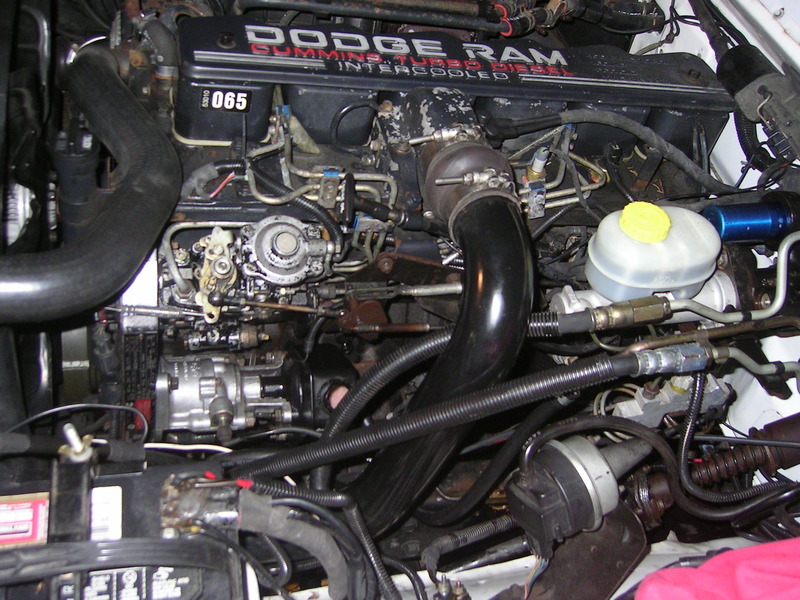
This is what I started with this morning....
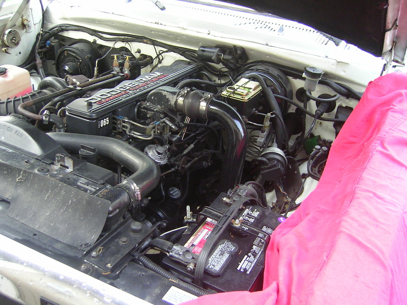
Didn't take long to end up with the HB unit mounted to the firewall.
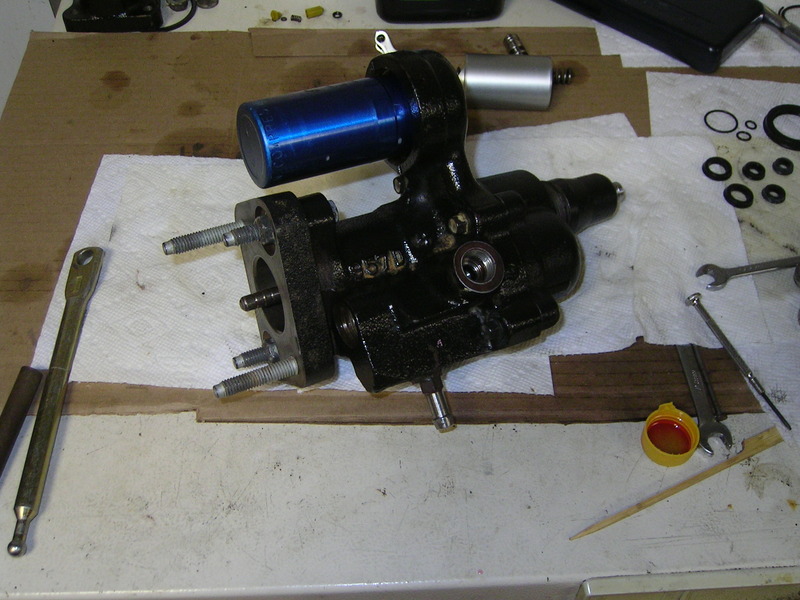
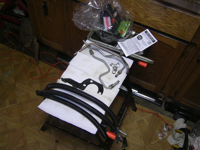
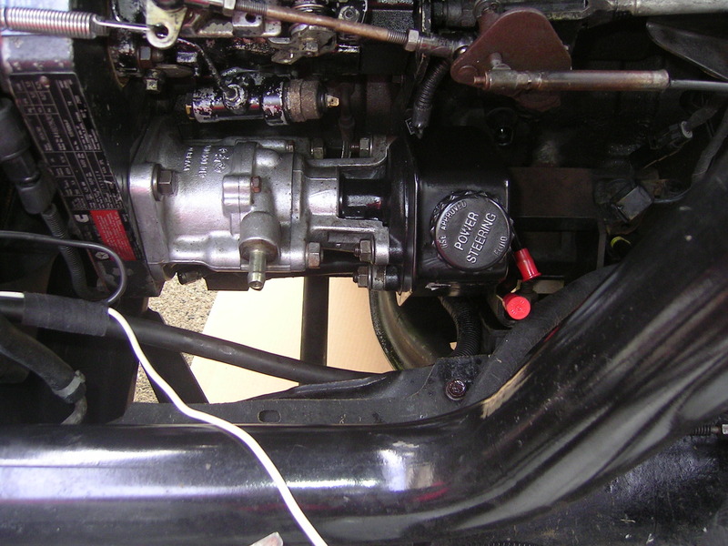
Here is pretty much everything else in the system. New PS Pump for a 2000 Cummins. Good used high pressure lines and new 3/8 PS hose and clamps, brackets etc.
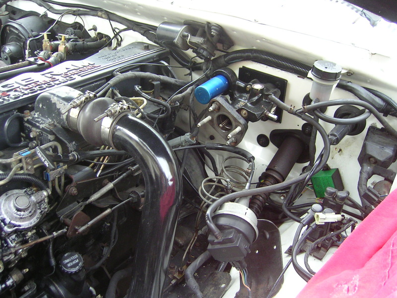
Now the fun began....
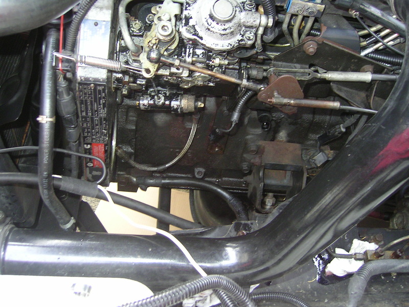
I lie to just pull the vacuum/PS assembly out to work on it, or if I'm doing an injection pump re/re. Only takes about 10 min to pop it out, and you will never accidentally break off your oil pressure sending unit either.

Didn't take long to end up with the HB unit mounted to the firewall.

Here is pretty much everything else in the system. New PS Pump for a 2000 Cummins. Good used high pressure lines and new 3/8 PS hose and clamps, brackets etc.

Now the fun began....
I lie to just pull the vacuum/PS assembly out to work on it, or if I'm doing an injection pump re/re. Only takes about 10 min to pop it out, and you will never accidentally break off your oil pressure sending unit either.

 11-09-2015, 12:50 AM
#11
Registered User
Thread Starter
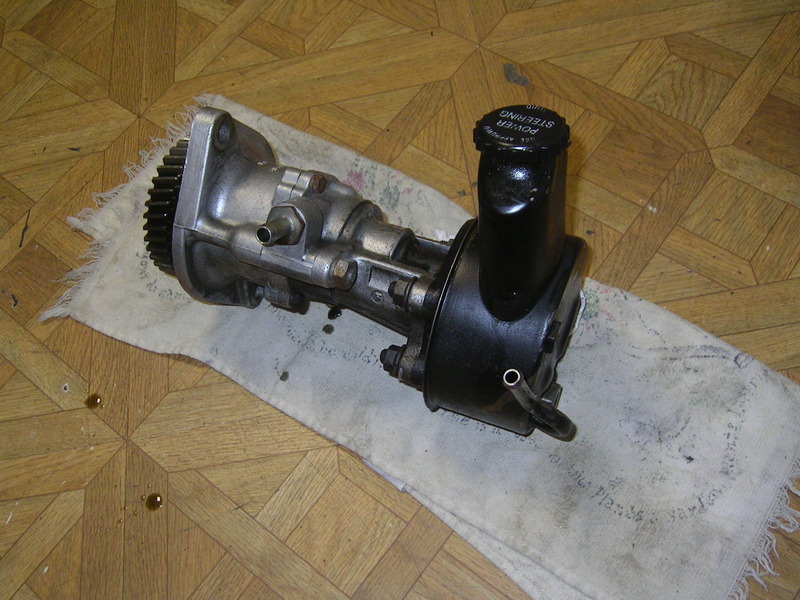
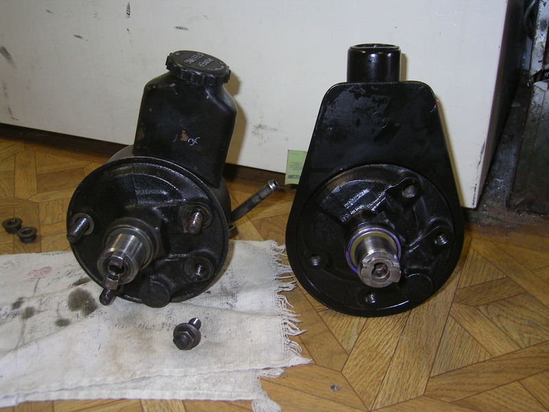
Little bit of work to put the new PS pump on. You have to swap the 4 mounting studs on the front, I just used two of the 15mm bolts tightened/locked together to spin them out and move them over.
Then swap the 2 - 18mm bolts in the back of the case over to the new unit.

Now just remount the PS pump onto the Vacuum pump...don't forget the two spacers...and re-install on the motor.


Then swap the 2 - 18mm bolts in the back of the case over to the new unit.


Now just remount the PS pump onto the Vacuum pump...don't forget the two spacers...and re-install on the motor.
 11-09-2015, 12:56 AM
#12
Registered User
Thread Starter
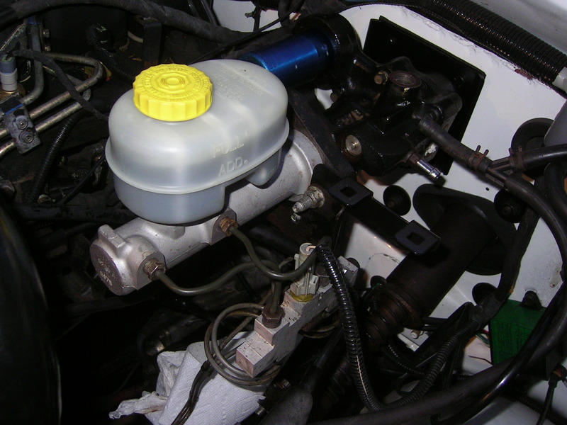
Put the MC in place...
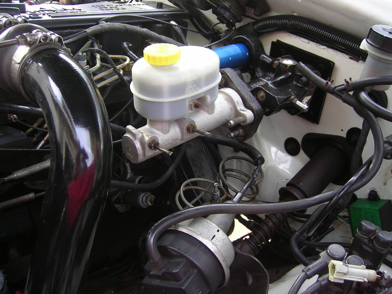
And discovered that the bracket for the metering block fit perfectly...not modifications required (unlike the GM unit). Only had to drill one new hole to clear the adapter plate mounting bolt.
Got to this point and then was informed by my family that my presence was required to go watch a movie at the theater..... 

And discovered that the bracket for the metering block fit perfectly...not modifications required (unlike the GM unit). Only had to drill one new hole to clear the adapter plate mounting bolt.


Got to this point and then was informed by my family that my presence was required to go watch a movie at the theater.....
11-09-2015, 01:02 AM
#13
Registered User
Thread Starter
About 4 hours later I was back at it...
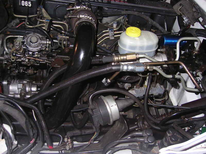
I had to put in new brake lines from the MC to the metering block, since the MC runs metric fittings, and the old lines would not fit regardless. I am no tube bender....I hacked those things into place...ugly as sin, but they function fine.
Then install the OEM lines...
I had to put in new brake lines from the MC to the metering block, since the MC runs metric fittings, and the old lines would not fit regardless. I am no tube bender....I hacked those things into place...ugly as sin, but they function fine.

Then install the OEM lines...

 11-09-2015, 01:11 AM
#14
Registered User
Thread Starter
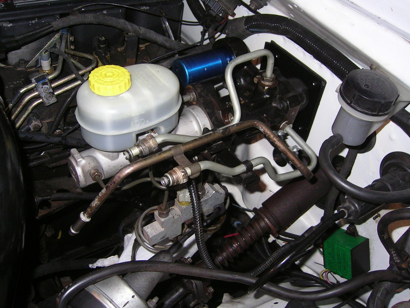
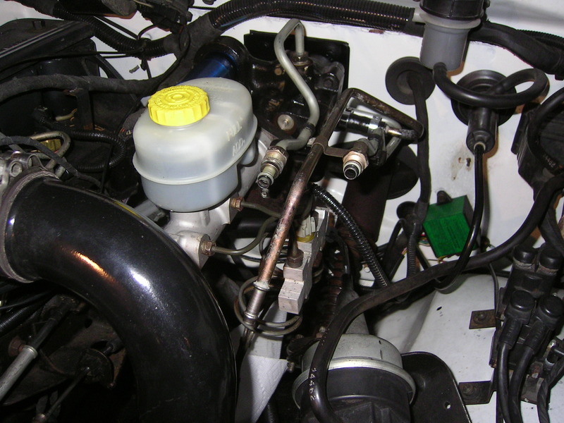
Then install the High pressure lines, and return lines.
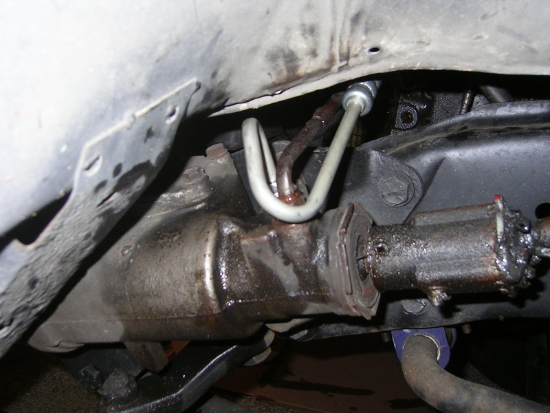
The steering box was the toughest. due to the OEM bends in the line it was a tough fit to clear the return line. But after removing the inner splash shield I was able to get it all lined up.
Then it was follow the priming/starting instructions from the rebuild thread posted earlier.
Took the crewcab for a short drive...since it was getting late....and the brakes feel so much better!


The steering box was the toughest. due to the OEM bends in the line it was a tough fit to clear the return line. But after removing the inner splash shield I was able to get it all lined up.

Then it was follow the priming/starting instructions from the rebuild thread posted earlier.
Took the crewcab for a short drive...since it was getting late....and the brakes feel so much better!
11-09-2015, 05:44 AM
#15
Wow...at last! Great job! Very detail oriented. 1st "How To" post I've read that outlines in full detail mistakes made and the results that follow! You even posted up links to additional assisting Threads and made this something a simpleton like myself could do! Thanks for all your work, and the detailed photos. So, I gotta ask, what movie did you go see with the family?