Repairing your instrument cluster & install LED's
 07-02-2008, 07:09 AM
#1
Administrator
Thread Starter

Part-1
Repairing Instrument cluster and install LED’s.
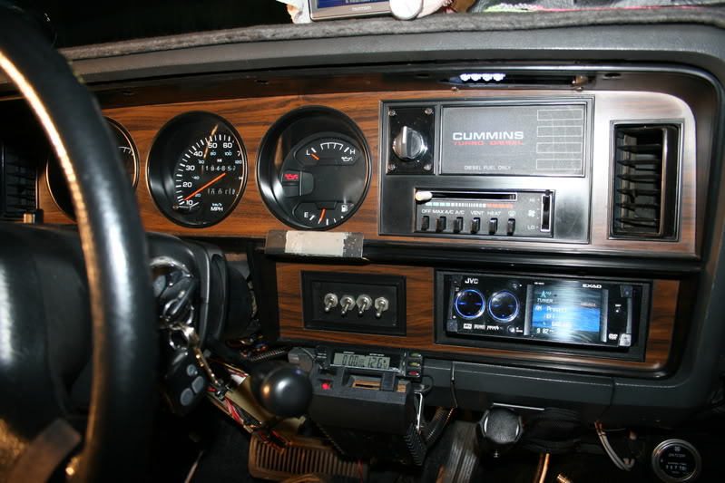
If your truck is anything like mine, the speedometer and gauges are not the easiest to read when the sun goes down.
Also for some time I have had some of the gauges doing mysterious things as I drive, the needle of the Fuel and Temp gauge would drift lazily back and fourth and then come back and stop back to the normal ranges or I think?
So this project will be to,
Clean and repair the instrument cluster
Replace the incandesant lamps with LED’s
Repair the grounding issues.
First, BLOCK both rear wheels of the truck and Apply the parking brake.
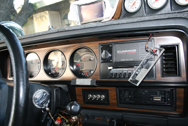
To begin you will have to remove the cluster from the dash so start by removing the 6 screws that retain the bezel to the dash, there will be 5 screws along the top and 1 screw just above the radio.
Also remove the map light and let it hang by the wires.
You will also need to remove the trim that secures the fuse panel by removing the 4 screws and drop it away.
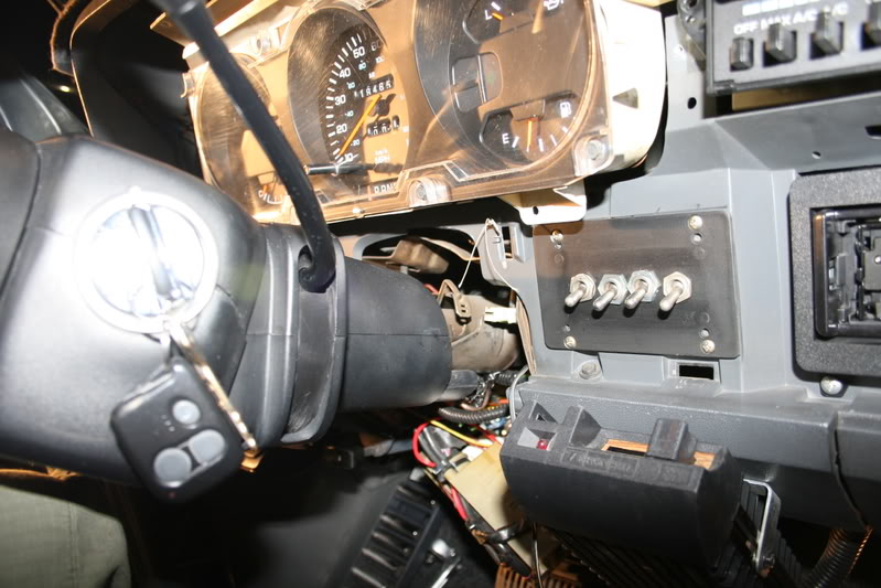
Next move the shifter downwards and from the right side using a pair of needle nosed pliers or Hemostats after making a note the slot the PRND21 Shift Indicator control line is in, carefully remove the hook from the bracket.
I found it easiest if you tie about 6” of heavy fishing line to the end of the hook making it easy to manipulate, leave this string attached when you are finished.
Then using a 7/16” deep socket, loosen and back out the 2 nuts on either side of the column while holding the steering wheel between your knees, moving the shifter in D or lower, you can now remove the bezel from the dash, there will be I think 6 clips along the lower edge of the bezel, just pull back and it will come loose.
Retrieve all of the clips once it is out.
Feed the Map Light and wires back out through the hole and remove the bezel to a safe place.
Now to remove the insturment cluster you will have to remove 6 Phillips head screws along the top, bottom and right side.
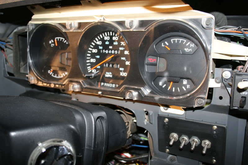
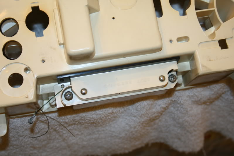
Here all of the screws are removed and you can see where the control line for the PRND21 was connected to the bracket with the string attached.
Be careful not to bend the indicator bracket or the shift indicator will not indicate the gear correctly.
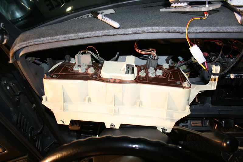
Next remove the 2 screws retaining the heater/ AC panel to the dash, there is no need to remove it, but just pull it straight out about ˝” so the right corner of the cluster will come free and then pull back on the cluster.
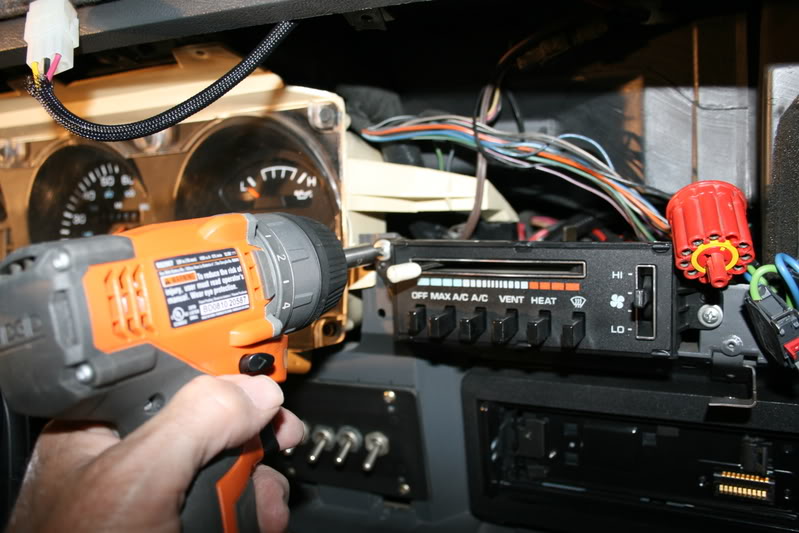
Now rotate the top backwards towards you to reach the connectors.
It is going to be dirty back there.
Go ahead and remove the 2 connectors, there will be 1 flat one and 1 round one.
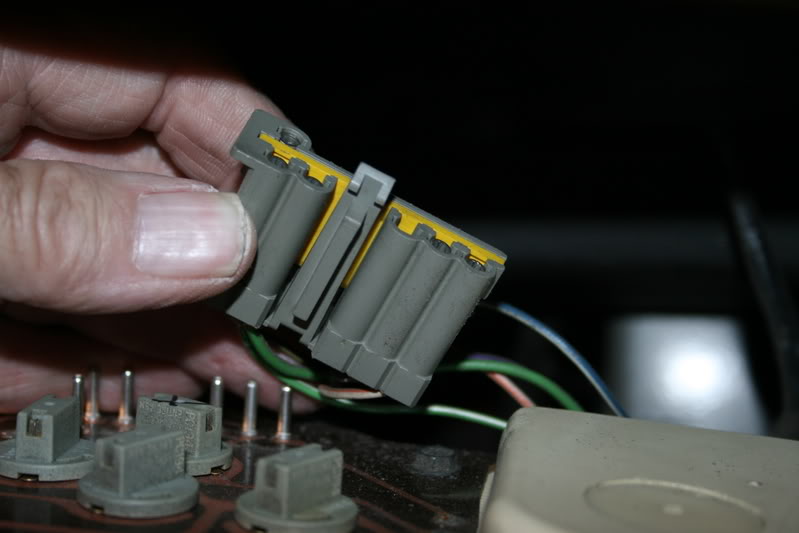
The round connector will just pull straight off while the Flat connector you will need to reach around to the back of it and press in on the retaining clip and then you can pull it straight off.
Here is what the backside of the Flat connecter will look like, just feel for it and press it in.
Now remove the instrument cluster and move it to a clean working location and lay it face down on a soft towel so to not scratch the clear plastic faceplate.
Be very careful with the odometer reset button that you do not push down too hard and break it off.
It would be best if you were to raise up the cluster with something under the towel to protect the button, or just be careful.
Remove the 7 screws from the back that retains the circuit board and then carefully pull the board loose from the gauges, there will be pins that electrically connect the gauges to the circuit board, just pull them straight off.
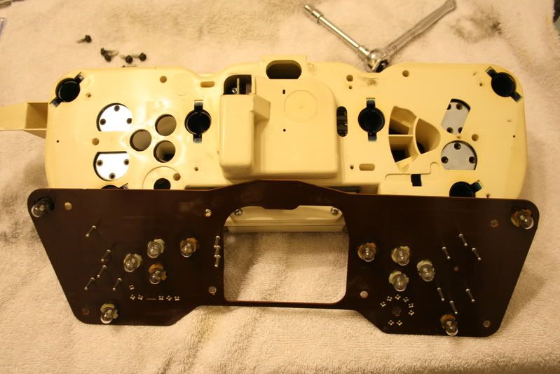
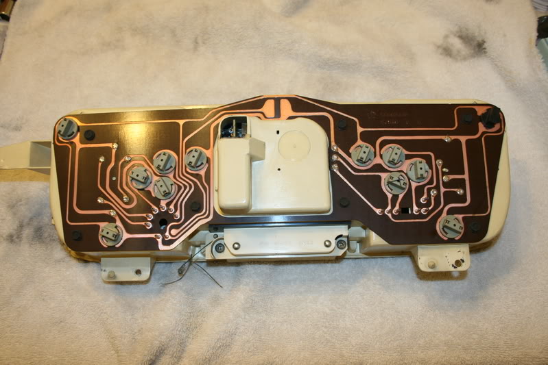
Here is the backside of the cluster; I made a quick diagram of what lights go where.
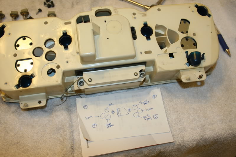
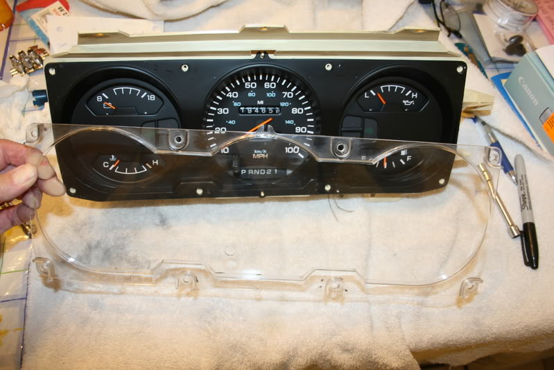
Now turn it over and remove the 6 screws that retain the clear plastic cover to the housing.
Repairing Instrument cluster and install LED’s.
If your truck is anything like mine, the speedometer and gauges are not the easiest to read when the sun goes down.
Also for some time I have had some of the gauges doing mysterious things as I drive, the needle of the Fuel and Temp gauge would drift lazily back and fourth and then come back and stop back to the normal ranges or I think?
So this project will be to,
Clean and repair the instrument cluster
Replace the incandesant lamps with LED’s
Repair the grounding issues.
First, BLOCK both rear wheels of the truck and Apply the parking brake.
To begin you will have to remove the cluster from the dash so start by removing the 6 screws that retain the bezel to the dash, there will be 5 screws along the top and 1 screw just above the radio.
Also remove the map light and let it hang by the wires.
You will also need to remove the trim that secures the fuse panel by removing the 4 screws and drop it away.
Next move the shifter downwards and from the right side using a pair of needle nosed pliers or Hemostats after making a note the slot the PRND21 Shift Indicator control line is in, carefully remove the hook from the bracket.
I found it easiest if you tie about 6” of heavy fishing line to the end of the hook making it easy to manipulate, leave this string attached when you are finished.
Then using a 7/16” deep socket, loosen and back out the 2 nuts on either side of the column while holding the steering wheel between your knees, moving the shifter in D or lower, you can now remove the bezel from the dash, there will be I think 6 clips along the lower edge of the bezel, just pull back and it will come loose.
Retrieve all of the clips once it is out.
Feed the Map Light and wires back out through the hole and remove the bezel to a safe place.
Now to remove the insturment cluster you will have to remove 6 Phillips head screws along the top, bottom and right side.
Here all of the screws are removed and you can see where the control line for the PRND21 was connected to the bracket with the string attached.
Be careful not to bend the indicator bracket or the shift indicator will not indicate the gear correctly.
Next remove the 2 screws retaining the heater/ AC panel to the dash, there is no need to remove it, but just pull it straight out about ˝” so the right corner of the cluster will come free and then pull back on the cluster.
Now rotate the top backwards towards you to reach the connectors.
It is going to be dirty back there.
Go ahead and remove the 2 connectors, there will be 1 flat one and 1 round one.
The round connector will just pull straight off while the Flat connector you will need to reach around to the back of it and press in on the retaining clip and then you can pull it straight off.
Here is what the backside of the Flat connecter will look like, just feel for it and press it in.
Now remove the instrument cluster and move it to a clean working location and lay it face down on a soft towel so to not scratch the clear plastic faceplate.
Be very careful with the odometer reset button that you do not push down too hard and break it off.
It would be best if you were to raise up the cluster with something under the towel to protect the button, or just be careful.
Remove the 7 screws from the back that retains the circuit board and then carefully pull the board loose from the gauges, there will be pins that electrically connect the gauges to the circuit board, just pull them straight off.
Here is the backside of the cluster; I made a quick diagram of what lights go where.
Now turn it over and remove the 6 screws that retain the clear plastic cover to the housing.
 07-02-2008, 07:10 AM
#2
Administrator
Thread Starter
Part-2
After you remove the cover then carefully remove the black bezel from the top of the gauges and set it aside.
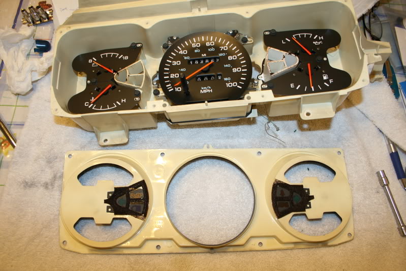
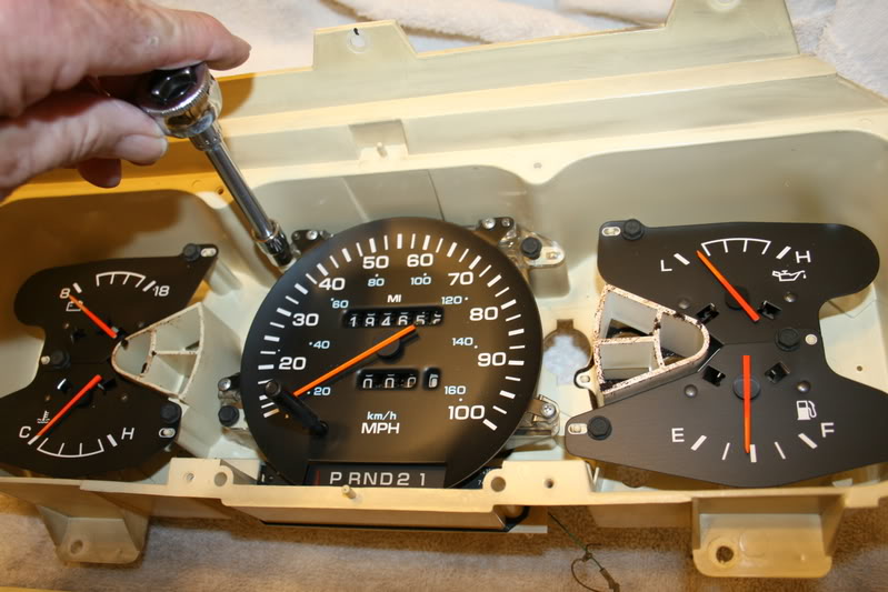
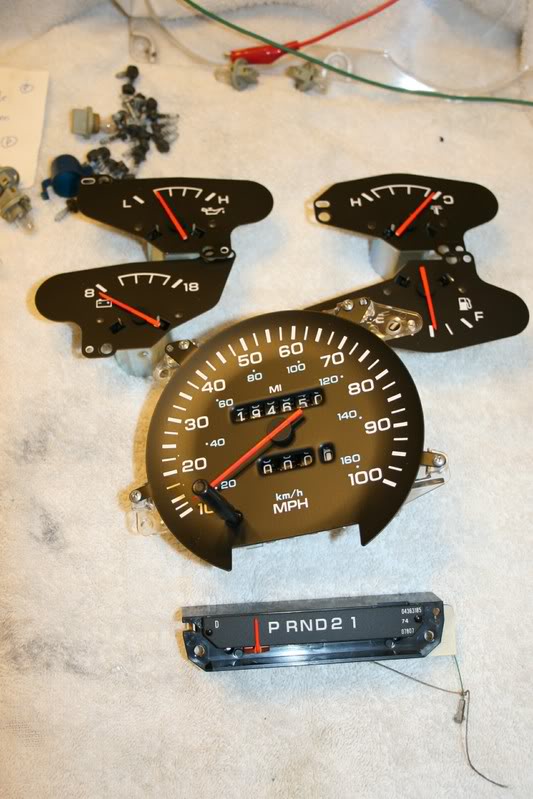
Then remove the 9 hex head bolts from the faceplates that secure each individual gauge into the housing.
From the backside remove the 2 Phillips head screws that retain the shift indicator and remove it from the housing.
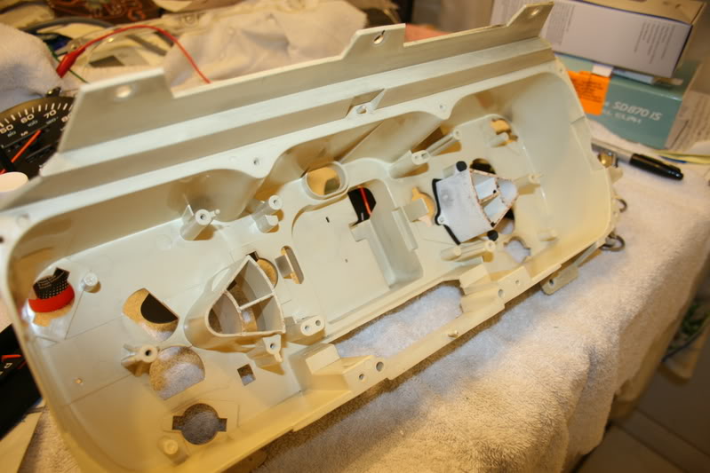
You should now have an empty housing, from here you will need to clean out all of the dust and black smudge marks from the heat of the old lamps.
I used a soft lint free towel and some Windex and took my time to get it out of every corner.
When you are finished you should have a nice and clean housing.
Now comes the special part of this modification that sets mine apart from the others.
On the inside of the housing you will cover the inside of the housing using some Aluminum Foil Tape that is commonly used in the HVAC field, you can get this at Home Depot and is more useful then Duct Tape.
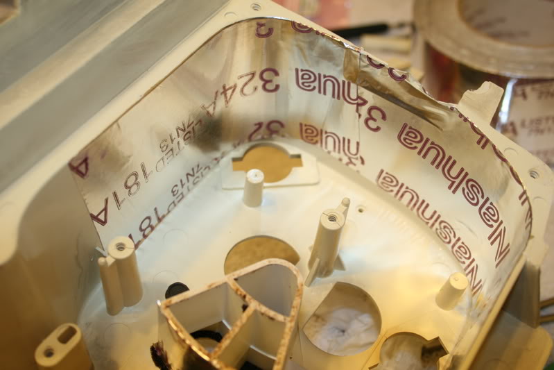
After you have it installed, then using a rag you will smooth it down along all of the corners.
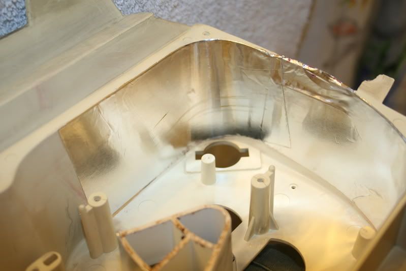
Once it is smooth you then take a paper towel soaked with Lacquer Thinner quickly wipe it down and it will remove all of the writing and leave a nice shiny reflective surface, take care as not to wipe the plastic housing with the Lacquer Thinner.
Then I spent some time on the actual gauges. I used a soft lint free towel and sprayed it with Windex and then carefully wiped down the faceplates and the needle of each unit.
Use just enough on the rag to clean them and do not spray it directly onto the faceplate or the writing may come off.
Again, Do not rub them hard.
Then I touched up the paint on each needle, what I did was to spray some Florescent Red Paint onto a paper plate and then using a small paint brush repaint each needle using long brush strokes the length of the needle.
Protect the faceplate using a piece of aluminum foil slid under the needle.
I painted each needle about 4 times allowing the previous coat to dry for about 10 minuets leaving them a bright florescent red in color.
I had tried various other paints from the craft store but none of them gave me the color I wanted.
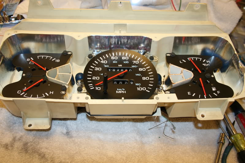
Now it is time to reassemble the gauges back into the housing.
At this time I had already repaired my odometer and had installed the 2 broken gears that are the common weak point of the VDO speedometer.
Incase you have not figured it out by now; the foil tape is to create a reflector for the lights and intensify the light to illuminate the gauges.
Make sure you have installed the foil to the curved area of the housing adjacent to the speedometer dial.
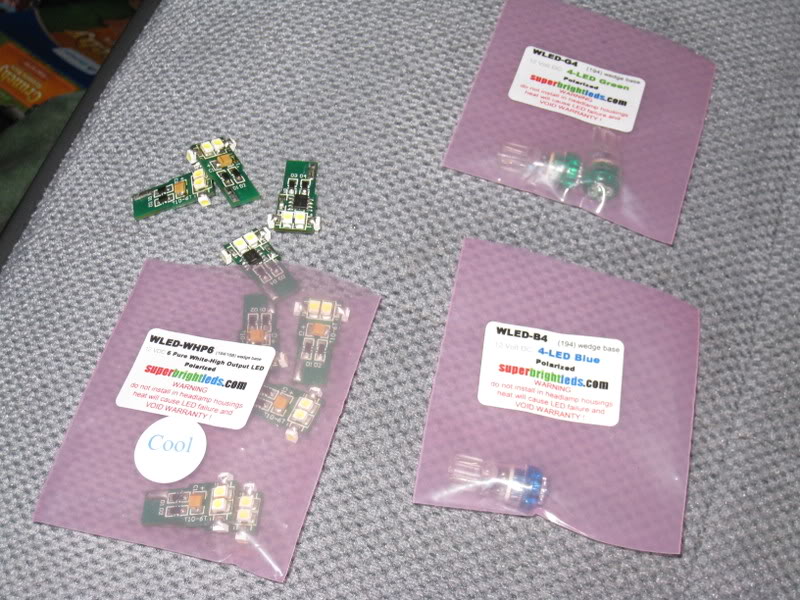
Now when it comes to the lighting, I chose to use the LED’s from superbrightleds.com
Doing some research I feel they are the brightest ones and the Cool White will give the color I am looking for.
Each module has 6 die mounted radially and simulates the #194 perfectly and team these with the newly added reflector the light will be distributed evenly around the housing.
I will also replace the Directional Signal and High Beam indicators at this time using a Quad LED.
Also I chose not to remove the colored domes from the housing to help shift the output color more into the green/ blue region.
Now that I have al of the LED’s installed I connected it to a gel cell and checked all of the lamps for their operation and this also gave me the opportunity to make sure my reflectors are in the correct position.
Remember that these LED’s are polarized so if they do nor work then you simply turn them 180* and reinsert them.
Another important bit of information, Dodge had installed the lamps in the cluster using a 1 piece lamp and holder, if you have these, you will need to get some replacement ˝” sockets from your local auto parts.
More on this at the end of this article.
Well what do you think so far?

After you remove the cover then carefully remove the black bezel from the top of the gauges and set it aside.
Then remove the 9 hex head bolts from the faceplates that secure each individual gauge into the housing.
From the backside remove the 2 Phillips head screws that retain the shift indicator and remove it from the housing.
You should now have an empty housing, from here you will need to clean out all of the dust and black smudge marks from the heat of the old lamps.
I used a soft lint free towel and some Windex and took my time to get it out of every corner.
When you are finished you should have a nice and clean housing.
Now comes the special part of this modification that sets mine apart from the others.
On the inside of the housing you will cover the inside of the housing using some Aluminum Foil Tape that is commonly used in the HVAC field, you can get this at Home Depot and is more useful then Duct Tape.
After you have it installed, then using a rag you will smooth it down along all of the corners.
Once it is smooth you then take a paper towel soaked with Lacquer Thinner quickly wipe it down and it will remove all of the writing and leave a nice shiny reflective surface, take care as not to wipe the plastic housing with the Lacquer Thinner.
Then I spent some time on the actual gauges. I used a soft lint free towel and sprayed it with Windex and then carefully wiped down the faceplates and the needle of each unit.
Use just enough on the rag to clean them and do not spray it directly onto the faceplate or the writing may come off.
Again, Do not rub them hard.
Then I touched up the paint on each needle, what I did was to spray some Florescent Red Paint onto a paper plate and then using a small paint brush repaint each needle using long brush strokes the length of the needle.
Protect the faceplate using a piece of aluminum foil slid under the needle.
I painted each needle about 4 times allowing the previous coat to dry for about 10 minuets leaving them a bright florescent red in color.
I had tried various other paints from the craft store but none of them gave me the color I wanted.
Now it is time to reassemble the gauges back into the housing.
At this time I had already repaired my odometer and had installed the 2 broken gears that are the common weak point of the VDO speedometer.
Incase you have not figured it out by now; the foil tape is to create a reflector for the lights and intensify the light to illuminate the gauges.
Make sure you have installed the foil to the curved area of the housing adjacent to the speedometer dial.
Now when it comes to the lighting, I chose to use the LED’s from superbrightleds.com
Doing some research I feel they are the brightest ones and the Cool White will give the color I am looking for.
Each module has 6 die mounted radially and simulates the #194 perfectly and team these with the newly added reflector the light will be distributed evenly around the housing.
I will also replace the Directional Signal and High Beam indicators at this time using a Quad LED.
Also I chose not to remove the colored domes from the housing to help shift the output color more into the green/ blue region.
Now that I have al of the LED’s installed I connected it to a gel cell and checked all of the lamps for their operation and this also gave me the opportunity to make sure my reflectors are in the correct position.
Remember that these LED’s are polarized so if they do nor work then you simply turn them 180* and reinsert them.
Another important bit of information, Dodge had installed the lamps in the cluster using a 1 piece lamp and holder, if you have these, you will need to get some replacement ˝” sockets from your local auto parts.
More on this at the end of this article.
Well what do you think so far?
07-02-2008, 07:11 AM
#3
Administrator
Thread Starter
Part-3
Now we can start to reassemble the front of the cluster, using some Windex on a soft lint free towel carefully clean the both sides of the bezel and the clear plastic lens being careful as to not leave any lint on the surface.
And then after all of the gauges are in their respective locations you can now reinstall the bezel back onto the top of the faceplates and then replace the retaining screws.
Now we will take a look at the back of the printed circuit board and all of its connections.
I have no idea why it has a Ford lamp socket.
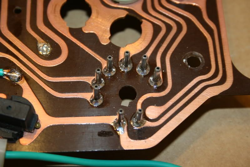
All of the connections to the gauges are passed through these staked in terminals, I have found most of my problems here since they were only pressed in and staked over.
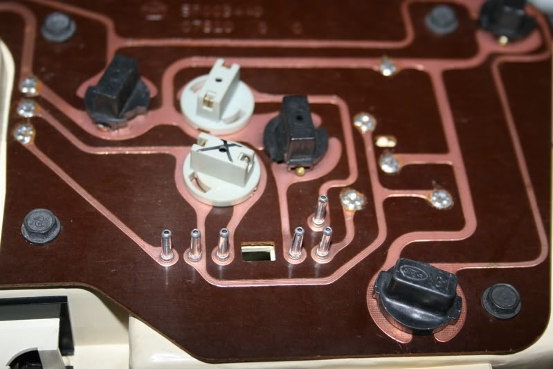
This is how they are secured to the board; so simple a Caveman can do it.
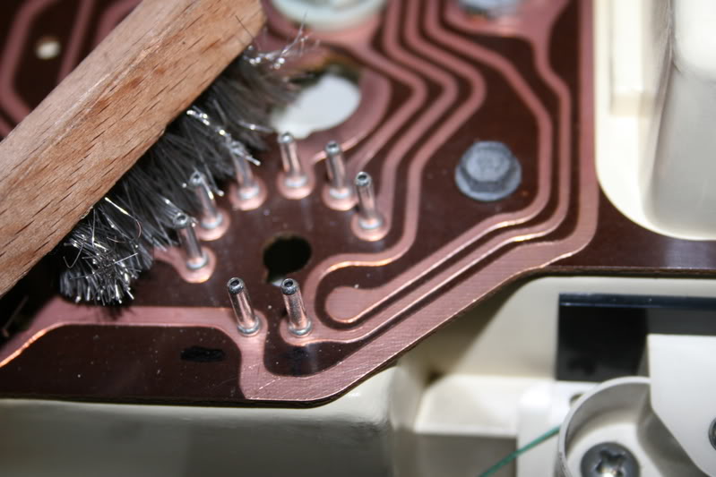
So to cure this connection problem I cleaned all of the oxidation from around each terminal and the foil on the circuit board using a stainless brush.
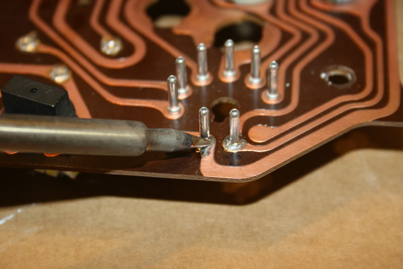
And then I again removed the circuit board from the housing as to not damage the gauges of housing from heat and then after supporting the board I carefully soldered each connection using a small 20 watt soldering iron and a good quality .020 Rosin Core Solder.
Only apply enough heat to heat the connection and then touch the solder to the connection and NOT the tip of the iron.
This will draw the solder into the joint and create a good electrical connection, I then did this to all of the connections on the board.
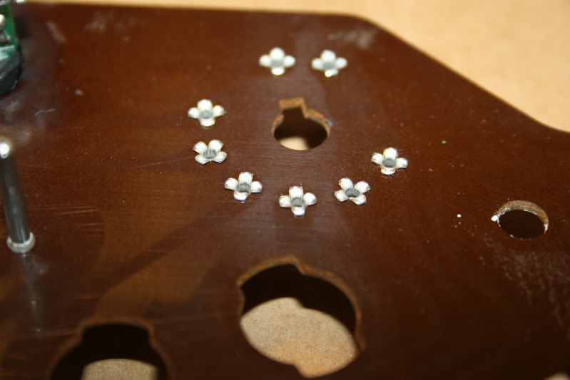
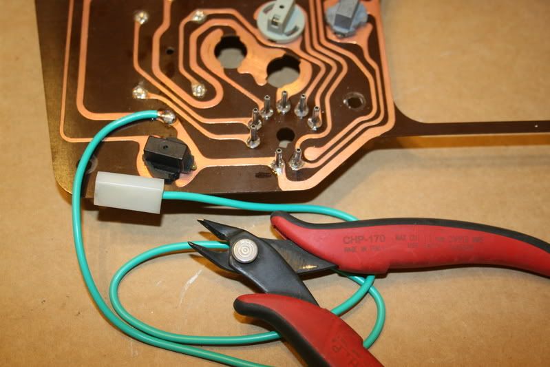
This is how it should look when you are finished, I then cleaned it up using some flux remover.
Since all of the gauges in the cluster receive their ground from the same ground connection in the harness, I provided an additional grounding point for the circuit by installing an additional ground wire directly to the circuit board trace using a length of 16-gauge wire.
At the opposite end of this wire install a sturdy .250 Female Spade terminal to be easily disconnected when the cluster needs to be removed.
Now all of the internal modifications are done and we can reassemble the instrument cluster.
Carefully install the circuit board back onto the housing while aligning all of the protruding pins and then secure it using the removed screws.
I secured the ground wire to the back of the board using one of the screws to secure a small nylon wire clamp as a strain relief.
Now that the cluster is finished it is now time to prepare the dash so it can be reinstalled.
In the center of the dash behind where the cluster will go I installed a grounding lug into the sheet metal using a self-drilling sheet metal screw.
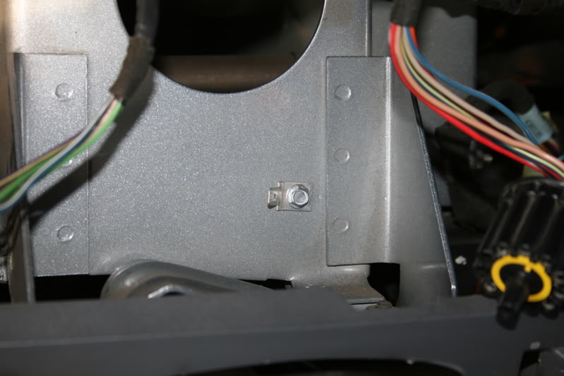
At this time before I went any farther I used compressed air and thoroughly cleaned out all of the dust and dirt from behind the dash, I then wiped everything down that I could reach with a rag soaked with Windex, kind a like spring cleaning behind your dash board.
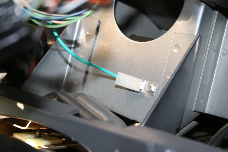
Then we will reinstall the instrument cluster in the reverse order but first connect the new ground wire onto the new grounding lug.
Now you can reinsert both of the connectors back into the circuit board and then swing it back up and into position.
On the right side there is a part of the housing that has to go behind the heater control so guide it in carefully and then secure it with the screws.
From here it is a simple matter of reverse the removal instructions and reassemble the dash.
Now we can start to reassemble the front of the cluster, using some Windex on a soft lint free towel carefully clean the both sides of the bezel and the clear plastic lens being careful as to not leave any lint on the surface.
And then after all of the gauges are in their respective locations you can now reinstall the bezel back onto the top of the faceplates and then replace the retaining screws.
Now we will take a look at the back of the printed circuit board and all of its connections.
I have no idea why it has a Ford lamp socket.
All of the connections to the gauges are passed through these staked in terminals, I have found most of my problems here since they were only pressed in and staked over.
This is how they are secured to the board; so simple a Caveman can do it.
So to cure this connection problem I cleaned all of the oxidation from around each terminal and the foil on the circuit board using a stainless brush.
And then I again removed the circuit board from the housing as to not damage the gauges of housing from heat and then after supporting the board I carefully soldered each connection using a small 20 watt soldering iron and a good quality .020 Rosin Core Solder.
Only apply enough heat to heat the connection and then touch the solder to the connection and NOT the tip of the iron.
This will draw the solder into the joint and create a good electrical connection, I then did this to all of the connections on the board.
This is how it should look when you are finished, I then cleaned it up using some flux remover.
Since all of the gauges in the cluster receive their ground from the same ground connection in the harness, I provided an additional grounding point for the circuit by installing an additional ground wire directly to the circuit board trace using a length of 16-gauge wire.
At the opposite end of this wire install a sturdy .250 Female Spade terminal to be easily disconnected when the cluster needs to be removed.
Now all of the internal modifications are done and we can reassemble the instrument cluster.
Carefully install the circuit board back onto the housing while aligning all of the protruding pins and then secure it using the removed screws.
I secured the ground wire to the back of the board using one of the screws to secure a small nylon wire clamp as a strain relief.
Now that the cluster is finished it is now time to prepare the dash so it can be reinstalled.
In the center of the dash behind where the cluster will go I installed a grounding lug into the sheet metal using a self-drilling sheet metal screw.
At this time before I went any farther I used compressed air and thoroughly cleaned out all of the dust and dirt from behind the dash, I then wiped everything down that I could reach with a rag soaked with Windex, kind a like spring cleaning behind your dash board.
Then we will reinstall the instrument cluster in the reverse order but first connect the new ground wire onto the new grounding lug.
Now you can reinsert both of the connectors back into the circuit board and then swing it back up and into position.
On the right side there is a part of the housing that has to go behind the heater control so guide it in carefully and then secure it with the screws.
From here it is a simple matter of reverse the removal instructions and reassemble the dash.
07-02-2008, 07:13 AM
#4
Administrator
Thread Starter
Part-4
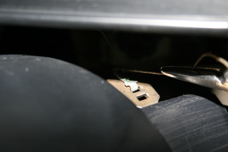
Now that the instrument panel is back in the dash and the plastic bezel is on you will need to reconnect the gear selector onto the shift column.
Make sure the steering column has been raised to its original position and the 2) 7/16” nuts have been tightened and then laying on the floorboard under the column using a pair of hemostats or needle nosed pliers simply get a hold of the tail if the string tied to the hook and slip it back into its proper slot in the bracket.
This picture is a view from the floor looking upwards.
You will still need to replace the lower fuse holder cover onto the dash and replace the 4 screws.
Replace all of the screws under the top of the bezel and the 1 screw above the radio and you should be about finished although there might be something I may have missed in writing by this memory after I had already done the work.
Now that all of the work to the instrument panel is complete I will now replace the incandesant lamps in my Autometer Gauges to the same LED’s.
How to install LED’s in the gauges.
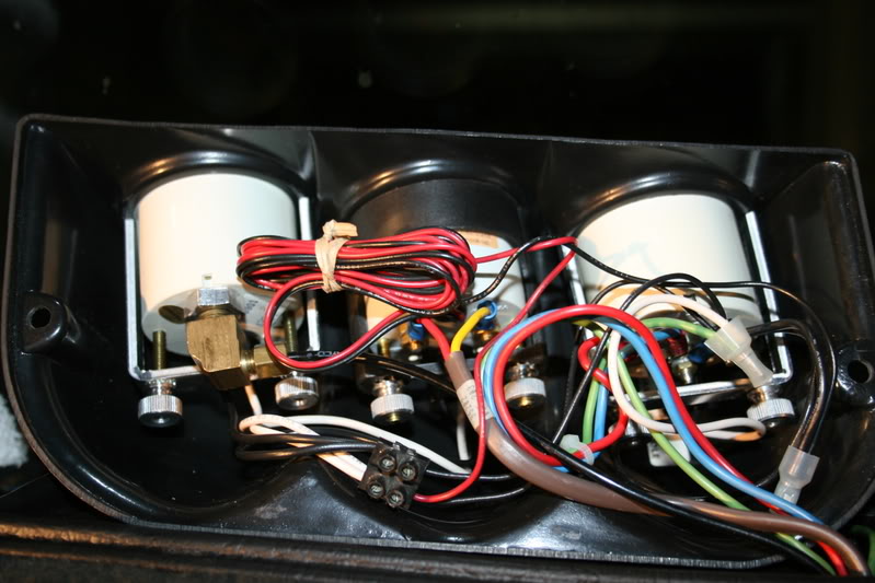
I have the 3-gauge Banks dash pod and to get to the gauges you have to remove the 2 screws holding the pod to the base.
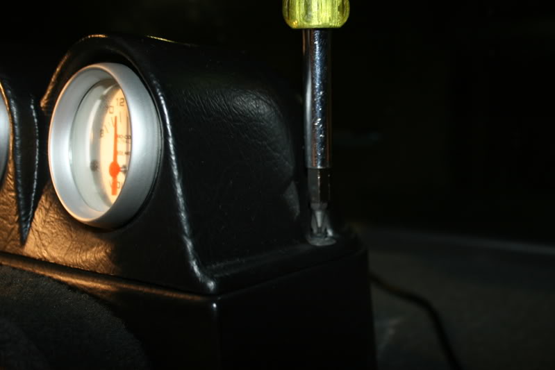
Now carefully turn it over to see how tight they are packed together.
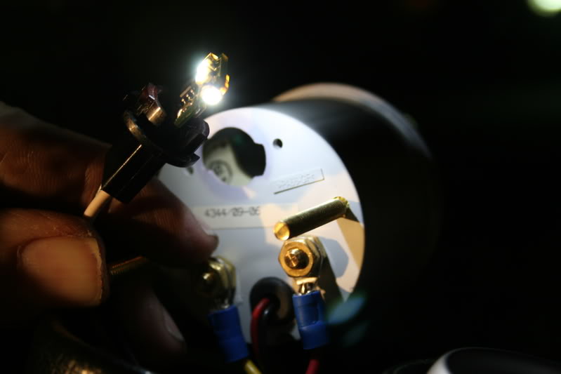
To remove the lamps the entire gauge will have to be loosened and slid out of the housing to gain access to the socket located on the top of the housing. So first the Boost line had to be disconnected.
Then you will remove the 2 knurled nuts and washers for each gauge you have.
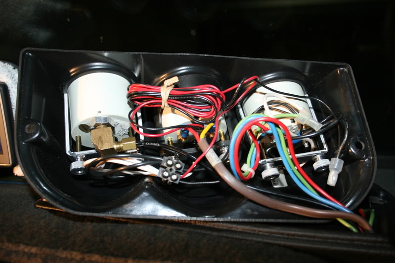
This is what the 6-die #194 module looks like; it will fit through the opening and replace the removed #194 lamp.
This is what upsets me about the plastic housings on the Autometer gauges; this was caused by the lamp that was shipped with the gauge
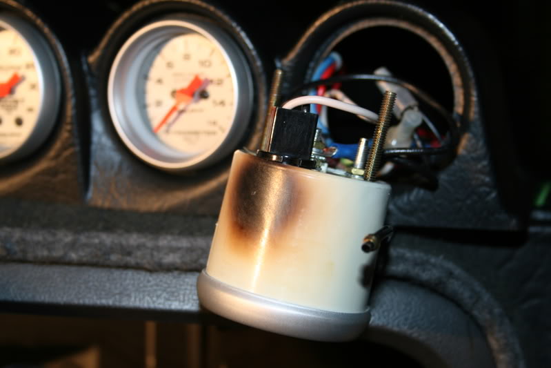
Repeat this step for each gauge you have and then tuck all of the wires back into the housing and connect anything else you may have removed.
Turn on the lights and make sure they all work, if they do not you might have to rotate the lamp 180* in the socket and reinsert them.
Now if everything is fine, go ahead and reinstall the pod back onto the base and re install the screws.
If you have gotten this far then you are all done.
Now for the best part of the story, you are going to see if all of the work was worth taking the time to do.
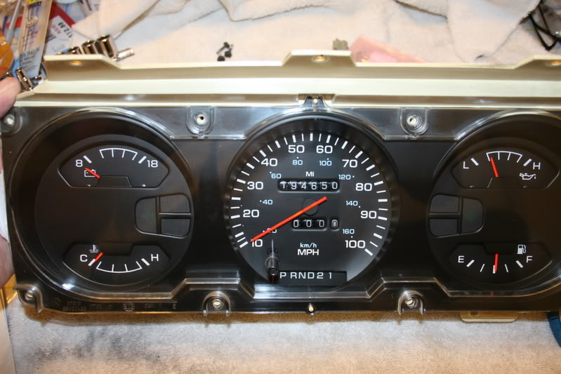
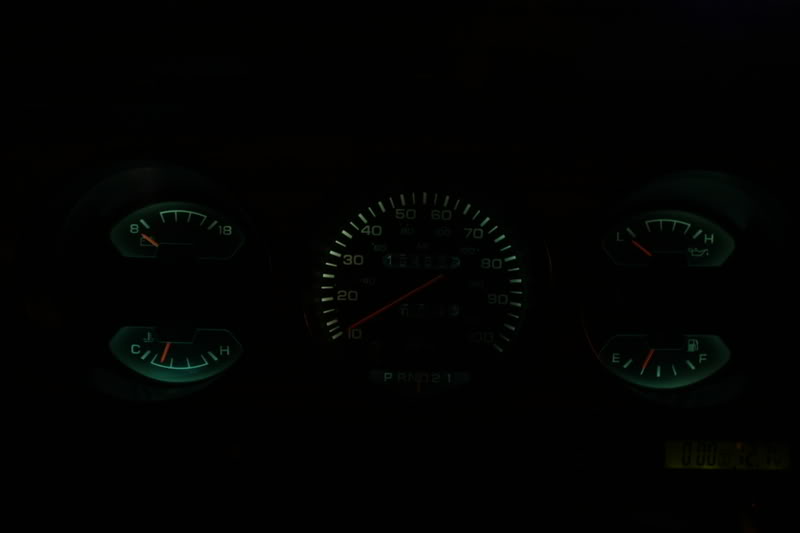
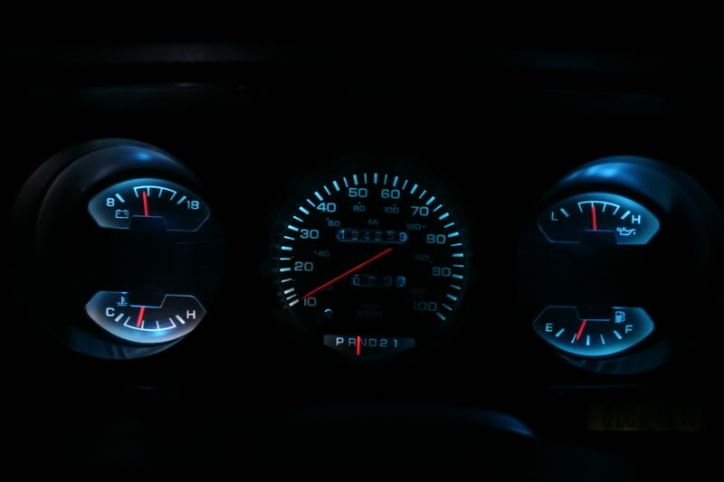
Here is what my stock instrument panel looked like.
The colors were a bit uneven and it was really difficult to read when it was dark, you had to really concentrate on where the needle was and yes all of the lamps were working.
Now this is what it looks like with the new LED’s AND the reflective foil I have installed inside the housing to help reflect the light off every part of the faceplate.
Yes it really is this bright and it is sill dimmable all the way down to OFF.
Notice how the gauge needles now fluoresce and are bright.
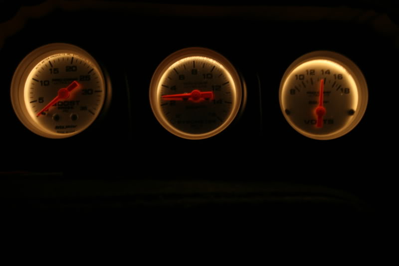
Here we are looking at the Autometer Gauges with the recommended incandescent lighting, although the gauge is silver, the light is still yellow
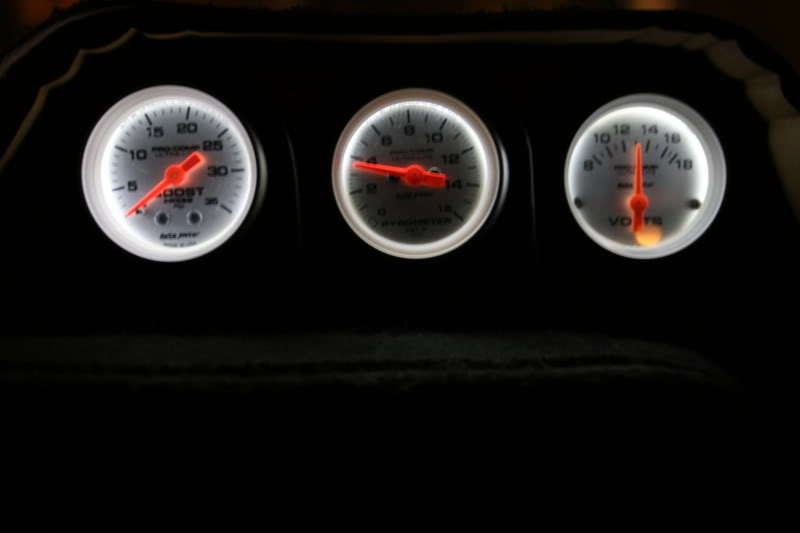
Here are the same gauges except now they have a bright bluish white light and are a lot easier to read and also notice how bright the pointers are.
Of all of the modifications I have done to my truck lately, this one has really made the truck a lot less stressful to drive because I like to be able to see all of my insturmation without straining to see them.
Note: throughout this story, Needle and Pointer were used interchangeably and is the same item.
List of Materials:
2’) Aluminum Foil Tape used in HVAC (Home Depot has it)
* ˝” instrument panel sockets you may require up to 6 of them Motor Mite #85835 (auto Zone)
I purchased the following LED’s from superbrightleds.com
The customer service department was very nice and helpful.
6) WLED-WHP6 6 Pure White High Output LED’s Instrument cluster illumination.
2) WLED-G4 4 LED Green Turn Signal Indicators
1) WLED-B4 4 LED Blue High Beam Indicator
Short length of 16-gauge wire for supplemental ground.
.250 Female Spade terminal
.250 Male Spade grounding lug.
Cleaning supplies, Windex, soft lint free cloth.
Fluorescent Red paint and brush.
Soldering iron and rosin core solder.
Note, I have been driving my truck for about 2 weeks now and the gauges in the instrument panel all seem to be rock solid, no wandering.
As always if there is any questions you may have please feel free to ask.
Thank you for allowing me to show you what I am doing to my truck.
Jim
Now that the instrument panel is back in the dash and the plastic bezel is on you will need to reconnect the gear selector onto the shift column.
Make sure the steering column has been raised to its original position and the 2) 7/16” nuts have been tightened and then laying on the floorboard under the column using a pair of hemostats or needle nosed pliers simply get a hold of the tail if the string tied to the hook and slip it back into its proper slot in the bracket.
This picture is a view from the floor looking upwards.
You will still need to replace the lower fuse holder cover onto the dash and replace the 4 screws.
Replace all of the screws under the top of the bezel and the 1 screw above the radio and you should be about finished although there might be something I may have missed in writing by this memory after I had already done the work.
Now that all of the work to the instrument panel is complete I will now replace the incandesant lamps in my Autometer Gauges to the same LED’s.
How to install LED’s in the gauges.
I have the 3-gauge Banks dash pod and to get to the gauges you have to remove the 2 screws holding the pod to the base.
Now carefully turn it over to see how tight they are packed together.
To remove the lamps the entire gauge will have to be loosened and slid out of the housing to gain access to the socket located on the top of the housing. So first the Boost line had to be disconnected.
Then you will remove the 2 knurled nuts and washers for each gauge you have.
This is what the 6-die #194 module looks like; it will fit through the opening and replace the removed #194 lamp.
This is what upsets me about the plastic housings on the Autometer gauges; this was caused by the lamp that was shipped with the gauge
Repeat this step for each gauge you have and then tuck all of the wires back into the housing and connect anything else you may have removed.
Turn on the lights and make sure they all work, if they do not you might have to rotate the lamp 180* in the socket and reinsert them.
Now if everything is fine, go ahead and reinstall the pod back onto the base and re install the screws.
If you have gotten this far then you are all done.
Now for the best part of the story, you are going to see if all of the work was worth taking the time to do.
Here is what my stock instrument panel looked like.
The colors were a bit uneven and it was really difficult to read when it was dark, you had to really concentrate on where the needle was and yes all of the lamps were working.
Now this is what it looks like with the new LED’s AND the reflective foil I have installed inside the housing to help reflect the light off every part of the faceplate.
Yes it really is this bright and it is sill dimmable all the way down to OFF.
Notice how the gauge needles now fluoresce and are bright.
Here we are looking at the Autometer Gauges with the recommended incandescent lighting, although the gauge is silver, the light is still yellow
Here are the same gauges except now they have a bright bluish white light and are a lot easier to read and also notice how bright the pointers are.
Of all of the modifications I have done to my truck lately, this one has really made the truck a lot less stressful to drive because I like to be able to see all of my insturmation without straining to see them.
Note: throughout this story, Needle and Pointer were used interchangeably and is the same item.
List of Materials:
2’) Aluminum Foil Tape used in HVAC (Home Depot has it)
* ˝” instrument panel sockets you may require up to 6 of them Motor Mite #85835 (auto Zone)
I purchased the following LED’s from superbrightleds.com
The customer service department was very nice and helpful.
6) WLED-WHP6 6 Pure White High Output LED’s Instrument cluster illumination.
2) WLED-G4 4 LED Green Turn Signal Indicators
1) WLED-B4 4 LED Blue High Beam Indicator
Short length of 16-gauge wire for supplemental ground.
.250 Female Spade terminal
.250 Male Spade grounding lug.
Cleaning supplies, Windex, soft lint free cloth.
Fluorescent Red paint and brush.
Soldering iron and rosin core solder.
Note, I have been driving my truck for about 2 weeks now and the gauges in the instrument panel all seem to be rock solid, no wandering.
As always if there is any questions you may have please feel free to ask.
Thank you for allowing me to show you what I am doing to my truck.
Jim
The following 2 users liked this post by Jim Lane:
Federic (01-30-2021),
Werner1111 (05-23-2017)


Trending Topics


 07-03-2008, 02:46 PM
#13
Registered User

GREAT JOB AGAIN.
You mentioned something about some of the trucks might have one-piece bulbs/sockets and something else would need be bought to remedy this.
Do you have pictures of both what we might run into and what we would need to replace it with ??
Thanks.
Also, I will add this bit of experience that we gained when working on the son's truck.
His truck had previously been employed at a large feed and fertilize distributor; and, I don't think it had ever seen a wash-bucket nor had the windows ever been rolled up during dust storms.
The clear plastic over the gauges was so scratched up that, even after a good cleaning, I still could hardly see through it.
We worked it over with Meguiar's PlastX Clear Plastic Cleaner and Polish.
I was amazed; it now looks better than new; that stuff is every bit as good as they claim it is.
Besides polishing the plastic, re-painting the needles in the same manner that you used really made the instrument panel look nice.


