Project 6.1 Cummins

 03-16-2015, 01:46 PM
#62
Registered User

Join Date: Sep 2014
Posts: 138
Likes: 0
Received 0 Likes
on
0 Posts
Well if they were 220,000 psi:
14/25.4=.55118 diameter converted to inches
Now square that: .55118x.55118=.3038
Now multiply .3038x.7854=.2386 inches square( cross sectional area of the bolt)
Now multiply .2386x220,000=52,493.09 lbs breaking strength
Now multiply by 23 head bolts=1,207,341.29 lbs
Granted this is all theoretical and my math my be off aswell as my understanding of what tensile strength is so... Take it for what it's worth.
03-16-2015, 07:52 PM
#63
Registered User
Thread Starter

That is accurate for how much they can hold but it is not exactly what they are torqued to. The clamping force will be less than the tensile strength. This is a great calculator for calculating clamping force.
http://www.futek.com/boltcalc.aspx
http://www.futek.com/boltcalc.aspx
03-18-2015, 01:59 PM
#66
Registered User
Thread Starter
My plan for the intake plenum is obviously a piece of billet. But what I need to do is incorporate a fuel filter base. This should also help keep fuel warm on cold days. Im going to machine an area like the first gens have where the fuel filter will screw on. Also I would be able to use stock fuel lines and stock fuel filter first gen style.
03-18-2015, 02:25 PM
#67
Registered User
truthfully I would run something different if given the choice. The first gen fuel filter assy has very poor flow through it.
I run a late second gen fuel filter setup. I like it
I run a late second gen fuel filter setup. I like it
03-18-2015, 03:46 PM
#68
Registered User
Thread Starter
I see what you mean however for what I need its perfect. very inexpensive as well as readily available. I always keep a spare in the glove box.
03-26-2015, 09:05 PM
#69
Registered User
Thread Starter
Back to the top I guess. I have been waiting verypatiently for my 6.7 Crank to arrive as well as getting my block machined. So mean while I finished o-ringing the head with .043'' wire with .010-.011'' protrusion. This is the sample cut and wire fitment.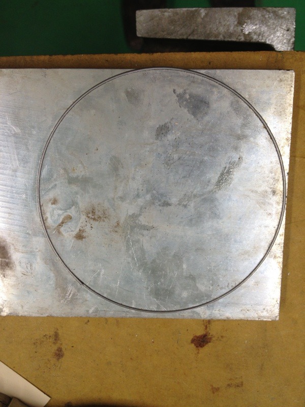
This is the head all done.
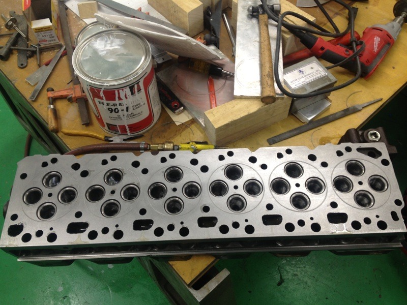
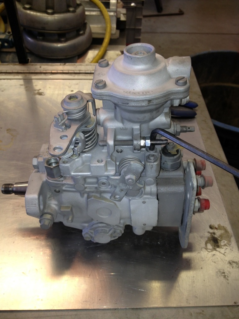
Also while I was waiting so patiently I started the rebuild of the Bluebird bus VE pump with stock 3.5mm cam plate.
Sand blasted and ready for taredown
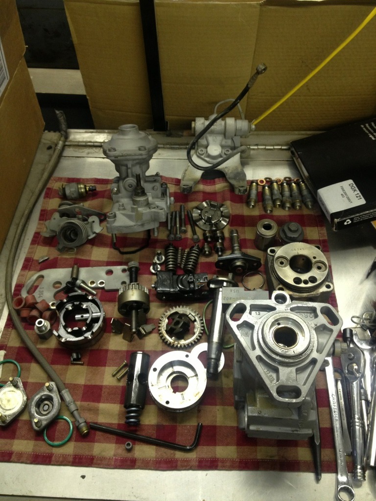
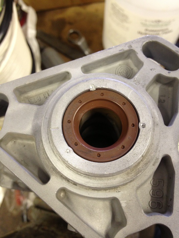
I never understood why people loctite their VE drive shaft seals... This is way easier and should hold well past what ever the pump will ever see.
This is the head all done.
Also while I was waiting so patiently I started the rebuild of the Bluebird bus VE pump with stock 3.5mm cam plate.
Sand blasted and ready for taredown
I never understood why people loctite their VE drive shaft seals... This is way easier and should hold well past what ever the pump will ever see.
03-26-2015, 09:18 PM
#70
Registered User
Thread Starter
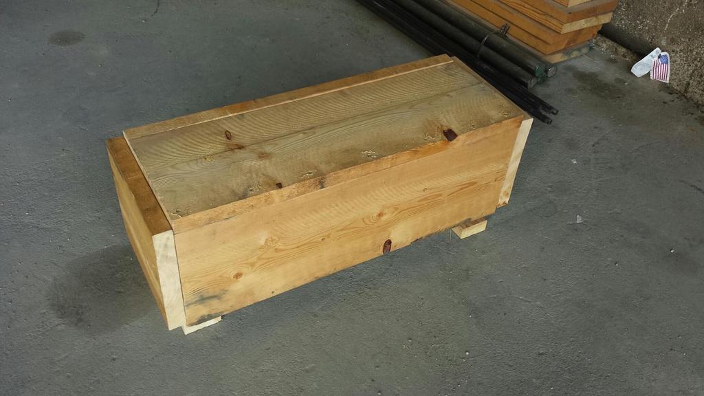
I was able to find a 6.7 crank the gentleman I bought it from was very nice and did a wonderful job of packaging the crankshaft.
removing the straight cut crankshaft gear to install the helical cut crankshaft gear.
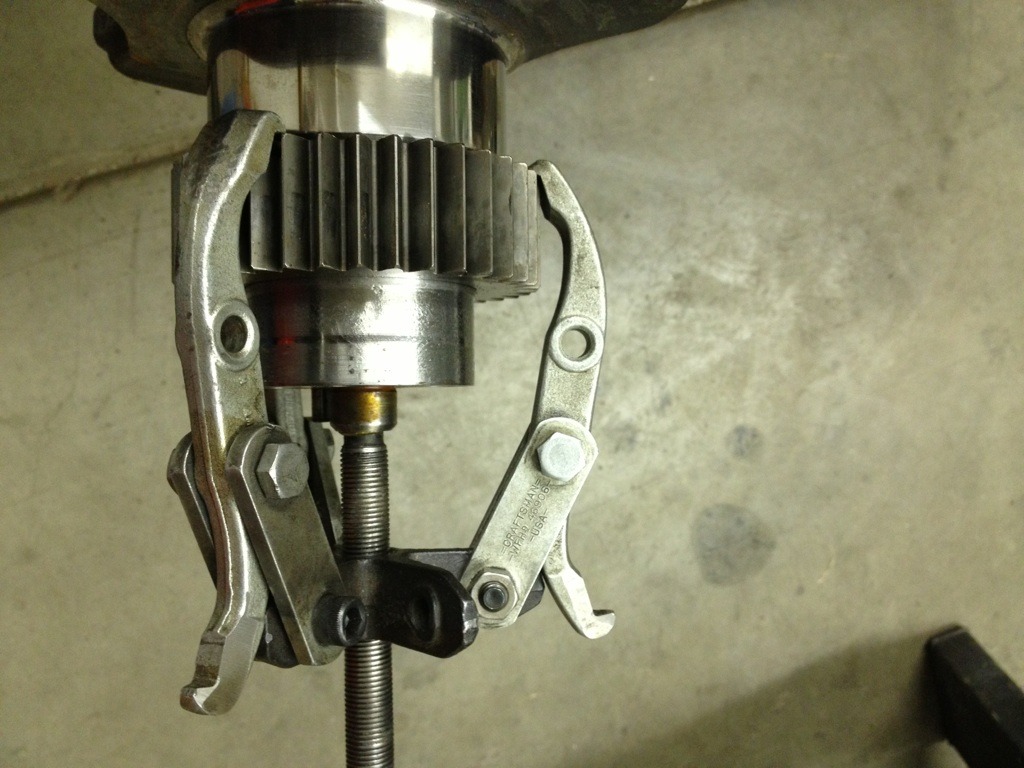
At this point the block was finished up and installed onto the engine stand. I will start assembly tomorrow.
removing the straight cut crankshaft gear to install the helical cut crankshaft gear.
At this point the block was finished up and installed onto the engine stand. I will start assembly tomorrow.
03-27-2015, 02:31 AM
#71
Registered User
ohhhh I like pictures.
I hear the 6.7 crank comes REAL close to either the cam or rods... can't remember which...
Head looks good. I'd love to try a 24v head.
I hear the 6.7 crank comes REAL close to either the cam or rods... can't remember which...
Head looks good. I'd love to try a 24v head.
03-27-2015, 09:32 AM
#72
Registered User
Thread Starter
Ive heard that too. If i listened to all those people who have "heard" i wouldt be attemting this project lol. I will quickly find out and put rumors to rest. This is the real deal. If there's a will, theres a way. Ill get it in there one way or another. 👍
03-28-2015, 10:31 PM
#73
Registered User
Thread Starter
Wow the rod caps do come close to the camshaft. I dont know if it will clear the fuel pump lobe when I install the 12v camshaft. I might have to put an electric pump on.
03-29-2015, 10:21 AM
#74
Registered User
 Isn't that the truth?
03-29-2015, 09:04 PM
Isn't that the truth?
03-29-2015, 09:04 PM
#75
Registered User
IIRC he said he shaved a little off the cap? to make sure it wouldn't contact anything and then had them balanced.
My memory sucks and I'm really not sure of the details.
What are your plans to remedy the extra travel the 6.7 crank provides? are you just going to run a thicker HG or will you shave the pistons?