Crank position sensor issues
 01-23-2015, 12:43 PM
#1
Crank position sensor issues
On my 93 Cummins I have a problem to where my tach, alternator, and wait to start functions do not work, this all only happen when its cold. Did the external regulator and push button for intake heaters. Lately I have be wanting to get it back to normal, mostly on the wait to start and tach.
I have be doing some look on the web and have found that it could be something with the CPS. I looked up the plug on the front of the engine found that:
The black wire with blue tracer is sensor return (AKA ground)
The tan wire with yellow tracer is 8volt supply
And the grey wire with black tracer is the signal wire.
With this info I went to the truck and turned the key to run and then went to the plug on the front of the engine, and un plugged it. on the side of the plug not connected to the CPS, in the
Tan and yellow wire I had the 8volts. Good
Grey and black wire I had about 8volts also. Wrong I think.
Didn't have an ohm meter to check the return wire.
I question is should I be getting power in the signal wire. I don't think so.
If I shouldn't be getting power here what might be the source on it, and could this be the problem causeing the early mentioned problems.
Thanks for any input.
 01-23-2015, 05:06 PM
#2
Registered User
On my 93 Cummins I have a problem to where my tach, alternator, and wait to start functions do not work, this all only happen when its cold. Did the external regulator and push button for intake heaters. Lately I have be wanting to get it back to normal, mostly on the wait to start and tach.
I have be doing some look on the web and have found that it could be something with the CPS. I looked up the plug on the front of the engine found that:
The black wire with blue tracer is sensor return (AKA ground)
The tan wire with yellow tracer is 8volt supply
And the grey wire with black tracer is the signal wire.
With this info I went to the truck and turned the key to run and then went to the plug on the front of the engine, and un plugged it. on the side of the plug not connected to the CPS, in the
Tan and yellow wire I had the 8volts. Good
Grey and black wire I had about 8volts also. Wrong I think.
Didn't have an ohm meter to check the return wire.
I question is should I be getting power in the signal wire. I don't think so.
If I shouldn't be getting power here what might be the source on it, and could this be the problem causeing the early mentioned problems.
Thanks for any input.
I have be doing some look on the web and have found that it could be something with the CPS. I looked up the plug on the front of the engine found that:
The black wire with blue tracer is sensor return (AKA ground)
The tan wire with yellow tracer is 8volt supply
And the grey wire with black tracer is the signal wire.
With this info I went to the truck and turned the key to run and then went to the plug on the front of the engine, and un plugged it. on the side of the plug not connected to the CPS, in the
Tan and yellow wire I had the 8volts. Good
Grey and black wire I had about 8volts also. Wrong I think.
Didn't have an ohm meter to check the return wire.
I question is should I be getting power in the signal wire. I don't think so.
If I shouldn't be getting power here what might be the source on it, and could this be the problem causeing the early mentioned problems.
Thanks for any input.
I'd start by checking all the power and grounds to the PCM. Then check to see if it's alive. Pull codes.....should be at least a 55, but also should be codes on alternator field and maybe grid heater circuits. That's to see if the PCM is running.
Signal on the CPS when you get there should toggle between 5V and near ground. Check it with the CPS connected. There might be a high value pull up resistor in the PCM that would give you an errant reading.
01-23-2015, 06:34 PM
#3
when it is cold and having problems it appears that the pcm is dead no codes. As it warms up the auto shutdown relay, well start to click on and off and the tach will bounce around with it once is back to operating correctly the intake heaters will cycle, the tach will work and before the external regulator the alternator would work, I also get the alternator class and code 55.
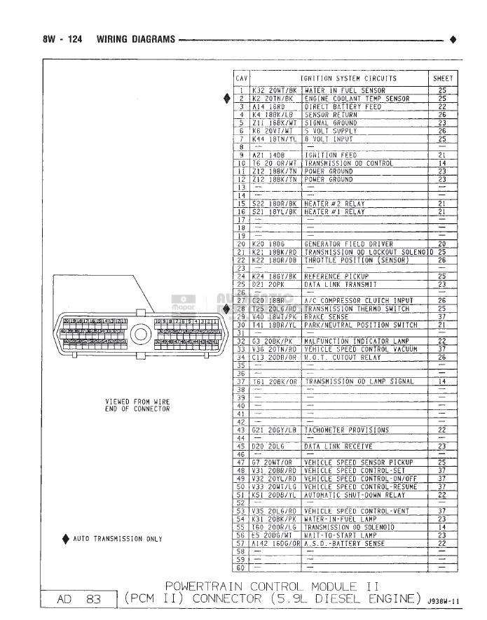
So I guess I need to check pcm power and ground. Anyone have a diagram so I know where to look for power and ground.
Thanks
So I guess I need to check pcm power and ground. Anyone have a diagram so I know where to look for power and ground.
Thanks
 01-24-2015, 08:39 AM
#7
Registered User

Back probe it first. If all looks good, then unplug the connector, check it for clean, and reconnect. (operation called re-seating the connector)
On the grounds, you are looking for extremely low voltage compared to negative battery terminal. Second check would be battery disconnected ohms to negative battery terminal. (not the battery)
Check all power and signal grounds, and the several 12v inputs. (direct, key, ASD)
Trending Topics
01-24-2015, 11:59 AM
#8
So checked things today, what am I looking for at the ASD relay pin 51 and ASD battery sence pin 57. I have nothing at either one, not sure if I should or not. where should head next. Thanks
01-24-2015, 12:07 PM
#9
Registered User

Some where I saw a post that basically said they built a 5 V, external power supply and fed it in to the PCM to fix an intermittent problem. I have looked but cant find it. Seems plausible as it seems that most electronic operate on 5 V.
Mike
Mike
01-24-2015, 04:23 PM
#11
Registered User
You may be right with your first hunch, ie CPS functionally equivalent to a penny. However, on average proper diagnostics is the fastest and least expensive path to repair.
01-24-2015, 04:30 PM
#12
Needs CPS to do that. Now check the CPS while connected. It will toggle slowly while you manually turn the engine past the notch.
You may be right with your first hunch, ie CPS functionally equivalent to a penny. However, on average proper diagnostics is the fastest and least expensive path to repair.
You may be right with your first hunch, ie CPS functionally equivalent to a penny. However, on average proper diagnostics is the fastest and least expensive path to repair.
Thanks
01-24-2015, 09:54 PM
#13
Registered User
If it's at 8V to start with, the CPS is probably hosed.

Thread
Thread Starter
Forum
Replies
Last Post
kingofdodge7131
24 Valve Engine and Drivetrain
3
05-24-2004 01:09 PM