How the Speedometer Sending Assembly works
 03-24-2008, 01:29 PM
#1
DTR's Night Watchman & Poet Laureate
Thread Starter
How the Speedometer Sending Assembly works
How the VSS assembly works and goes together.( pictures will be added once uploaded and aproved)
Since this seems to be a common question, and troubleshooting issue, I thought it might be helpful to explain what parts make up the speedometer sending assembly used on our trucks. There are slight variations from year to year, but basically this is how the Electronic Variable Speed Sensor Assembly works.
We�ll start by locating it. On 4WD trucks, the VSS is located on the transfer case output shaft housing on the drivers side. On 2wd trucks, it�s located on the driver�s side of the transmission output shaft housing directly above the transmission cross member.
Ok, how it works�
In both cases, there is a plastic worm gear that rides on the shaft inside the transmission/transfer case housing. It is held in place by two long bushings and can sometimes be replaced by removing the output yoke and seals and sliding it out. It is a dealer only part:

The Pinion Drive gear rides on the worm gear and powers the VSS. The Pinion Drive Gear (PDG) is a plastic gear with a hollow shaft, which is squared inside. It determines the gear ratio of the speedometer by the number of teeth on the gear. I.e. most stock trucks came with a 32-tooth gear. Various gear counts can be purchased to adapt the speedo to differing rear-end gear ratios or tire sizes. These gears are color coded to indicate the tooth count. The PDG is a dealer only part:

Common Problems with both the Worm Gear and PDG are broken or worn teeth or a rounded out shaft on the PDG.
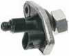
The Pinion Drive Gear is supported by the Gear housing, which is the piece that you actually see when looking at the transmission or transfer case.
It slides into the transmission housing and is held in place by a �U� shaped retainer and one bolt. It seals by a large thin o-ring which can be easily replaced should it develop a leak. The threaded section is what the Gear Ratio Reducer attaches to.

Next in line is the Gear Ratio Reducer (sometimes referred to as the 90* gear box). This is simply a small rectangular box, which houses small plastic gears. Its function is to increase the speed of the VSS shaft; so that it will produce a strong enough voltage to power the speedometer and to keep it operating correctly at all speeds. Some models did not utilize a separate Gear Reducer. The Gear Reducer is a dealer only part. Common problems with the Gear reducer are broken gears and gear shafts internally and rounding off of the square shaft that slides into the Pinion Drive Gear.
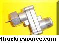
Finally, there is the VSS or Variable Speed Sensor itself. This is the final output unit of the assembly and is what actually send an electrical signal to the ECM and then to the Speedometer. Common problems with it include dirty or loose connections, a tendency to fall off completely, rounding off of the drive shaft and cracking at the threaded coupler with the Gear Reducer. The VSS is available through NAPA and other aftermarket sources.
The VSS is the most common part to fail in the speedometer assembly.
Now, to confuse matters, starting in mid 93 production, a VSS was used that incorporated the Gear Housing , reducer and VSS into a single unit. However the drive portion of the assembly did not change, and the basic function remains the same.
I hope this helps anyone with questions about how the Speedometer Sending Assembly works and what parts comprise it.
Since this seems to be a common question, and troubleshooting issue, I thought it might be helpful to explain what parts make up the speedometer sending assembly used on our trucks. There are slight variations from year to year, but basically this is how the Electronic Variable Speed Sensor Assembly works.
We�ll start by locating it. On 4WD trucks, the VSS is located on the transfer case output shaft housing on the drivers side. On 2wd trucks, it�s located on the driver�s side of the transmission output shaft housing directly above the transmission cross member.
Ok, how it works�
In both cases, there is a plastic worm gear that rides on the shaft inside the transmission/transfer case housing. It is held in place by two long bushings and can sometimes be replaced by removing the output yoke and seals and sliding it out. It is a dealer only part:
The Pinion Drive gear rides on the worm gear and powers the VSS. The Pinion Drive Gear (PDG) is a plastic gear with a hollow shaft, which is squared inside. It determines the gear ratio of the speedometer by the number of teeth on the gear. I.e. most stock trucks came with a 32-tooth gear. Various gear counts can be purchased to adapt the speedo to differing rear-end gear ratios or tire sizes. These gears are color coded to indicate the tooth count. The PDG is a dealer only part:
Common Problems with both the Worm Gear and PDG are broken or worn teeth or a rounded out shaft on the PDG.
The Pinion Drive Gear is supported by the Gear housing, which is the piece that you actually see when looking at the transmission or transfer case.
It slides into the transmission housing and is held in place by a �U� shaped retainer and one bolt. It seals by a large thin o-ring which can be easily replaced should it develop a leak. The threaded section is what the Gear Ratio Reducer attaches to.
Next in line is the Gear Ratio Reducer (sometimes referred to as the 90* gear box). This is simply a small rectangular box, which houses small plastic gears. Its function is to increase the speed of the VSS shaft; so that it will produce a strong enough voltage to power the speedometer and to keep it operating correctly at all speeds. Some models did not utilize a separate Gear Reducer. The Gear Reducer is a dealer only part. Common problems with the Gear reducer are broken gears and gear shafts internally and rounding off of the square shaft that slides into the Pinion Drive Gear.
Finally, there is the VSS or Variable Speed Sensor itself. This is the final output unit of the assembly and is what actually send an electrical signal to the ECM and then to the Speedometer. Common problems with it include dirty or loose connections, a tendency to fall off completely, rounding off of the drive shaft and cracking at the threaded coupler with the Gear Reducer. The VSS is available through NAPA and other aftermarket sources.
The VSS is the most common part to fail in the speedometer assembly.
Now, to confuse matters, starting in mid 93 production, a VSS was used that incorporated the Gear Housing , reducer and VSS into a single unit. However the drive portion of the assembly did not change, and the basic function remains the same.
I hope this helps anyone with questions about how the Speedometer Sending Assembly works and what parts comprise it.

The following users liked this post:
Gray92 (12-27-2018)
 03-25-2008, 09:40 PM
#3
DTR's Night Watchman & Poet Laureate
Thread Starter
AS an after-thought, for those with pre-89 trucks, they used a cable drive, the PDG, and internal parts are the same, but a cable hooks up were the VSS is on later model years...
03-26-2008, 12:42 AM
#4
Registered User

Good much-needed article.
I have been told that the adapter spins the cable in the opposite direction on the cable-drive speedometers; is this fact ??
I do know for a fact that the 1989 adapter reverses the direction of the shaft.
03-26-2008, 05:41 AM
#5
Administrator

How the VSS assembly works and goes together.( pictures will be added once uploaded and aproved)
Since this seems to be a common question, and troubleshooting issue, I thought it might be helpful to explain what parts make up the speedometer sending assembly used on our trucks. There are slight variations from year to year, but basically this is how the Electronic Variable Speed Sensor Assembly works.
We�ll start by locating it. On 4WD trucks, the VSS is located on the transfer case output shaft housing on the drivers side. On 2wd trucks, it�s located on the driver�s side of the transmission output shaft housing directly above the transmission cross member.
Ok, how it works�
In both cases, there is a plastic worm gear that rides on the shaft inside the transmission/transfer case housing. It is held in place by two long bushings and can sometimes be replaced by removing the output yoke and seals and sliding it out. It is a dealer only part:
The Pinion Drive gear rides on the worm gear and powers the VSS. The Pinion Drive Gear (PDG) is a plastic gear with a hollow shaft, which is squared inside. It determines the gear ratio of the speedometer by the number of teeth on the gear. I.e. most stock trucks came with a 32-tooth gear. Various gear counts can be purchased to adapt the speedo to differing rear-end gear ratios or tire sizes. These gears are color coded to indicate the tooth count. The PDG is a dealer only part:
Common Problems with both the Worm Gear and PDG are broken or worn teeth or a rounded out shaft on the PDG.
The Pinion Drive Gear is supported by the Gear housing, which is the piece that you actually see when looking at the transmission or transfer case.
It slides into the transmission housing and is held in place by a �U� shaped retainer and one bolt. It seals by a large thin o-ring which can be easily replaced should it develop a leak. The threaded section is what the Gear Ratio Reducer attaches to.
Next in line is the Gear Ratio Reducer (sometimes referred to as the 90* gear box). This is simply a small rectangular box, which houses small plastic gears. Its function is to increase the speed of the VSS shaft; so that it will produce a strong enough voltage to power the speedometer and to keep it operating correctly at all speeds. Some models did not utilize a separate Gear Reducer. The Gear Reducer is a dealer only part. Common problems with the Gear reducer are broken gears and gear shafts internally and rounding off of the square shaft that slides into the Pinion Drive Gear.
Finally, there is the VSS or Variable Speed Sensor itself. This is the final output unit of the assembly and is what actually send an electrical signal to the ECM and then to the Speedometer. Common problems with it include dirty or loose connections, a tendency to fall off completely, rounding off of the drive shaft and cracking at the threaded coupler with the Gear Reducer. The VSS is available through NAPA and other aftermarket sources.
The VSS is the most common part to fail in the speedometer assembly.
Now, to confuse matters, starting in mid 93 production, a VSS was used that incorporated the Gear Housing , reducer and VSS into a single unit. However the drive portion of the assembly did not change, and the basic function remains the same.
I hope this helps anyone with questions about how the Speedometer Sending Assembly works and what parts comprise it.
I have found that most good Speedometer and Tachometer Repair Shops can build you a Ratio Adapter on the spot, and they have an assortment of the drive pins.
Check around bigger Truck Stops and they are usually around.
Nice write-up.
Jim
03-26-2008, 07:46 AM
#7
DTR's Night Watchman & Poet Laureate
Thread Starter
Not sure on that one, I only know about the pre-89 trucks from the fact that the VSS is listed as for 89& up trucks.....
Trending Topics
 04-17-2008, 12:35 AM
#9
Registered User
04-17-2008, 01:01 AM
#10
DTR's Night Watchman & Poet Laureate
Thread Starter
 05-07-2008, 11:56 AM
#12
Registered User

Join Date: Apr 2007
Location: Central Mi
Posts: 666
Likes: 0
Received 0 Likes
on
0 Posts
chrisreyn,
Just got thru ordering parts for a rebuild on my trans and all the parts you referred to as being dealer only were offered...
The site is PATC down in La I believe their website is
http://www.transmissioncenter.net/dodge.htm
Down yowards the bottom of a VERY LOOOooong page...
Prices are reasonable too...
05-07-2008, 01:22 PM
#13
DTR's Night Watchman & Poet Laureate
Thread Starter
Its someone with no life.......
Cool unix, I had only checked with places like NAPA and such.. good to know!
chrisreyn,
Just got thru ordering parts for a rebuild on my trans and all the parts you referred to as being dealer only were offered...
The site is PATC down in La I believe their website is
http://www.transmissioncenter.net/dodge.htm
Down yowards the bottom of a VERY LOOOooong page...
Prices are reasonable too...
Just got thru ordering parts for a rebuild on my trans and all the parts you referred to as being dealer only were offered...
The site is PATC down in La I believe their website is
http://www.transmissioncenter.net/dodge.htm
Down yowards the bottom of a VERY LOOOooong page...
Prices are reasonable too...
04-20-2009, 08:03 PM
#14
Registered User
Ratio Drive
I don't suppose any are still around, but mine's shot and I've been running my VSS sensor directly on my speedo output shaft on the Getrag. Runs about 33% faster than I'm going and the cruise control doesn't work (dunno why that is) , .... my dealer assured me they're extinct, but that tip about speed shops and performance shops building them has me hoping again.
04-21-2009, 10:30 AM
#15
Registered User

On my 91 and 92(and probably my 93, haven't checked yet) NP205 4x4 trucks, the pinion drive gear and gear housing are one assembly, metal gear, and thread into a threaded hole in the NP205. The drive gear and housing off of a spare 2wd parts getrag I have look like the ones you posted. My questions are, did the worm gear color/# of teeth stay the same with 3.54 and 4.10 gears and they just changed the pinion drive gear, or did both change? Also, did the tooth counts stay the same over the years for each? Are all angle drive adapters and speed sensors the same, even between 2wd and 4x4, and all ratios? In my picture below, the parts from a 91 NP205 setup are on the left, the pinion drive gear and housing out of my 2wd getrag and the hold down clamp are on the right.

