Replace Your 12v CTD Head-Gasket
 03-21-2009, 12:26 AM
#1
1st Generation Admin
Thread Starter
Folks, this is another attempt to repay the vast knowledge afforded me by the DTR community.
Today, we're gonna replace the head-gasket on my 1993 Dodge/Cummins 5.9ltr intercooled 12 valve engine with an automatic transmission. Perhaps you're making general repairs such as an antifreeze leak. Such is the case with me, or at least it started that way. We won't be getting into performance modification stuff, just the basic service/replacement of the stock/OEM gasket.
On that note, be aware that my images used in this thread cover a number of years, involving a number of different projects. You may see the valve-covers off well before being instructed to remove them for example. Work with me.
As always ~ SAFETY FIRST!!
- Disconnect the Negative cable of your battery system.
- Chock the wheels and set the parking brake.
- Have a known good fire extinguisher close by.
- Have good lighting.
- Have a clean and orderly work area.
- Always exercise good working practice with your tools.
- Use safety goggles, gloves, masks, etc where appropriate.
- RTFM!
- I always clean the area I plan on working in the night before. Use the engine cleaner of your choice (follow the directions) and forcefully flush everything with a strong garden hose.
Finally know that I'm using the Chrysler Corporation 1993 Service Manual for the D&W 150-350 Ramcharger RWD truck as my guide in ensuring I hit all the bases. This thread is not to be considered "The Authoritive How-To" regarding working on your mess.
OK, fine . . . . .
- Spray the turbocharger and exhaust manifold bolts with your favorite penetrating oil. While you're at it, hit the turbochargers oil feed-line fittings where they enter the turbocharger.
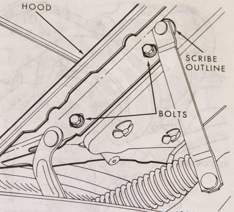
- With the help of friends, remove the hood of the truck. Careful of the windshield! You might scribe around the hinge mounts so you can put things back together right. I just used the factory paint marks as reference.
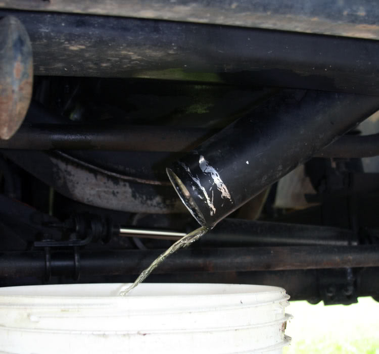
- Drain the engine coolant. Always catch and contain the mess as it's poison never mind expensive. I end up using the turbocharger to intercooler pipe to get from the radiator's petcock to my bucket. I strain it if needed and put it right back in when complete.
- Drain the engine oil. I've found that most all restaurants use frying oil that comes as a five gallon plastic jug in a cardboard box. They won't mind you getting the empty containers out of their way. Makes it easy to take it to the local Auto-Zone or such that have the used oil recycling drums. It's free.
- If your truck's non-intercooled, this ought to be a good time to remove the charge-air cross-over pipe. Stuff a clean towel into the turbocharger's outlet, and the charge-air intake's feed-horn.
-Disconnect and remove the top radiator hose as well as the two cab heater hoses. Be careful tugging on the cab heat water valve and heater core connections. I've found it helpful to pinch the rubber hose here and there where it engages the connectors so as to first break the rubber/metal bond. Then pull them free.
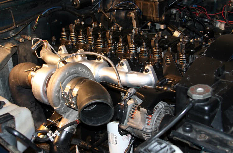
- Remove the turbocharger assembly. The intake and exhaust plumbing first, then the oil feed-line. BE SURE to use a back-up wrench on the feed-line fittings. Be prepared for the actual oil tube to stick to it's fitting. You don't want it to turn with the fitting as you may wring the tube off so be patient with it. Follow that with disconnecting the oil drain line. As you remove the turbo, you'll find a single metal gasket between the turbo and exhaust manifold. I temporarily put the gasket, nuts and washers back on the manifold studs so I won't loose them.
With removal of the turbo, be sure to plug all the oil openings so as to ensure no trash gets in there. If you think you might not be able to stay off the oil supply tube where it connects to the engine oil filter assembly, go ahead and remove it using the same methods and precautions.
- Remove the exhaust manifold. I usually leave a bolt loose at each end till all the others are removed. Here again, to help keep trash out of things, stuff some paper towels into the head's exhaust ports.
- Now rest your back a bit and slip the serpentine belt off the alternator pulley.
- Disconnect the wires from the alternator being sure not to allow the studs to turn while you loosen things.
- Remove the alternator's top mounting bracket and swing the alternator down some so as to help clear the thermostat housing.
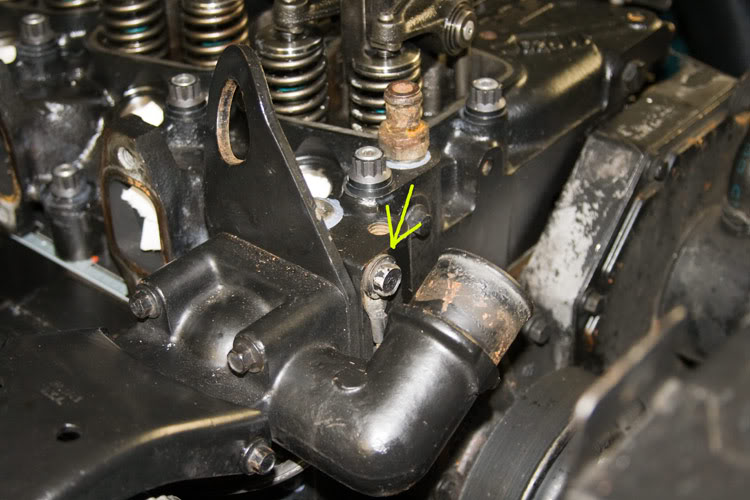
- Disconnect the alternator's ground on the head, just behind the engine coolant outlet nipple.
- Go pee and freshen-up your tea.
- Now switch to the driver's side of the engine and remove your charge-air plumbing if your truck's intercooled. No need in removing the intake feed-horn, etc. but do stuff a clean towel in there.
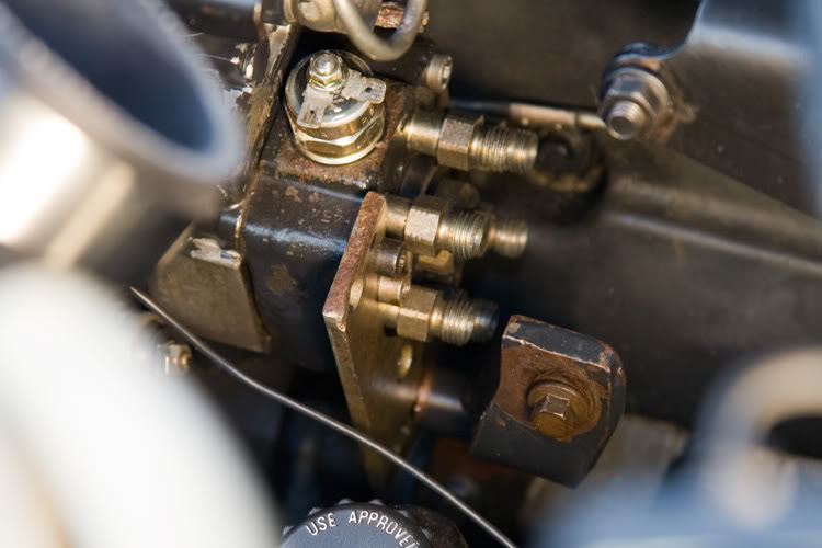
- Disconnect the AFC's boost reference tube from the injection pump and then remove the tube assembly from the head. You just as well go ahead and temporarily reinstall the mess on the IP so as not to lose anything.
- Disconnect the throttle rod from the injection pump along with the springs. Be sure to note where the springs go.
- Remove the throttle bell-crank's bracket assembly with the cables intact and set aside.
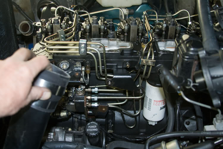
- Remove the fuel filter along with the two fuel lines that connect to the head just above the fuel filter. Tape them up or something to keep out the trash.
- Remove the High pressure fuel injection lines. It'll be fun working around the butt of the injection pump so get use to the notion. You'll find removing this one first will help getting to the next etc. Pay attention and use a back-up wrench on the delivery valves if needed (that which the lines connect to at the IP's butt).
- Remove the injector fuel return line.
Today, we're gonna replace the head-gasket on my 1993 Dodge/Cummins 5.9ltr intercooled 12 valve engine with an automatic transmission. Perhaps you're making general repairs such as an antifreeze leak. Such is the case with me, or at least it started that way. We won't be getting into performance modification stuff, just the basic service/replacement of the stock/OEM gasket.
On that note, be aware that my images used in this thread cover a number of years, involving a number of different projects. You may see the valve-covers off well before being instructed to remove them for example. Work with me.
As always ~ SAFETY FIRST!!
- Disconnect the Negative cable of your battery system.
- Chock the wheels and set the parking brake.
- Have a known good fire extinguisher close by.
- Have good lighting.
- Have a clean and orderly work area.
- Always exercise good working practice with your tools.
- Use safety goggles, gloves, masks, etc where appropriate.
- RTFM!
- I always clean the area I plan on working in the night before. Use the engine cleaner of your choice (follow the directions) and forcefully flush everything with a strong garden hose.
Finally know that I'm using the Chrysler Corporation 1993 Service Manual for the D&W 150-350 Ramcharger RWD truck as my guide in ensuring I hit all the bases. This thread is not to be considered "The Authoritive How-To" regarding working on your mess.
OK, fine . . . . .
- Spray the turbocharger and exhaust manifold bolts with your favorite penetrating oil. While you're at it, hit the turbochargers oil feed-line fittings where they enter the turbocharger.
- With the help of friends, remove the hood of the truck. Careful of the windshield! You might scribe around the hinge mounts so you can put things back together right. I just used the factory paint marks as reference.
- Drain the engine coolant. Always catch and contain the mess as it's poison never mind expensive. I end up using the turbocharger to intercooler pipe to get from the radiator's petcock to my bucket. I strain it if needed and put it right back in when complete.
- Drain the engine oil. I've found that most all restaurants use frying oil that comes as a five gallon plastic jug in a cardboard box. They won't mind you getting the empty containers out of their way. Makes it easy to take it to the local Auto-Zone or such that have the used oil recycling drums. It's free.
- If your truck's non-intercooled, this ought to be a good time to remove the charge-air cross-over pipe. Stuff a clean towel into the turbocharger's outlet, and the charge-air intake's feed-horn.
-Disconnect and remove the top radiator hose as well as the two cab heater hoses. Be careful tugging on the cab heat water valve and heater core connections. I've found it helpful to pinch the rubber hose here and there where it engages the connectors so as to first break the rubber/metal bond. Then pull them free.
- Remove the turbocharger assembly. The intake and exhaust plumbing first, then the oil feed-line. BE SURE to use a back-up wrench on the feed-line fittings. Be prepared for the actual oil tube to stick to it's fitting. You don't want it to turn with the fitting as you may wring the tube off so be patient with it. Follow that with disconnecting the oil drain line. As you remove the turbo, you'll find a single metal gasket between the turbo and exhaust manifold. I temporarily put the gasket, nuts and washers back on the manifold studs so I won't loose them.
With removal of the turbo, be sure to plug all the oil openings so as to ensure no trash gets in there. If you think you might not be able to stay off the oil supply tube where it connects to the engine oil filter assembly, go ahead and remove it using the same methods and precautions.
- Remove the exhaust manifold. I usually leave a bolt loose at each end till all the others are removed. Here again, to help keep trash out of things, stuff some paper towels into the head's exhaust ports.
- Now rest your back a bit and slip the serpentine belt off the alternator pulley.
- Disconnect the wires from the alternator being sure not to allow the studs to turn while you loosen things.
- Remove the alternator's top mounting bracket and swing the alternator down some so as to help clear the thermostat housing.
- Disconnect the alternator's ground on the head, just behind the engine coolant outlet nipple.
- Go pee and freshen-up your tea.
- Now switch to the driver's side of the engine and remove your charge-air plumbing if your truck's intercooled. No need in removing the intake feed-horn, etc. but do stuff a clean towel in there.
- Disconnect the AFC's boost reference tube from the injection pump and then remove the tube assembly from the head. You just as well go ahead and temporarily reinstall the mess on the IP so as not to lose anything.
- Disconnect the throttle rod from the injection pump along with the springs. Be sure to note where the springs go.
- Remove the throttle bell-crank's bracket assembly with the cables intact and set aside.
- Remove the fuel filter along with the two fuel lines that connect to the head just above the fuel filter. Tape them up or something to keep out the trash.
- Remove the High pressure fuel injection lines. It'll be fun working around the butt of the injection pump so get use to the notion. You'll find removing this one first will help getting to the next etc. Pay attention and use a back-up wrench on the delivery valves if needed (that which the lines connect to at the IP's butt).
- Remove the injector fuel return line.
 03-21-2009, 12:27 AM
#2
1st Generation Admin
Thread Starter
The injector fuel return line connects to the injection pump's fuel return line by way of a T fitting at the rear of the head, driver's side.
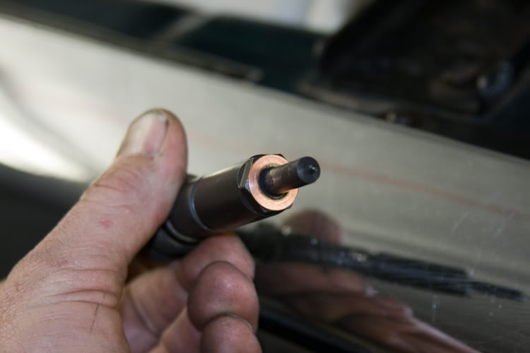
- Remove the injectors being sure to keep up with the copper washers between the injectors and the bottom of the bores. You may find some of the washers stick to the injector, while others stick to the bottom of the head's injector bore. You'll need a long, narrow "L" shaped pick to dig them out of the head (See the DTR 1st Gen Sticky for helpful hints and tools for removing stubborn injectors).
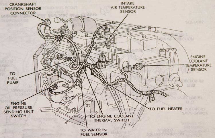
- Remove all the electrical lines starting at the front of the engine ~
* Crankshaft position sensor plug.
* Throttle position sensor plug (automatic transmission only).
* KSB switch plug.
* Fuel cut-off solenoid connections.
Moving back toward the cab a little .. .
* On the intake log cover-plate, unplug the KSB air temperature sensor.
* Unplug the charge-air heater air temperature sensor.
* Disconnect the power lines to the charge-air heaters.
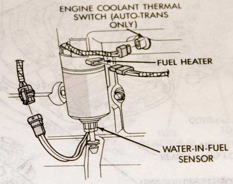
* On the cab end/bottom of the intake log, disconnect the fuel heater.
* Disconnect the engine coolant temperature switch (automatic transmission only).
* And finally disconnect the engine temperature sending unit.
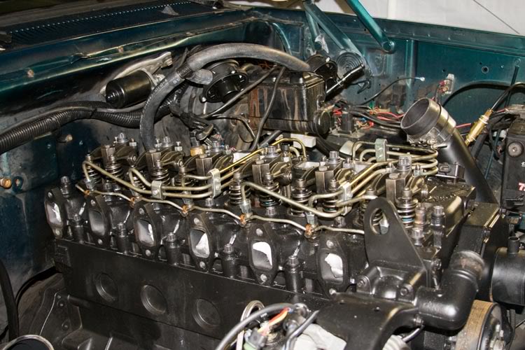
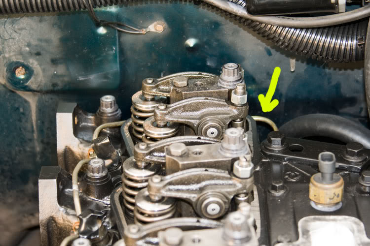
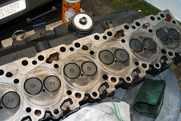
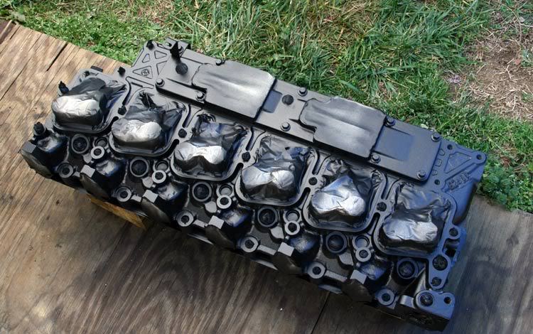
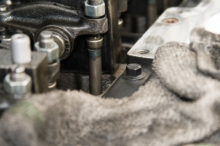
- Remove the valve-covers.
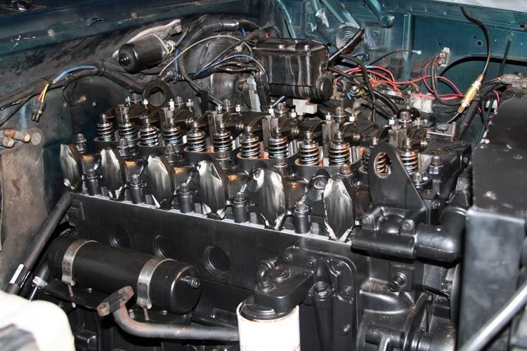
- Loosen all the valve-lash adjustment jamb-nuts and screws. Go ahead and loosen them to the point any valve-spring pressure is relieved.
NOTE: Loosen the adjustment screws so that one can move the rocker-levers say . . . about a 1/16 of an inch. Make them all pretty close in measurement. It doesn't have to be rocket science like. You'll understand why when we go to putting it all back together.

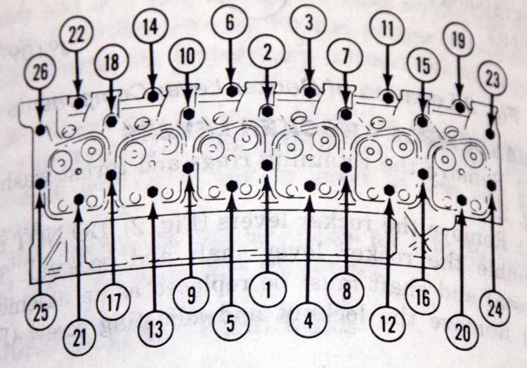
- Loosen and remove all the cylinder head bolts starting in the center, and work your way out in a circular pattern. Here's a diagram as to how I'm talking about . . .
- Completely loosen the remaining smaller bolts that hold the rocker-arm pedestals to the head.
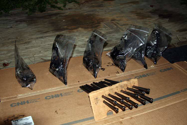
I've always kept any removed parts segregated so that they will go back where they came. In this case, I take some quart size sandwich bags and number them with a permanent marker. 1, 2, 3, etc.
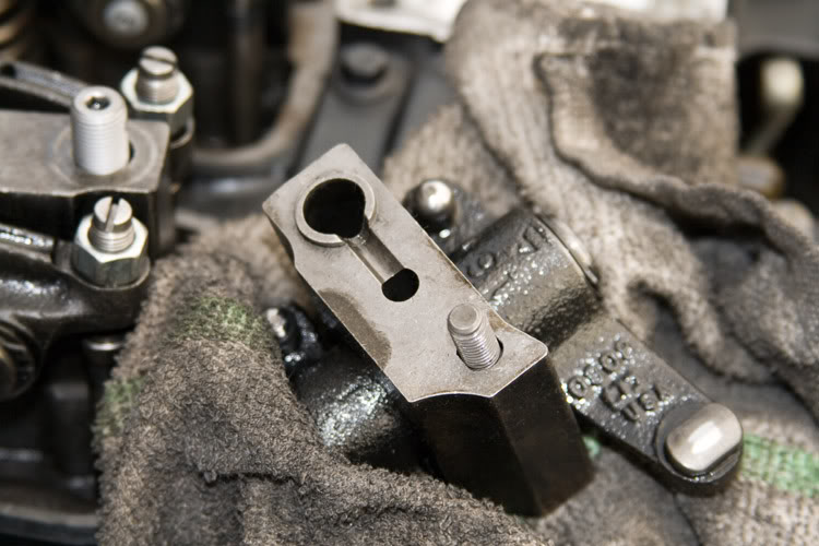
- Lift and remove the individual rocker-arm pedestal assemblies, complete with the small bolts and place the assemblies in the sandwich bags.
In keeping with the above segregation, I take a piece of cardboard, punch six pairs of holes in it, in a line. I number each pair; 1, 2, 3, etc. I also note each line of six holes as; Intake, and the other Exhaust.
- Now remove the valve push-rods from each cylinder and place them in the appropriate hole of the cardboard.
The point of all the bagging is that with time and normal use, the valve-train components have worn into one another. Inadvertently swapping the push-rods around for example, may very well result in sudden, greatly exaggerated wear and early failure. If you've ever had to repair a bicycle or motorcycle chain, you know a new chain will not last on used sprockets. Not long at all.
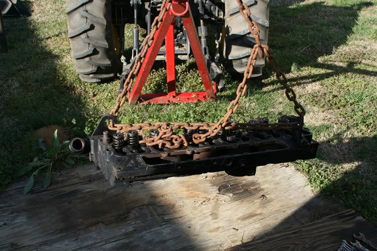
- On the rear of the intake log, adjacent to the brake master cylinder, you'll find a bracket bolted to the intake log. Remove those two bolts and flip the bracket over. Position the bracket so the lifting hole is outward (you'll figure it out) and bolt the bracket back to the head as such. Torque the bolts to 57 ft/lbs. This will be the rear lifting attachment point.
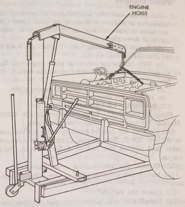
- Attach your lifting chains or cables to the lifting brackets at the front and rear of the head. BE SURE your chains or cables are in good working order and rated for the load. The head assembly weighs over 100 pounds if I remember correctly.
- Remove the injectors being sure to keep up with the copper washers between the injectors and the bottom of the bores. You may find some of the washers stick to the injector, while others stick to the bottom of the head's injector bore. You'll need a long, narrow "L" shaped pick to dig them out of the head (See the DTR 1st Gen Sticky for helpful hints and tools for removing stubborn injectors).
- Remove all the electrical lines starting at the front of the engine ~
* Crankshaft position sensor plug.
* Throttle position sensor plug (automatic transmission only).
* KSB switch plug.
* Fuel cut-off solenoid connections.
Moving back toward the cab a little .. .
* On the intake log cover-plate, unplug the KSB air temperature sensor.
* Unplug the charge-air heater air temperature sensor.
* Disconnect the power lines to the charge-air heaters.
* On the cab end/bottom of the intake log, disconnect the fuel heater.
* Disconnect the engine coolant temperature switch (automatic transmission only).
* And finally disconnect the engine temperature sending unit.
- Remove the valve-covers.
- Loosen all the valve-lash adjustment jamb-nuts and screws. Go ahead and loosen them to the point any valve-spring pressure is relieved.
NOTE: Loosen the adjustment screws so that one can move the rocker-levers say . . . about a 1/16 of an inch. Make them all pretty close in measurement. It doesn't have to be rocket science like. You'll understand why when we go to putting it all back together.
- Loosen and remove all the cylinder head bolts starting in the center, and work your way out in a circular pattern. Here's a diagram as to how I'm talking about . . .
- Completely loosen the remaining smaller bolts that hold the rocker-arm pedestals to the head.
I've always kept any removed parts segregated so that they will go back where they came. In this case, I take some quart size sandwich bags and number them with a permanent marker. 1, 2, 3, etc.
- Lift and remove the individual rocker-arm pedestal assemblies, complete with the small bolts and place the assemblies in the sandwich bags.
In keeping with the above segregation, I take a piece of cardboard, punch six pairs of holes in it, in a line. I number each pair; 1, 2, 3, etc. I also note each line of six holes as; Intake, and the other Exhaust.
- Now remove the valve push-rods from each cylinder and place them in the appropriate hole of the cardboard.
The point of all the bagging is that with time and normal use, the valve-train components have worn into one another. Inadvertently swapping the push-rods around for example, may very well result in sudden, greatly exaggerated wear and early failure. If you've ever had to repair a bicycle or motorcycle chain, you know a new chain will not last on used sprockets. Not long at all.
- On the rear of the intake log, adjacent to the brake master cylinder, you'll find a bracket bolted to the intake log. Remove those two bolts and flip the bracket over. Position the bracket so the lifting hole is outward (you'll figure it out) and bolt the bracket back to the head as such. Torque the bolts to 57 ft/lbs. This will be the rear lifting attachment point.
- Attach your lifting chains or cables to the lifting brackets at the front and rear of the head. BE SURE your chains or cables are in good working order and rated for the load. The head assembly weighs over 100 pounds if I remember correctly.
03-21-2009, 12:28 AM
#3
1st Generation Admin
Thread Starter
- Lift the head from the block using means that are SAFE! If you use the John Deere as I did, you'll do well having someone you trust work the tractor lift while you guide the head up and out of the engine bay. I found it best to rotate the head counter-clockwise as it came off the block so as to clear the wiper motor and fan shroud.
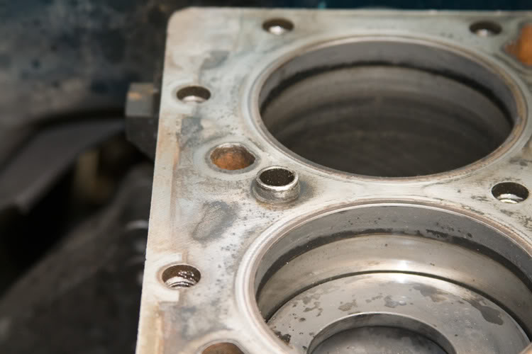
Be aware that there are two, what look like thin pieces of pipe or dowels (large diameter, thin-wall roll-pins) that are used to locate the head and gasket on the block. With removing the head, you may find one has stuck in the block, with the other stuck in the head. Or versy-vicy. Just keep up with them (we'll end up sticking them both in the block later).

Alright, the head's off the block, now what?
Let's clean things up so as to better see what we've got.
- The FSM want you to clean the head's injector bores with a nylon or brass brush. Lacking such, I had my Son ( ) use a large flat-blade screw-driver with a towel over the business end.
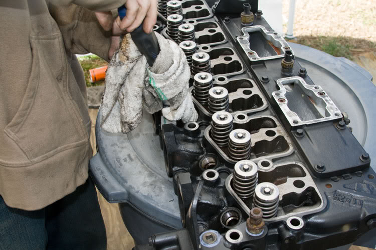
What ever method you use, just clean up the seat of the bore along with the sides.
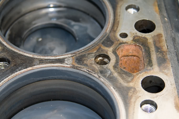
- Scrape any gasket stuff from all the gasketed surfaces.
- To clean the head's block surface, the FSM wants you to use some 400 grid paper. Grid? Might be a typo? I just used one of the green scouring pads wet with some penetrating oil. We're not after a mirror finish, just get the carbon boogers off. You'll most likely find the iron's stained like mine.
- Now wash the entire thing with some strong sudsy hot water. Rinse well and blow dry it with some compressed air if you have it.
- Now clean the deck of the block in the same manner.
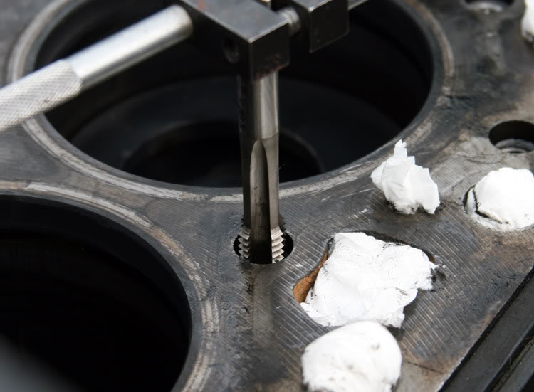
- The FSM doesn't mention it, but I strongly recommend you at least chase the threads of the head-bolt holes in the block. Full thread engagement of both the head-bolt and block are crucial to realize the full clamping force of your fastening system (strong bolts are crap if the threads are whacked).
Besides, you'll find those bolt holes at the exhaust manifold side are loaded with carbon. The long bolts for the rocker bosses are loaded with thick oily goo. We need to clean all that out.
And,
If you plan on installing studs, you need to "Bottom Tap" the bolt holes. You can read about the general process here ~ https://www.dieseltruckresource.com/...d.php?t=213091
Otherwise just run a M12x1.75 tap in and out of the holes repeatedly till the tap runs smoothly. Those bolt holes with the hard carbon build up may crunch some so expect that. Some penetrating oil will help.
Be aware that there are two, what look like thin pieces of pipe or dowels (large diameter, thin-wall roll-pins) that are used to locate the head and gasket on the block. With removing the head, you may find one has stuck in the block, with the other stuck in the head. Or versy-vicy. Just keep up with them (we'll end up sticking them both in the block later).
Alright, the head's off the block, now what?
Let's clean things up so as to better see what we've got.
- The FSM want you to clean the head's injector bores with a nylon or brass brush. Lacking such, I had my Son (
) use a large flat-blade screw-driver with a towel over the business end.What ever method you use, just clean up the seat of the bore along with the sides.
- Scrape any gasket stuff from all the gasketed surfaces.
- To clean the head's block surface, the FSM wants you to use some 400 grid paper. Grid? Might be a typo? I just used one of the green scouring pads wet with some penetrating oil. We're not after a mirror finish, just get the carbon boogers off. You'll most likely find the iron's stained like mine.
- Now wash the entire thing with some strong sudsy hot water. Rinse well and blow dry it with some compressed air if you have it.
- Now clean the deck of the block in the same manner.
- The FSM doesn't mention it, but I strongly recommend you at least chase the threads of the head-bolt holes in the block. Full thread engagement of both the head-bolt and block are crucial to realize the full clamping force of your fastening system (strong bolts are crap if the threads are whacked).
Besides, you'll find those bolt holes at the exhaust manifold side are loaded with carbon. The long bolts for the rocker bosses are loaded with thick oily goo. We need to clean all that out.
And,
If you plan on installing studs, you need to "Bottom Tap" the bolt holes. You can read about the general process here ~ https://www.dieseltruckresource.com/...d.php?t=213091
Otherwise just run a M12x1.75 tap in and out of the holes repeatedly till the tap runs smoothly. Those bolt holes with the hard carbon build up may crunch some so expect that. Some penetrating oil will help.
03-21-2009, 12:29 AM
#4
1st Generation Admin
Thread Starter
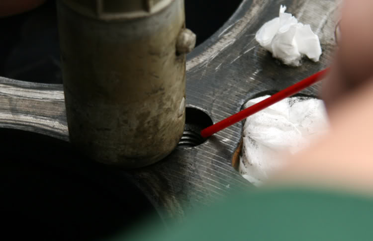
- Now flush all the crunchies out of the bolt holes. I used some non-flammable  brake cleaner stuff with the little tube to get to the bottom of the holes. Then with a vacuum cleaner slurping on the thing, flushed it all out. Some compressed air through a 1/4" soft copper tube works good to. Ummm, .. . . what's that all over the ceiling? DOH!!
OK, if you're just replacing the head-gasket, it's about time to start putting it all back together. Else, you might be planning on some machine work. Just for sport, here's some FSM stuff for figuring out what you have.
NOTE: If you're the sole original owner of the truck, then you should know it's history, otherwise . . . . .
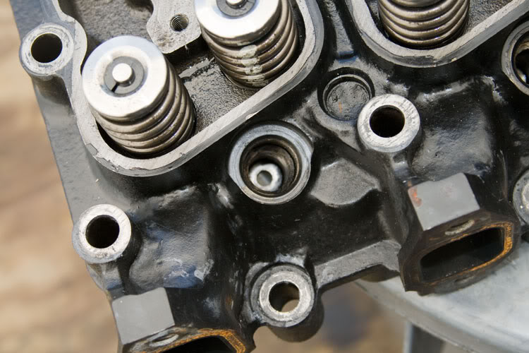
- You need to check the head between the cylinders for any grooves or etching where there might be some cylinder-to-cylinder leaking.
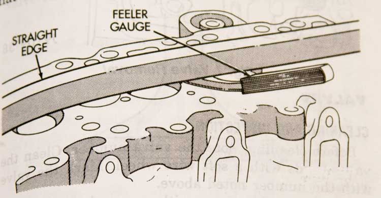
- You'll need to check that the head isn't warped too bad. The book says ~
So if the head is smiling or frowning, you may need to have it milled. Has it been milled before? If it has, and if the mechanic marked the head like he should have, then you'll find the marks at the rear bottom right of the head. The book says ~
And finally, if you've dinged a valve and think you need a valve job, the book says ~
If the head's good to go and clean, you'd just as well go ahead and tape it up and paint it.
Alrighty then,
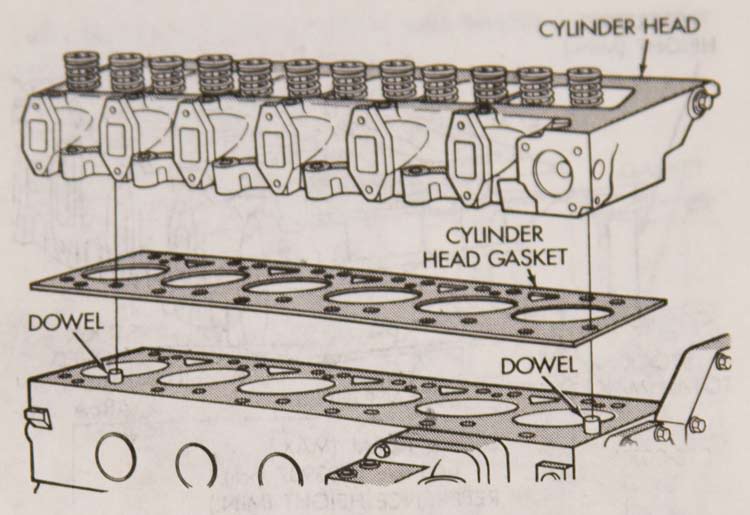
- Put the two dowels into the holes in the block, one up front . .. . .
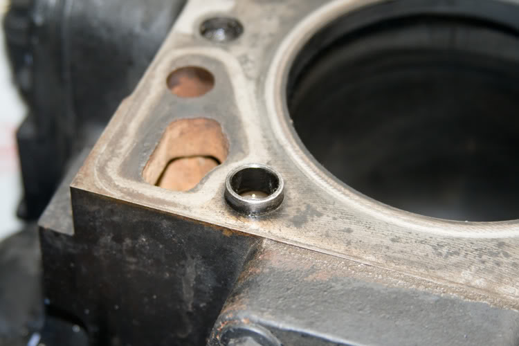
- And then the other toward the back . . . .
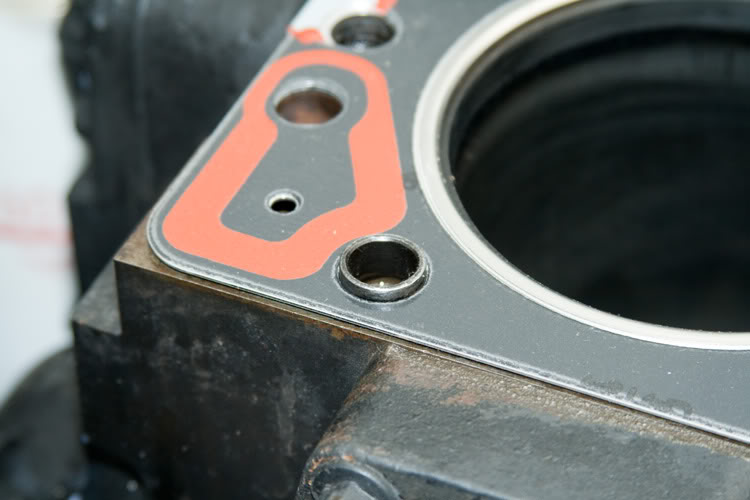
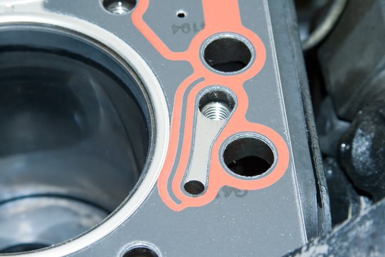
- Now set the new gasket in place. Use the dowels to properly locate the gasket.
brake cleaner stuff with the little tube to get to the bottom of the holes. Then with a vacuum cleaner slurping on the thing, flushed it all out. Some compressed air through a 1/4" soft copper tube works good to. Ummm, .. . . what's that all over the ceiling? DOH!! OK, if you're just replacing the head-gasket, it's about time to start putting it all back together. Else, you might be planning on some machine work. Just for sport, here's some FSM stuff for figuring out what you have.
NOTE: If you're the sole original owner of the truck, then you should know it's history, otherwise . . . . .
- You need to check the head between the cylinders for any grooves or etching where there might be some cylinder-to-cylinder leaking.
- You'll need to check that the head isn't warped too bad. The book says ~
Originally Posted by The Book
Check for head distortion. The distortion of the combustion deck face is not to exceed 0.010 mm (0.0004 inch) in any 50.8 mm (2.00 inch) diameter. Overall variation end to end or side to side 0.30 mm (0.012 inch).
So if the head is smiling or frowning, you may need to have it milled. Has it been milled before? If it has, and if the mechanic marked the head like he should have, then you'll find the marks at the rear bottom right of the head. The book says ~
Originally Posted by The Book
The cylinder head combustion deck may be refaced in whatever increments necessary to clean up the surface and maintain the surface finish and flatness tolerances. The combined total of stock removed must not exceed 1.00 mm (0.03937 inch). The amount of stock removed each time must be steel stamped above the combustion deck edge, on the lower right-hand corner of the rear face. Check valve protrusion after head surface refacing.
Surface finish requirements are 1.5 - 3.2 micrometer (60-126 microinch).
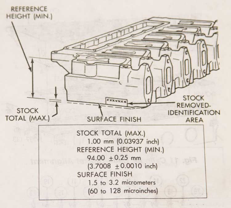
Surface finish requirements are 1.5 - 3.2 micrometer (60-126 microinch).
And finally, if you've dinged a valve and think you need a valve job, the book says ~
Originally Posted by The Book
Cylinder head with integral valve seats can only be ground once. Previously ground integral seats must be replaced with service seats.
One X stamped into the head casting identify seats that have been ground previously.
Two XX's stamped on the head indicate service seats have been installed. Service seats can be ground.
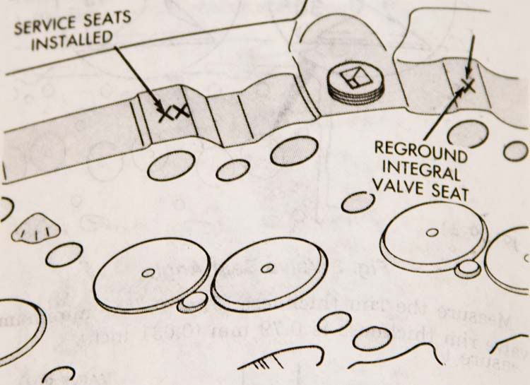
On the integral seat head, if 0.254 mm (0.010 inch) or more has been removed from the head combustion surface, service seats must be installed.
To determine if the head has been previously resurfaced, before calculating valve depth, proceed as follows:
- Check the rear lower right corner of the head for stamping that would indicate previous resurfacing (eg .003).
- To verify the information, or if no amount is indicated, measure the head height.
- If the head height is 94.75 mm (3.730 inch) or greater, the valve seats may be ground, if they have not been ground previously.
One X stamped into the head casting identify seats that have been ground previously.
Two XX's stamped on the head indicate service seats have been installed. Service seats can be ground.
On the integral seat head, if 0.254 mm (0.010 inch) or more has been removed from the head combustion surface, service seats must be installed.
To determine if the head has been previously resurfaced, before calculating valve depth, proceed as follows:
- Check the rear lower right corner of the head for stamping that would indicate previous resurfacing (eg .003).
- To verify the information, or if no amount is indicated, measure the head height.
- If the head height is 94.75 mm (3.730 inch) or greater, the valve seats may be ground, if they have not been ground previously.
If the head's good to go and clean, you'd just as well go ahead and tape it up and paint it.
Alrighty then,
- Put the two dowels into the holes in the block, one up front . .. . .
- And then the other toward the back . . . .
- Now set the new gasket in place. Use the dowels to properly locate the gasket.
03-21-2009, 12:31 AM
#5
1st Generation Admin
Thread Starter
- Once again, in a safe manner, raise the head and position it over the gasket. Gently set the head to the block using the dowels to locate it.
- Flip the rear engine lift bracket back over to the way it was.
- Install the push rods. BE SURE to have the push rod actually sit in the lifter. It is possible to place them kinda sideways only to cause problems later so be sure to feel for a "suck" when you try to lift the rod out of the lifter some.
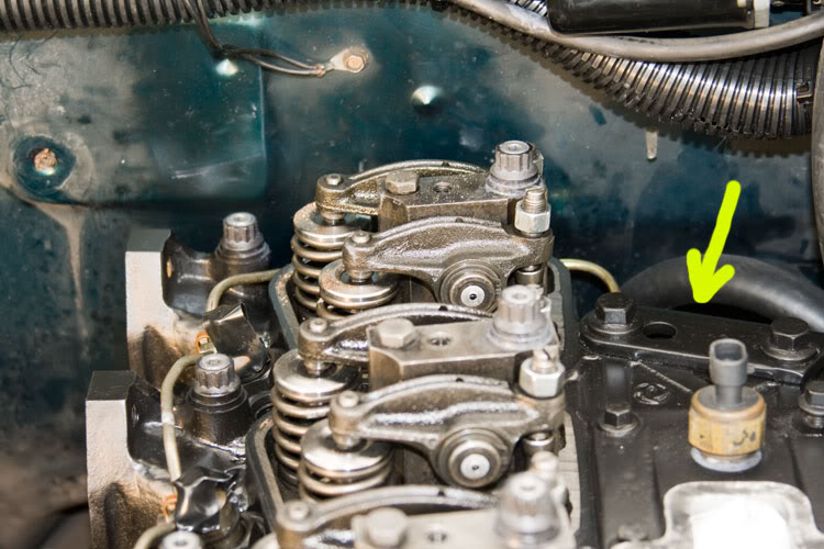
- Now we want to install the valve rocker assemblies. If you look at the bottom of the rocker pedestals, you'll notice a ring around where the head-bolt goes through. You need to make sure that ring is nested into the head. Don't, the assembly will sit crooked.
NOTE: Remember where we loosened the adjustment screws so the rockers would move about 1/16 of an inch? When reinstalling the rocker pedestal assemblies, if you find that things won't sit and nest to the head seemingly because a push-rod is too tall, that push-rod is NOT seated in it's lifter. The push-rod is actually sitting off to the side of it's lifter. You must reposition the push-rod so it's nested into the rod socket of the lifter. Don't, things WILL break catastrophically!
Remember all the oily goo in the head-bolt holes under the rockers? On it's way to the rockers and valve stems, the lubricating engine oil must first come up through the block, and by way of a passage in the head-gasket, the oil flows over to the long head-bolt where the oil flows up through the head.
The oil then flows through that groove in the base of the pedestal over to a passageway through the pedestal and to the rocker bearings, etc.
Kewl!
- I'm hoping that by now, you've cleaned the threads of your head-bolts if you haven't got new ones. Once again, if you're gonna reuse the original head-bolts, strongly consider chasing those threads as well. Now lubricate the bolt threads with your favorite clean engine oil. Get under the bolt heads to.
- The bolts are of three different sizes. The short ones go on the exhaust manifold side of the head. The middle size bolts go into the two middle rows. The longest bolts go into the rocker arm pedestals.
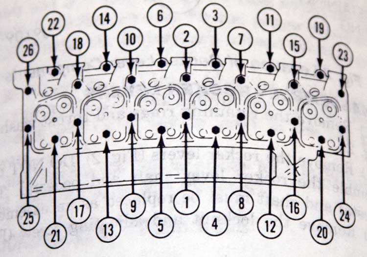
- Tighten the bolts as follows ~ *
STEP ONE: Tighten all bolts, in sequence as shown below, to 66 ft/lbs torque. Check the torque. If lower than 66 ft/lbs, tighten to this torque.
STEP TWO: Tighten all the long bolts (nos 4, 5, 12, 13, 20 and 21), in sequence to 89 ft/lbs. Check the torque. If lower than 89 ft/lbs, tighten to this torque.
STEP THREE: Tighten all bolts, in sequence an additional 90 degrees.
* NOTE: It is my understanding that the 1991.5 and BACK heads were fastened with different head-bolts that were torqued in a different manner. Everybody strongly recommends that one upgrades to the newer if you pull them out for any reason. In fact, I think the newer are all you can get now.
- Install the smaller rocker pedestal bolts and tighten to 18 ft/lbs.
- Adjust the valve clearance (Again, peek in "The Sticky" found in the 1st Gen board of these forums for helpful guides).
- Install the valve covers and torque those bolts to 18 ft/lbs.
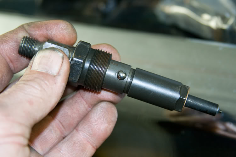
- Install the injectors and associated washers. Be sure to have the ball in the side of the injector, nest in the groove in the side of the injector bores of the head. Torque the retaining nuts to 44 ft/lbs.
- Install the injector fuel return line. You should be able to reuse the original copper sealing washer things. Don't wring off the little hollow bolts (only 6 ft/lbs if you've got a torque wrench that'll get in there).
- Install the injector high pressure fuel lines. It will be fun so be patient. As before, be sure to use a back-up wrench on the injection pump's delivery valves. ABOVE ALL, be sure to see that none of the high pressure fuel injection lines touch anything other than the clamps that hold them to one another. Bend them gently by whatever means to ensure they don't contact any surfaces where they would "Worry" a hole in themselves with the ballooning of the tubes with normal operation. Cut a corner here, and you WILL have diesel fuel squirting everywhere in short order. Count on it. Reinstall ALL of the fuel line clamp assemblies so as to secure it all. You should probably leave the injector connection a little loose for "Burping" the air from the lines later.
- Install the fuel filter.
- Connect the two fuel lines to the head just above the fuel filter.
- Connect all the electrical lines.
- Reinstall the boost reference tube to the head and AFC head of the injection pump.
- Install the throttle bell-crank assembly with cables to it's bracket.
- Connect the throttle rod to the injection pump.
- Install the throttle and transmission TV return springs.
- Install the exhaust manifold. As with the head, tighten the bolts in a circular pattern, from the center out. Torque the bolts to 32 ft/lbs. I use high temperature anti-seize on my manifold bolts.
- Install the turbocharger. The turbo mounting nuts are torqued to 75 in/lbs if you've a wrench for it. The turbo oil drain bolts go to 18 ft/lbs. Before screwing in the oil supply tube, pour an ounce or so of clean engine oil in the turbo's oil inlet hole. This will prime things so to speak. Here again, I use the anti-seize on all the mounting nuts as well as the oil supply tube fittings (if you got the thing out without messing it up, you'll understand).
- Replace the engine oil filter (be sure to fill it first).
- Reconnect your exhaust down-pipe as well as the tube from the air filter.
- Swing the alternator back up and reinstall the upper mounting bracket.
- Reconnect the cables to the alternator including that ground cable that goes on the head behind the radiator hose thing.
- Slip the serpentine belt back in place.
- Reinstall the cab heater hoses along with the upper radiator hose.
- Refill the engine coolant system with the antifreeze you collected and saved in starting this mess.
- Refill the engine with lubricating oil.
- As with any work that opens the high pressure fuel system, you'll need to bleed the air from the filter and high pressure lines. Be sure to tighten the injector lines at the injectors we left loose earlier.
- Being watchful of the windshield, reinstall the truck's hood using the paint marks and such to line it up correctly.
- Connect the ground of your battery system.
- Fire the boy up and check all around for any leaks. Repair as needed.
- Clean up your mess and put away your tools.
I think that's everything. Y'all drive safe.
- Flip the rear engine lift bracket back over to the way it was.
- Install the push rods. BE SURE to have the push rod actually sit in the lifter. It is possible to place them kinda sideways only to cause problems later so be sure to feel for a "suck" when you try to lift the rod out of the lifter some.
- Now we want to install the valve rocker assemblies. If you look at the bottom of the rocker pedestals, you'll notice a ring around where the head-bolt goes through. You need to make sure that ring is nested into the head. Don't, the assembly will sit crooked.
NOTE: Remember where we loosened the adjustment screws so the rockers would move about 1/16 of an inch? When reinstalling the rocker pedestal assemblies, if you find that things won't sit and nest to the head seemingly because a push-rod is too tall, that push-rod is NOT seated in it's lifter. The push-rod is actually sitting off to the side of it's lifter. You must reposition the push-rod so it's nested into the rod socket of the lifter. Don't, things WILL break catastrophically!
Remember all the oily goo in the head-bolt holes under the rockers? On it's way to the rockers and valve stems, the lubricating engine oil must first come up through the block, and by way of a passage in the head-gasket, the oil flows over to the long head-bolt where the oil flows up through the head.
The oil then flows through that groove in the base of the pedestal over to a passageway through the pedestal and to the rocker bearings, etc.
Kewl!
- I'm hoping that by now, you've cleaned the threads of your head-bolts if you haven't got new ones. Once again, if you're gonna reuse the original head-bolts, strongly consider chasing those threads as well. Now lubricate the bolt threads with your favorite clean engine oil. Get under the bolt heads to.
- The bolts are of three different sizes. The short ones go on the exhaust manifold side of the head. The middle size bolts go into the two middle rows. The longest bolts go into the rocker arm pedestals.
- Tighten the bolts as follows ~ *
STEP ONE: Tighten all bolts, in sequence as shown below, to 66 ft/lbs torque. Check the torque. If lower than 66 ft/lbs, tighten to this torque.
STEP TWO: Tighten all the long bolts (nos 4, 5, 12, 13, 20 and 21), in sequence to 89 ft/lbs. Check the torque. If lower than 89 ft/lbs, tighten to this torque.
STEP THREE: Tighten all bolts, in sequence an additional 90 degrees.
* NOTE: It is my understanding that the 1991.5 and BACK heads were fastened with different head-bolts that were torqued in a different manner. Everybody strongly recommends that one upgrades to the newer if you pull them out for any reason. In fact, I think the newer are all you can get now.
- Install the smaller rocker pedestal bolts and tighten to 18 ft/lbs.
- Adjust the valve clearance (Again, peek in "The Sticky" found in the 1st Gen board of these forums for helpful guides).
- Install the valve covers and torque those bolts to 18 ft/lbs.
- Install the injectors and associated washers. Be sure to have the ball in the side of the injector, nest in the groove in the side of the injector bores of the head. Torque the retaining nuts to 44 ft/lbs.
- Install the injector fuel return line. You should be able to reuse the original copper sealing washer things. Don't wring off the little hollow bolts (only 6 ft/lbs if you've got a torque wrench that'll get in there).
- Install the injector high pressure fuel lines. It will be fun so be patient. As before, be sure to use a back-up wrench on the injection pump's delivery valves. ABOVE ALL, be sure to see that none of the high pressure fuel injection lines touch anything other than the clamps that hold them to one another. Bend them gently by whatever means to ensure they don't contact any surfaces where they would "Worry" a hole in themselves with the ballooning of the tubes with normal operation. Cut a corner here, and you WILL have diesel fuel squirting everywhere in short order. Count on it. Reinstall ALL of the fuel line clamp assemblies so as to secure it all. You should probably leave the injector connection a little loose for "Burping" the air from the lines later.
- Install the fuel filter.
- Connect the two fuel lines to the head just above the fuel filter.
- Connect all the electrical lines.
- Reinstall the boost reference tube to the head and AFC head of the injection pump.
- Install the throttle bell-crank assembly with cables to it's bracket.
- Connect the throttle rod to the injection pump.
- Install the throttle and transmission TV return springs.
- Install the exhaust manifold. As with the head, tighten the bolts in a circular pattern, from the center out. Torque the bolts to 32 ft/lbs. I use high temperature anti-seize on my manifold bolts.
- Install the turbocharger. The turbo mounting nuts are torqued to 75 in/lbs if you've a wrench for it. The turbo oil drain bolts go to 18 ft/lbs. Before screwing in the oil supply tube, pour an ounce or so of clean engine oil in the turbo's oil inlet hole. This will prime things so to speak. Here again, I use the anti-seize on all the mounting nuts as well as the oil supply tube fittings (if you got the thing out without messing it up, you'll understand).
- Replace the engine oil filter (be sure to fill it first).
- Reconnect your exhaust down-pipe as well as the tube from the air filter.
- Swing the alternator back up and reinstall the upper mounting bracket.
- Reconnect the cables to the alternator including that ground cable that goes on the head behind the radiator hose thing.
- Slip the serpentine belt back in place.
- Reinstall the cab heater hoses along with the upper radiator hose.
- Refill the engine coolant system with the antifreeze you collected and saved in starting this mess.
- Refill the engine with lubricating oil.
- As with any work that opens the high pressure fuel system, you'll need to bleed the air from the filter and high pressure lines. Be sure to tighten the injector lines at the injectors we left loose earlier.
- Being watchful of the windshield, reinstall the truck's hood using the paint marks and such to line it up correctly.
- Connect the ground of your battery system.
- Fire the boy up and check all around for any leaks. Repair as needed.
- Clean up your mess and put away your tools.
I think that's everything. Y'all drive safe.
03-21-2009, 12:55 AM
#7
Registered User
Trending Topics
03-21-2009, 11:37 AM
#11
DTR's "Cooler than ice cubes 14 miles North of North Pole" member
Join Date: Oct 2006
Location: 14mi North of North Pole
Posts: 1,797
Likes: 0
Received 9 Likes
on
8 Posts
Originally Posted by BC847
- Go pee and freshen-up your tea.

Great Job as always BC!
 03-21-2009, 05:55 PM
#12
Registered User
And yet ANOTHER great write up...BC, you da man! As a side thought, have you ever considered writing service manuals for a living? I say that because your write-ups are waaaay more informative and detailed than the birdcage liners I am forced to use on a daily basis.....OUTSTANDING X1000!


