Rebuild Your CTD Starter
 03-12-2007, 08:31 PM
#1
1st Generation Admin
Thread Starter
This is another attempt to repay you good folks for all that I've learned here. This is by no means "The Authoritative How-To" regarding fixing your busted starter. These instructions are based solely on my experience with my heap exclusively. 
Over the last month, my starter has been occasionally presenting with a bunch of clicking and stuttering if you will. Poking around on the Internet I've found it's common for the starter itself to have issues such as worn contacts in the solenoid and worn brushes in the motor.
Further digging reveals there's a number of sources for the common parts available to us. Some offer upgraded components if need be.
In my case, the starter works with no apparent mechanical problems. Just typical worn electrically related components. Therefore, grinding gears and bearings aren't discussed here and may very well justify full replacement costs. Further, this discussion assumes all other aspects of your heap's starting system are in good working order (battery, cabling, relay, etc).
NOTE: Keep in mind I'm working on the stock, OEM style starter as installed by Dodge on a 1993 W250 4x4 ClubCab with automatic transmission. Another trucks mileage may vary.
READ ALL THESE INSTRUCTIONS BEFORE ATTEMPTING THIS WORK.
With that, let's get started.
As always ~ SAFETY FIRST!
- Chock the wheels
- Set the emergency/parking brake.
- Disconnect the Negative battery cable from the battery.
- Have a known good fire extinguisher within sight.
- Have a clean, uncluttered work area with good lighting.
- Be aware that you're gonna be working around the fuel lift-pump and associated plumbing.
If you're running one of the Old-School External Lubrication Systems, it'd be a good idea to pressure wash the engine bay top and bottom the night before.
Alright . ..
First you're gonna have to reach in from the top driver's side and disconnect the engine's crankcase vent tube. It's down behind the fuel filter toward the firewall and runs down the side of the engine between the block and starter. It's dead on top of one of the starter mounting bolts.
Now spray some WD40 or the like on the threads of the bolt that connects the battery cable to the starter solenoid.
Go ahead and remove the engine Start wire (the small wire) from the starter solenoid.
Now climb under the truck, driver's side, on your back with your head going toward the oil pan drain plug. Reach up between the engine and frame and loosen the battery cable connection to the starter solenoid. A 12 point box end wrench works best. I went through right next to the trans shifter linkage. You'll need to do this from under the truck as the nut's on there good and from that position, you can lean on it as is needed to get it loose. That's a copper alloy nut and bolt as best I can tell and as such seems to want to gall pretty easily. That's what the lubricant's for.
Now all that's left is to remove the mounting bolts. There's three of them (10mm / 12 point)
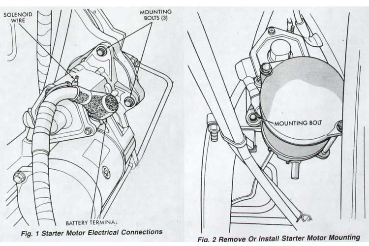
I found it best to remove the top-most bolt (from under the hood) and that closest to the block (from under the truck) first. Then, from under the truck, hold the starter with one hand, and remove the final bolt closest to the frame. Move the starter forward and down to remove.
It's greasy and heavy so be careful!
So setting it on the bench, here's what we have ~
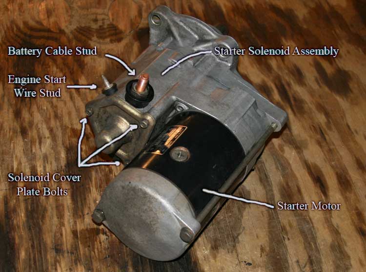
It wouldn't hurt to go ahead and clean the outside of the starter now.
Having done so, note that on either side of the starter solenoid, there's two copper studs. One as you know connects the battery cable to the solenoid (a big power switch), the other passes the 12VDC power to the starter motor.
Again, because the bolts tend to gall, spray them with a lubricant now.
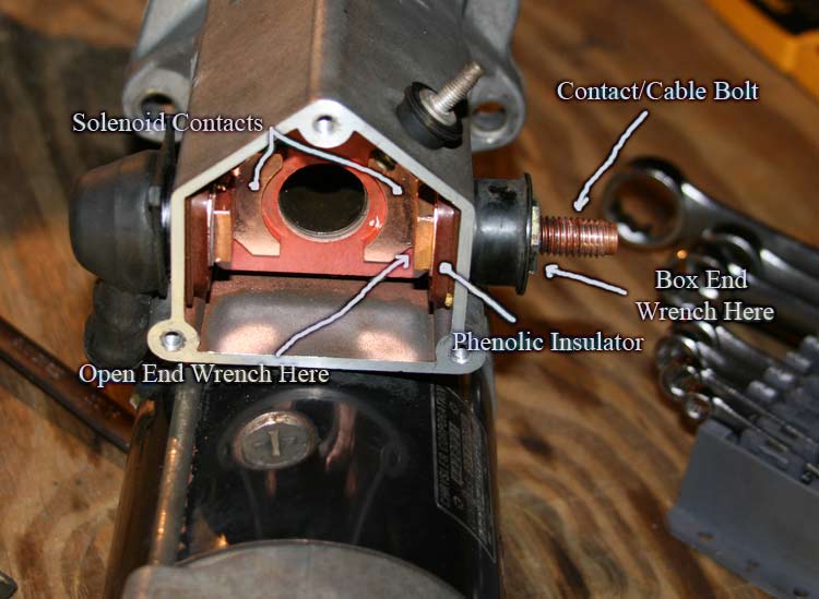
Now remove the three small screws that hold the cover plate to the solenoid. You'll need to hold the cover as the innards are spring loaded. Removing the cover plate, pull out the solenoid plunger assembly. It should come out with a long spring on the narrow shaft. If not, the spring's still in the solenoid coil housing along with a steel ball bearing. You may have to bump the starter on the bench to get the ball bearing out. Don't lose it.

Now, look inside the solenoid housing. You'll see the two contacts that will most likely appear burnt and pitted. We're going to replace those. They are held in place by those two copper bolts. Where those bolts pass through the solenoid housing, the bolts are insulated electrically by phenolic bushings.
We need to first remove the motor power cable from its bolt (under the rubber boot). Be aware of any binding so as to back off, and go again if you have to. We DON'T want the bolts to spin in the assembly! The worst case scenario is you break the brittle phenolic bushing. Do that, and you're in deep doodoo.
Having removed the motor cable, use a back-up wrench to hold the bolt heads in the housing while you remove the nuts. Notice that the battery cable bolt has a small wire connected inside the housing. This powers the solenoid coil. Don't damage it when removing the bolt. Resist any rocking of the bolts so as not to crack the phenolic bushings.
Based on my experience doing this job, I can't over stress how fragile those phenolic insulator bushings are. Specifically the bushing part that surrounds the bolt and insulates it going through the hole. I hadn't figured out the copper bolt galling thing and inadvertently let the bolt rock about its hole while initially taking it apart. I destroyed the little sleeve part. I literally had to whittle another sleeve from some phenolic stock I had. That's another book!
DON'T BRAKE THE PHENOLIC INSULATOR BUSHINGS!
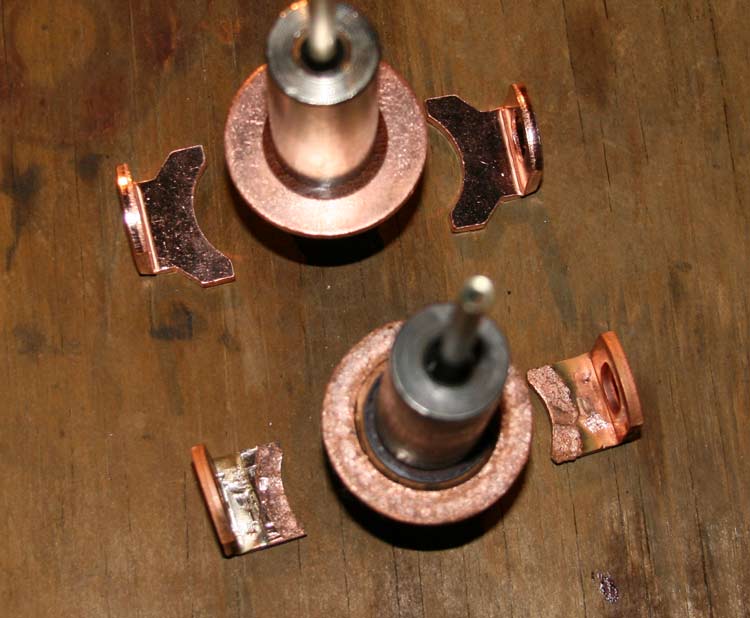
Here's the solenoid contacts and associated plunger as found in my heap. Notice the heavy pitting though it's not as bad as that shown on some of the parts suppliers websites.
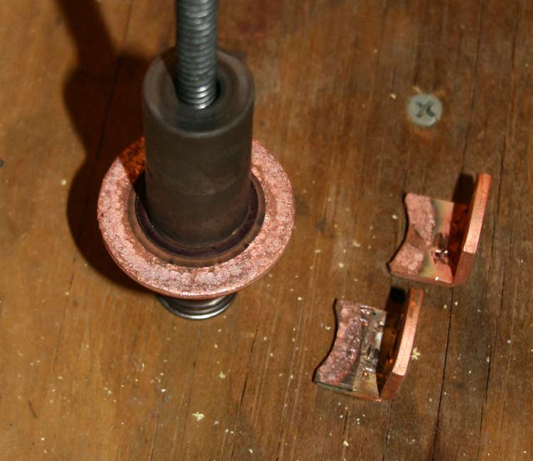
Now compare the old plunger and contacts to the new, upgraded style.
Over the last month, my starter has been occasionally presenting with a bunch of clicking and stuttering if you will. Poking around on the Internet I've found it's common for the starter itself to have issues such as worn contacts in the solenoid and worn brushes in the motor.
Further digging reveals there's a number of sources for the common parts available to us. Some offer upgraded components if need be.
In my case, the starter works with no apparent mechanical problems. Just typical worn electrically related components. Therefore, grinding gears and bearings aren't discussed here and may very well justify full replacement costs. Further, this discussion assumes all other aspects of your heap's starting system are in good working order (battery, cabling, relay, etc).
NOTE: Keep in mind I'm working on the stock, OEM style starter as installed by Dodge on a 1993 W250 4x4 ClubCab with automatic transmission. Another trucks mileage may vary.
READ ALL THESE INSTRUCTIONS BEFORE ATTEMPTING THIS WORK.
With that, let's get started.
As always ~ SAFETY FIRST!
- Chock the wheels
- Set the emergency/parking brake.
- Disconnect the Negative battery cable from the battery.
- Have a known good fire extinguisher within sight.
- Have a clean, uncluttered work area with good lighting.
- Be aware that you're gonna be working around the fuel lift-pump and associated plumbing.
If you're running one of the Old-School External Lubrication Systems, it'd be a good idea to pressure wash the engine bay top and bottom the night before.
Alright . ..
First you're gonna have to reach in from the top driver's side and disconnect the engine's crankcase vent tube. It's down behind the fuel filter toward the firewall and runs down the side of the engine between the block and starter. It's dead on top of one of the starter mounting bolts.
Now spray some WD40 or the like on the threads of the bolt that connects the battery cable to the starter solenoid.
Go ahead and remove the engine Start wire (the small wire) from the starter solenoid.
Now climb under the truck, driver's side, on your back with your head going toward the oil pan drain plug. Reach up between the engine and frame and loosen the battery cable connection to the starter solenoid. A 12 point box end wrench works best. I went through right next to the trans shifter linkage. You'll need to do this from under the truck as the nut's on there good and from that position, you can lean on it as is needed to get it loose. That's a copper alloy nut and bolt as best I can tell and as such seems to want to gall pretty easily. That's what the lubricant's for.
Now all that's left is to remove the mounting bolts. There's three of them (10mm / 12 point)
I found it best to remove the top-most bolt (from under the hood) and that closest to the block (from under the truck) first. Then, from under the truck, hold the starter with one hand, and remove the final bolt closest to the frame. Move the starter forward and down to remove.
It's greasy and heavy so be careful!
So setting it on the bench, here's what we have ~
It wouldn't hurt to go ahead and clean the outside of the starter now.
Having done so, note that on either side of the starter solenoid, there's two copper studs. One as you know connects the battery cable to the solenoid (a big power switch), the other passes the 12VDC power to the starter motor.
Again, because the bolts tend to gall, spray them with a lubricant now.
Now remove the three small screws that hold the cover plate to the solenoid. You'll need to hold the cover as the innards are spring loaded. Removing the cover plate, pull out the solenoid plunger assembly. It should come out with a long spring on the narrow shaft. If not, the spring's still in the solenoid coil housing along with a steel ball bearing. You may have to bump the starter on the bench to get the ball bearing out. Don't lose it.
Now, look inside the solenoid housing. You'll see the two contacts that will most likely appear burnt and pitted. We're going to replace those. They are held in place by those two copper bolts. Where those bolts pass through the solenoid housing, the bolts are insulated electrically by phenolic bushings.
We need to first remove the motor power cable from its bolt (under the rubber boot). Be aware of any binding so as to back off, and go again if you have to. We DON'T want the bolts to spin in the assembly! The worst case scenario is you break the brittle phenolic bushing. Do that, and you're in deep doodoo.
Having removed the motor cable, use a back-up wrench to hold the bolt heads in the housing while you remove the nuts. Notice that the battery cable bolt has a small wire connected inside the housing. This powers the solenoid coil. Don't damage it when removing the bolt. Resist any rocking of the bolts so as not to crack the phenolic bushings.
Based on my experience doing this job, I can't over stress how fragile those phenolic insulator bushings are. Specifically the bushing part that surrounds the bolt and insulates it going through the hole. I hadn't figured out the copper bolt galling thing and inadvertently let the bolt rock about its hole while initially taking it apart. I destroyed the little sleeve part. I literally had to whittle another sleeve from some phenolic stock I had. That's another book!
DON'T BRAKE THE PHENOLIC INSULATOR BUSHINGS!
Here's the solenoid contacts and associated plunger as found in my heap. Notice the heavy pitting though it's not as bad as that shown on some of the parts suppliers websites.
Now compare the old plunger and contacts to the new, upgraded style.

The following users liked this post:
D2.5k (12-14-2017)
03-12-2007, 08:32 PM
#2
1st Generation Admin
Thread Starter
Clean out the solenoid housing with a cloth being mindful of the solenoid coil wire.
Reassembly is pretty much the reverse of disassembly.
Let's start with the motor cable side (the left bolt as seen in my pictures).
Place the short copper bolt of the two through a new contact, and through a phenolic insulator bushing. If you look at the phenolic insulator bushing where the contact rests, you'll notice there's a U-shaped ridge. The "Open" end of that ridge will face the back of the solenoid housing and allow the contact to nest in the insulator bushing properly.
Having positioned the insulator bushing relative to the contact, pass the bolt through the solenoid housing seating the insulators bushing into the hole. Make sure the contact is flat and square against the back of the solenoid housing cavity. Slip one of the black plastic cup insulators over the bolt. You may have a small O-Ring on yours. Slip it on next followed by one thin washer and a thin nut. Using a back-up wrench to keep the bolt from spinning, snug it up without cracking the phenolic insulator bushing.
We'll not be connecting the motor power cable just yet pending other work, so keep up with the left over thin nut and washer.
Now do the same thing for the battery cable side (that on the right of my pictures). You'll notice this bolt's a little longer and has serrations toward the head. When you tighten things up, the bolt will pull the serrations into the new contact. Holding your back-up wrench, make sure you've got things straight as you begin to pull the bolt through and be mindful of the coil wire. You use the thick nut on this bolt.

I had considered cleaning and lubricating the new plunger, spring, and ball bearing but wasn't sure of what lubricant was best. So I opted to simply wipe them clean and leave it at that.
FYI ~ While the parts you've worked on thus far deal with the powering of the starter electrically, the plunger, spring and ball bearing are what engages the starters pinion gear with the ring gear of the engines flywheel/flex-plate. The ball bearing works just as the name implies and smooths the movement of those parts.
The ball bearing goes into the solenoid housing in the hole in the bottom of the plunger bore. The long spring goes around the long narrow shaft of the new plunger assembly. Stick the new plunger assembly, narrow spring first into the solenoid housing bore.
Move it in and out to see that it moves freely with no weird binding. Notice that as you push the plunger in, the starter pinion gear pops out the starters snout.
Clean the cover plate gasket, associated surfaces, and reinstall with the cover plate.

That wraps up servicing the starter solenoid. Now let's move on to the motor itself.
Reassembly is pretty much the reverse of disassembly.
Let's start with the motor cable side (the left bolt as seen in my pictures).
Place the short copper bolt of the two through a new contact, and through a phenolic insulator bushing. If you look at the phenolic insulator bushing where the contact rests, you'll notice there's a U-shaped ridge. The "Open" end of that ridge will face the back of the solenoid housing and allow the contact to nest in the insulator bushing properly.
Having positioned the insulator bushing relative to the contact, pass the bolt through the solenoid housing seating the insulators bushing into the hole. Make sure the contact is flat and square against the back of the solenoid housing cavity. Slip one of the black plastic cup insulators over the bolt. You may have a small O-Ring on yours. Slip it on next followed by one thin washer and a thin nut. Using a back-up wrench to keep the bolt from spinning, snug it up without cracking the phenolic insulator bushing.
We'll not be connecting the motor power cable just yet pending other work, so keep up with the left over thin nut and washer.
Now do the same thing for the battery cable side (that on the right of my pictures). You'll notice this bolt's a little longer and has serrations toward the head. When you tighten things up, the bolt will pull the serrations into the new contact. Holding your back-up wrench, make sure you've got things straight as you begin to pull the bolt through and be mindful of the coil wire. You use the thick nut on this bolt.
I had considered cleaning and lubricating the new plunger, spring, and ball bearing but wasn't sure of what lubricant was best. So I opted to simply wipe them clean and leave it at that.
FYI ~ While the parts you've worked on thus far deal with the powering of the starter electrically, the plunger, spring and ball bearing are what engages the starters pinion gear with the ring gear of the engines flywheel/flex-plate. The ball bearing works just as the name implies and smooths the movement of those parts.
The ball bearing goes into the solenoid housing in the hole in the bottom of the plunger bore. The long spring goes around the long narrow shaft of the new plunger assembly. Stick the new plunger assembly, narrow spring first into the solenoid housing bore.
Move it in and out to see that it moves freely with no weird binding. Notice that as you push the plunger in, the starter pinion gear pops out the starters snout.
Clean the cover plate gasket, associated surfaces, and reinstall with the cover plate.
That wraps up servicing the starter solenoid. Now let's move on to the motor itself.
The following users liked this post:
D2.5k (12-14-2017)
03-12-2007, 08:33 PM
#3
1st Generation Admin
Thread Starter
Going back to the general view, Loosen the two long bolts that attach the motor to the gear-case.
Supporting the weight of the motor, remove the two bolts. Holding the butt-plate and housing of the motor as a unit, pull the motor assembly out of the gear-case.
Place the motor on your bench, silver end down. Holding things carefully, lift the black housing while pushing down on the armature shaft. The armature will slip down through the brushes. The armature will stay as part of the end-plate, with the housing and brush holder assembly coming up as an assembly.
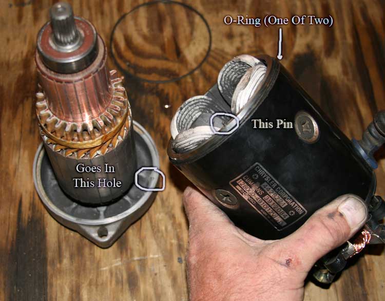
Before we go any further, there's a thin O-ring on each end of the motor housing. Don't damage them as they will be used again.

Set the armature/end-plate assembly aside for now.
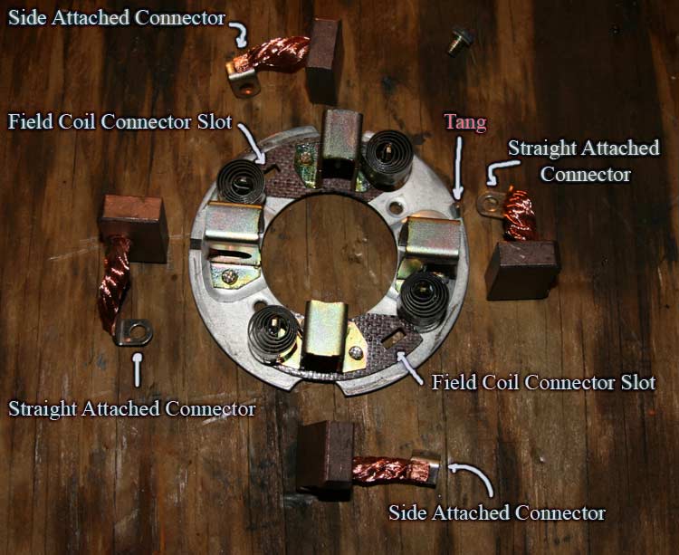
Place the housing on your bench with the brush assembly facing up. With the motor power cable facing away from you, notice the small tang that's facing you on the upper edge next to the brush holder (See pic).
With the assembly oriented as such, you'll see a brush connection (Phillips head screw) at 3:00 and 9:00. Those screws are attaching the brush(s) to the field windings in the housing. Removing those screws will allow you to separate the brush holder from the motor housing.

Place the brush holder on the bench, brushes up with the tang at about 2:30.
You'll notice the other two brushes have cables that connect to the holder frame itself with Phillips screws. Remove them.
With that we can now remove the old brushes. Pushing the brushes in and out of their holders, you can see the brush springs working. One brush at a time, take some needle-nose pliers and carefully rotate the spring back away from the butt of the brush. It'll take some fidgeting but with the spring out of the way, the brush will back out of the holder.
Comparing the old brushes with the new, I could see where mine were well worn. Perhaps not really to the point that replacement is required, but since we're in there . . .. .
Now's a good time to clean all that you can reach of the housing and brush holder.
OK, let's put it back together.
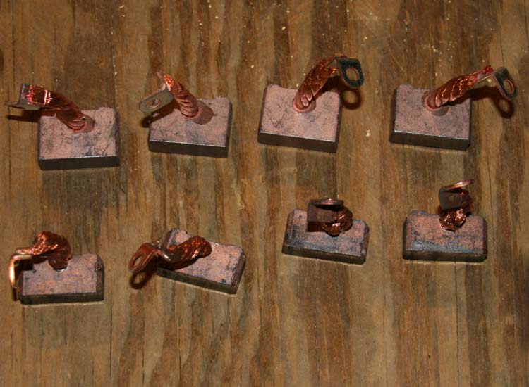
Looking hard at the ring connectors of the new brushes, you'll notice that there's actually two pairs of brushes. The only difference is the way the brush wire is attached to the ring connector. Two connect to the side, the others connect straight on.

Those brushes that connect to the brush holder frame use the straight connector. Those that connect to the field windings use the side connectors.
Understanding that, place the clean brush holder in front of you with the tang at 2:30 (as before) so you can locate where each brush goes. The brushes with the straight connectors go into the holders at 3:00 and 9:00. The other brushes go at 6:00 and 12:00. The brush wires face away from the brush springs.
When installing the brushes, try not to let the spring smack the brushes as they are somewhat fragile. An extra set of hands is helpful here.
Supporting the weight of the motor, remove the two bolts. Holding the butt-plate and housing of the motor as a unit, pull the motor assembly out of the gear-case.
Place the motor on your bench, silver end down. Holding things carefully, lift the black housing while pushing down on the armature shaft. The armature will slip down through the brushes. The armature will stay as part of the end-plate, with the housing and brush holder assembly coming up as an assembly.
Before we go any further, there's a thin O-ring on each end of the motor housing. Don't damage them as they will be used again.
Set the armature/end-plate assembly aside for now.
Place the housing on your bench with the brush assembly facing up. With the motor power cable facing away from you, notice the small tang that's facing you on the upper edge next to the brush holder (See pic).
With the assembly oriented as such, you'll see a brush connection (Phillips head screw) at 3:00 and 9:00. Those screws are attaching the brush(s) to the field windings in the housing. Removing those screws will allow you to separate the brush holder from the motor housing.
Place the brush holder on the bench, brushes up with the tang at about 2:30.
You'll notice the other two brushes have cables that connect to the holder frame itself with Phillips screws. Remove them.
With that we can now remove the old brushes. Pushing the brushes in and out of their holders, you can see the brush springs working. One brush at a time, take some needle-nose pliers and carefully rotate the spring back away from the butt of the brush. It'll take some fidgeting but with the spring out of the way, the brush will back out of the holder.
Comparing the old brushes with the new, I could see where mine were well worn. Perhaps not really to the point that replacement is required, but since we're in there . . .. .
Now's a good time to clean all that you can reach of the housing and brush holder.
OK, let's put it back together.
Looking hard at the ring connectors of the new brushes, you'll notice that there's actually two pairs of brushes. The only difference is the way the brush wire is attached to the ring connector. Two connect to the side, the others connect straight on.
Those brushes that connect to the brush holder frame use the straight connector. Those that connect to the field windings use the side connectors.
Understanding that, place the clean brush holder in front of you with the tang at 2:30 (as before) so you can locate where each brush goes. The brushes with the straight connectors go into the holders at 3:00 and 9:00. The other brushes go at 6:00 and 12:00. The brush wires face away from the brush springs.
When installing the brushes, try not to let the spring smack the brushes as they are somewhat fragile. An extra set of hands is helpful here.
The following users liked this post:
D2.5k (12-14-2017)
03-12-2007, 08:34 PM
#4
1st Generation Admin
Thread Starter
Using two of the Phillips head screws, reconnect the two brushes to the brush holder frame.
Now that the brush assembly is complete, we can reinstall it on the motor field housing. It's pretty much the reverse of disassembly.
Just like disassembly, place the motor housing with the motor power cable facing away from you. With the brush holder tang thing facing you, carefully slip the field connection bars through the brush holder assembly. Reconnect the two remaining brushes to the brush holder frame with the remaining Phillips head screws.
Once more, move the brushes in and out of their holders feeling for any weird binding.
That takes care of the brush mess.
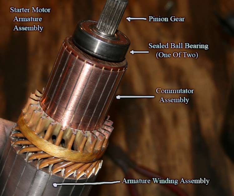
Finally, let's clean up the armature.
When you pulled the armature assembly from the motor housing, it should have come out firmly attached to the end plate. I figure the bearing's pressed into the end-plate. I tugged gently at it and figured I'd do best leaving it as is. If your's separated, just clean it up in there and stick it back together as you found it.
Where the brushes ride on the armature is called the commutator. It's design and layout relative to the poles of the armature, the brushes, and the fields of the housing involves a couple of bull elephants and some Chinese math. It's interesting (Do a Google).
Anyhoot, You'll most likely see where the brushes have been riding by the burn marks and such.
Folding some lightly used 400 grit sand paper into a 2" (approx) strip, we want to wrap the sand paper around the commutator so as to lightly polish the copper surface. DO NOT attempt to remove any big groves along the ends of the commutator and such. We just want to clean things up so as to aid the new brushes in seating. You may find it helpful to chuck the armature in your bench vise to do this. Clamp it on the large iron portion without crushing things. You just want to hold it while you sand.
Work your way around so as to have a uniform result.
OK, now take a small diameter pick and gently remove any boogers of carbon and stuff from in between the individual contacts of the commutator. DO NOT dig and gouge. We just want to remove the conductive carbon. Don't scratch against the edges of the grooves so as to disturb the copper.
Having cleared all the grooves, strike it once again lightly with the Scotchbrite as Trebor suggests to ensure a smooth round surface.
Now clean the stinky out of the assembly with compressed air, an old toothbrush, what ever. Just be sure all the remnants of the sand paper are gone from the entire assembly. Use a soft cloth to work in between the one exposed bearing and the commutator.
Make sure it's clean!
Now we're getting to the short rows.
Remember those two thin O-rings? Wipe them clean and reinstall them one on each end of the motor housing. There's a lip they rest on at the very edge of each housing end.
Opposite the brush end of the motor housing, you'll notice a small pin on the edge of the housing. It locates the motor end-plate to the motor housing.
Carefully holding everything, lower the motor housing and brush assembly down over the armature being careful of the brushes as the gear end of the armature come through. Just let it rest there.
Another set of hands will really help here as you've got to carefully move the brushes back in their holders so as to allow the commutator to pass through. Remember the brushes are fragile so keep the popping and snapping to a minimum. If you've got to do it by yourself like I did, move two of the brushes back in their holders and gently push down there on the housing. Hopefully, it'll sit sideways just enough for those two brushes to catch the edge of the commutator allowing you to push the other brushes back and have the housing sit on down.
Be patient, you can do it.
With the brushes now around the commutator, line up the pin on the housing with the hole in the end-plate. Slide them on together ensuring the O-ring is properly seated.
Spin the armature gently to ensure all is seated correctly with no weird binding. Keep in mind the brushes will now be riding on the commutator with full spring pressure and will drag if you will.
Now that the brush assembly is complete, we can reinstall it on the motor field housing. It's pretty much the reverse of disassembly.
Just like disassembly, place the motor housing with the motor power cable facing away from you. With the brush holder tang thing facing you, carefully slip the field connection bars through the brush holder assembly. Reconnect the two remaining brushes to the brush holder frame with the remaining Phillips head screws.
Once more, move the brushes in and out of their holders feeling for any weird binding.
That takes care of the brush mess.
Finally, let's clean up the armature.
When you pulled the armature assembly from the motor housing, it should have come out firmly attached to the end plate. I figure the bearing's pressed into the end-plate. I tugged gently at it and figured I'd do best leaving it as is. If your's separated, just clean it up in there and stick it back together as you found it.
Where the brushes ride on the armature is called the commutator. It's design and layout relative to the poles of the armature, the brushes, and the fields of the housing involves a couple of bull elephants and some Chinese math. It's interesting (Do a Google).
Anyhoot, You'll most likely see where the brushes have been riding by the burn marks and such.
Folding some lightly used 400 grit sand paper into a 2" (approx) strip, we want to wrap the sand paper around the commutator so as to lightly polish the copper surface. DO NOT attempt to remove any big groves along the ends of the commutator and such. We just want to clean things up so as to aid the new brushes in seating. You may find it helpful to chuck the armature in your bench vise to do this. Clamp it on the large iron portion without crushing things. You just want to hold it while you sand.
Work your way around so as to have a uniform result.
Originally Posted by Trebor
I have had almost 10 years of generator & alternator experiences behind me.
Don't use EMERY PAPER as a polishing/cleaning agent. Emery paper leaves behind a CONDUCTIVE residue. Check your Chiltons or Motors manuals on this topic. Instead always use sand paper - 320 or 400 followed by Scotchbrite as a final polishing agent.
Don't use EMERY PAPER as a polishing/cleaning agent. Emery paper leaves behind a CONDUCTIVE residue. Check your Chiltons or Motors manuals on this topic. Instead always use sand paper - 320 or 400 followed by Scotchbrite as a final polishing agent.
OK, now take a small diameter pick and gently remove any boogers of carbon and stuff from in between the individual contacts of the commutator. DO NOT dig and gouge. We just want to remove the conductive carbon. Don't scratch against the edges of the grooves so as to disturb the copper.
Having cleared all the grooves, strike it once again lightly with the Scotchbrite as Trebor suggests to ensure a smooth round surface.
Now clean the stinky out of the assembly with compressed air, an old toothbrush, what ever. Just be sure all the remnants of the sand paper are gone from the entire assembly. Use a soft cloth to work in between the one exposed bearing and the commutator.
Make sure it's clean!
Now we're getting to the short rows.
Remember those two thin O-rings? Wipe them clean and reinstall them one on each end of the motor housing. There's a lip they rest on at the very edge of each housing end.
Opposite the brush end of the motor housing, you'll notice a small pin on the edge of the housing. It locates the motor end-plate to the motor housing.
Carefully holding everything, lower the motor housing and brush assembly down over the armature being careful of the brushes as the gear end of the armature come through. Just let it rest there.
Another set of hands will really help here as you've got to carefully move the brushes back in their holders so as to allow the commutator to pass through. Remember the brushes are fragile so keep the popping and snapping to a minimum. If you've got to do it by yourself like I did, move two of the brushes back in their holders and gently push down there on the housing. Hopefully, it'll sit sideways just enough for those two brushes to catch the edge of the commutator allowing you to push the other brushes back and have the housing sit on down.
Be patient, you can do it.
With the brushes now around the commutator, line up the pin on the housing with the hole in the end-plate. Slide them on together ensuring the O-ring is properly seated.
Spin the armature gently to ensure all is seated correctly with no weird binding. Keep in mind the brushes will now be riding on the commutator with full spring pressure and will drag if you will.
The following users liked this post:
D2.5k (12-14-2017)
03-12-2007, 08:35 PM
#5
1st Generation Admin
Thread Starter
Now lay the motor behind the gear-case like it would go together.
Remember that tang on the brush holder? There's a corresponding slot just inside the gear-case where the motor plugs in. Find that slot.
Making sure the O-ring is properly in place, carefully slide the motor assembly into the gear-case with the tang going into it's slot of the gear-case.

Seeing that things are squarely seated, reinstall the two long bolts and snug them up.
Reconnect the motors power cable to its solenoid bolt with the remaining washer and thin nut you had from the solenoid rebuild. Replace the cables rubber boot nice'n purdy.
Ho'tay Panky!
Assuring the truck's still safe to climb under, reinstall the starter into the engine just like you took it out. Tighten the starter mounting bolts to 50ft.lbs.
Reattach the solenoids start wire and torque the nut to 55in.lbs. Reattach the battery cable to the solenoid and torque the nut to 90in.lbs.
Reinstall the crankcase vent tube.
Finally, reconnect the negative battery cable to the battery. (At this point, no big sparks is a good thing. Mine did spark a little, but nothing that made me second guess the starter deal).
Making sure all your tools are accounted for and out of the way, look one more time to see that all is where it should be.
Now start your truck and drive carefully.
Here's hoping this helps you sort out an otherwise aggravating starter.
NOTE: The instruction I've gotten to date doesn't include the proper bolt torque figures of the starter assembly itself. I think those involving the two solenoid electrical bolts would be the more critical being that you want them secure WITHOUT busting the phenolic insulators. Elsewhere: "Goodntight" should suffice.
I'll most likely be editing this over the next 24 hours to include anything you good folks might contribute: Questions, Concerns, Rude Remarks . . . .
Remember that tang on the brush holder? There's a corresponding slot just inside the gear-case where the motor plugs in. Find that slot.
Making sure the O-ring is properly in place, carefully slide the motor assembly into the gear-case with the tang going into it's slot of the gear-case.
Seeing that things are squarely seated, reinstall the two long bolts and snug them up.
Reconnect the motors power cable to its solenoid bolt with the remaining washer and thin nut you had from the solenoid rebuild. Replace the cables rubber boot nice'n purdy.
Ho'tay Panky!
Assuring the truck's still safe to climb under, reinstall the starter into the engine just like you took it out. Tighten the starter mounting bolts to 50ft.lbs.
Reattach the solenoids start wire and torque the nut to 55in.lbs. Reattach the battery cable to the solenoid and torque the nut to 90in.lbs.
Reinstall the crankcase vent tube.
Finally, reconnect the negative battery cable to the battery. (At this point, no big sparks is a good thing.
Mine did spark a little, but nothing that made me second guess the starter deal).Making sure all your tools are accounted for and out of the way, look one more time to see that all is where it should be.
Now start your truck and drive carefully.
Here's hoping this helps you sort out an otherwise aggravating starter.
NOTE: The instruction I've gotten to date doesn't include the proper bolt torque figures of the starter assembly itself. I think those involving the two solenoid electrical bolts would be the more critical being that you want them secure WITHOUT busting the phenolic insulators. Elsewhere: "Goodntight" should suffice.
I'll most likely be editing this over the next 24 hours to include anything you good folks might contribute: Questions, Concerns, Rude Remarks . . . .
The following 3 users liked this post by BC847:
Trending Topics
03-12-2007, 09:43 PM
#9
Registered User
Join Date: Nov 2006
Location: Pearland, TX
Posts: 299
Likes: 0
Received 0 Likes
on
0 Posts
BC847, Awesome POST!!! I have never read a post that more deserved to be a STICKY, I mean never.
Well said and well posted, pictures were spot on!
Impressed...
Hay
Well said and well posted, pictures were spot on!
Impressed...
Hay
03-12-2007, 09:55 PM
#10
Registered User
 03-13-2007, 12:02 AM
#11
1st Generation Admin
Thread Starter
Thanks for the kind words folks.
This was kinda fun as I got to work out my new Cannon 400D digital SLR camera (the other camera was stolen ). Unfortunately, in preparing the images for this thread, I had to back off on the image quality big-time so as not to hammer the 56k crowd among us.
Got a new rear disc-brake conversion kit arriving supposedly this Friday. That ought to be a hoot!
In the mean time, last week, the truck briefly presented with the no speedo/alternator syndrome. Tonight it's doing it constantly. Just to be different, I have overdrive. Geezzzzz!
This was kinda fun as I got to work out my new Cannon 400D digital SLR camera (the other camera was stolen
). Unfortunately, in preparing the images for this thread, I had to back off on the image quality big-time so as not to hammer the 56k crowd among us. Got a new rear disc-brake conversion kit arriving supposedly this Friday. That ought to be a hoot!
In the mean time, last week, the truck briefly presented with the no speedo/alternator syndrome. Tonight it's doing it constantly. Just to be different, I have overdrive. Geezzzzz!
 03-13-2007, 04:36 PM
#15
1st Generation Admin
Thread Starter
Fellow DTR member broncobilly posted recently about rebuilding his mess using these folks parts ~ http://www.fostertruck.com/dodge/
I went with them as well being that I was intrigued with the over-sized contacts with Larry's kit. Since purchasing said kit, others have posted with alternate sources (naturally, some less expensive.
Here's Billy's thread ~ https://www.dieseltruckresource.com/...d.php?t=139207
Hope this helps.
I went with them as well being that I was intrigued with the over-sized contacts with Larry's kit. Since purchasing said kit, others have posted with alternate sources (naturally, some less expensive.
Here's Billy's thread ~ https://www.dieseltruckresource.com/...d.php?t=139207
Hope this helps.