Robert Bosch VE Pump Operation
 02-03-2009, 02:42 PM
#1
Registered User
Thread Starter
Robert Bosch VE Pump Operation
hey guys. i was digging through stuff and found my fuel injection handbook from my diesel class. thought i'd create little write up with the info from the book for any of you that might be interested in reading about our VE's.
Overview
The injection pump is a single-plunger mechanical pump which meters and distributes fuel to the injectors in the correct firing order. The pump is driven by the camshaft spur belt or gear at one-half crankshaft speed. All moving parts inside the pump are lubricated by diesel fuel, so the pump is maintenance-free; diesel pumps operate reliably for a long time if clean fuel is used.
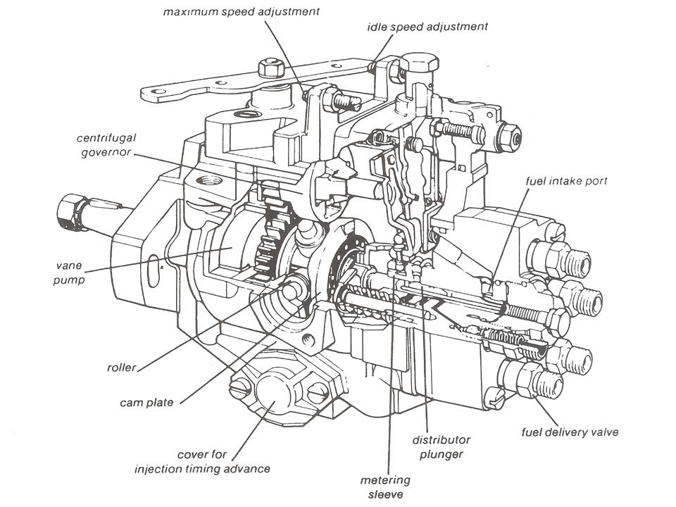
Idle speed, maximum speed, and injection timing can be adjusted with workshop equipment; the stop solenoid can be replaced, the fuel delivery valve body can be replaced, but any internal problem means replacement of the pump.
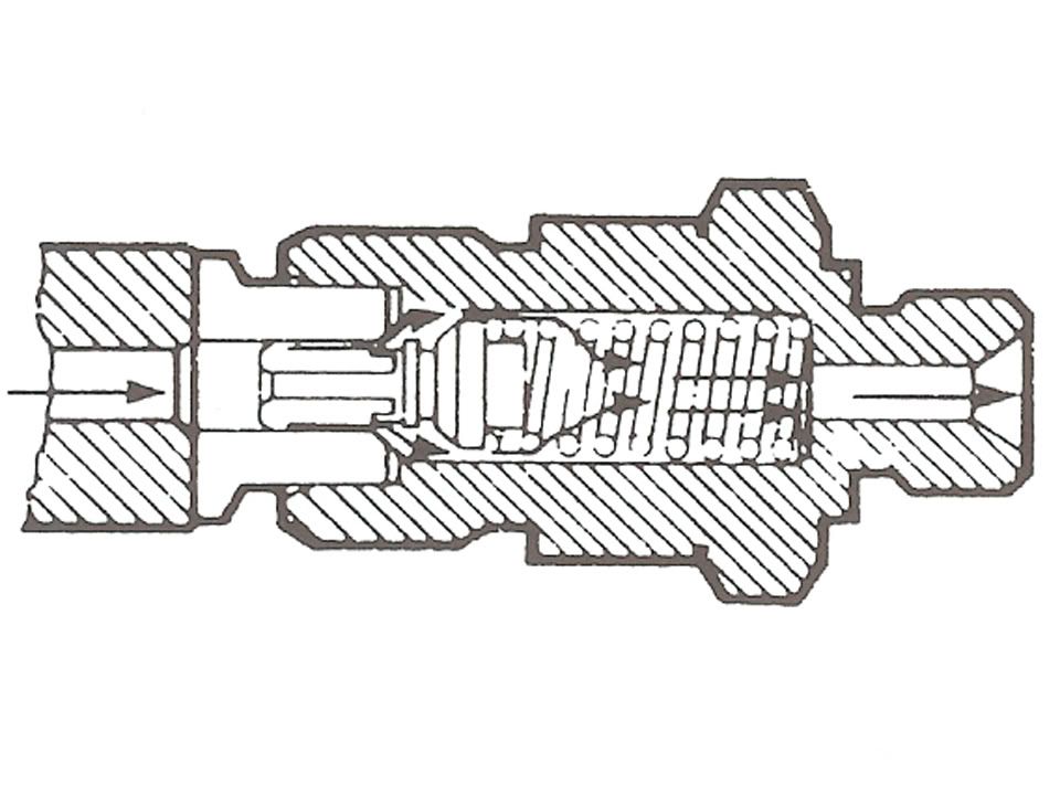
Fuel Delivery Valves
The fuel delivery valves on the injection pump help ensure that the injector will close quickly at the end of each injection. The injectors must close quickly in order to prevent fuel "dribble" which can cause pre-ignition and high exhaust emissions.
At the start of injection the delivery valve is lifted off of its seat and pressurized fuel flows to the injector:
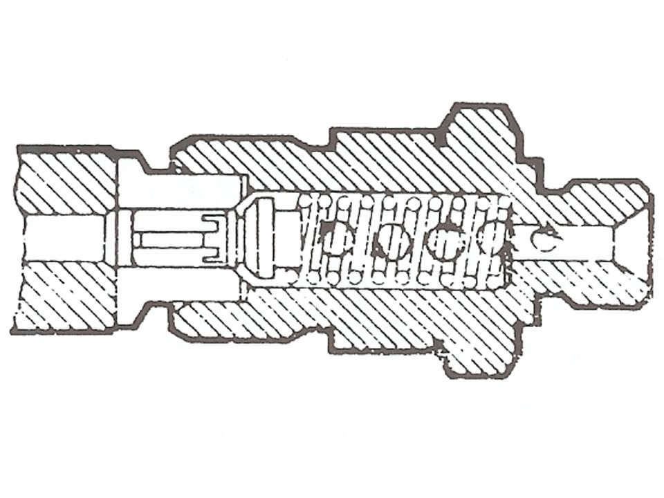
At the end of injection the delivery valve moves to the closed position. A column of fuel is now trapped in the injection line:
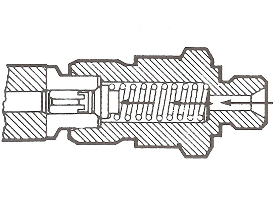
The force of the spring will push the valve back further onto its seat and the trapped column of fuel now expands. The sudden drop in pressure caused by the expanding fuel, allows the injector to snap shut and eliminate and fuel "dribble":
Vane Pump
The rotary-vane pump inside the injection pump draws fuel through the filter from the tank and supplies it to the distributor plunger.
The vane pump rotor is driven by the engine camshaft spur belt or gear. As the rotor spins, centrifugal force holds the vanes against the walls of the pressure chamber. The off-center or eccentric layout of the rotor and pressure chamber "squeezes" fuel trapped between the vanes and forces it out the delivery port.

Vane pump delivery pressure is between 3-7 bar depending on the engine speed and is controlled by the regulating valve.
Vane pump fuel pressure lubricates moving parts in the rest of the pump, supplies fuel to the distributor plunger for the injectors, and controls injection timing advance mechanism.
Injection pump manufacturers use a special test "bench" to set and check internal pump pressures. The vane pump and distributor plunger injection pressures cannot be checked easily with normal workshop equipment.
If clean fuel is used, diesel injection pumps operate reliably for a long time. Diesel pumps should not be disassembled or "adjusted." Normal shop work consists only of troubleshooting to determine whether a pump might need replacement.
Injection & Distribution
The injection pump driveshaft turns the vane pump, distributor plunger, and cam plate as a unit.
Springs hold the cam plate and distributor plunger against stationary rollers - in this way, the plunger also moves back and forth as it turns:

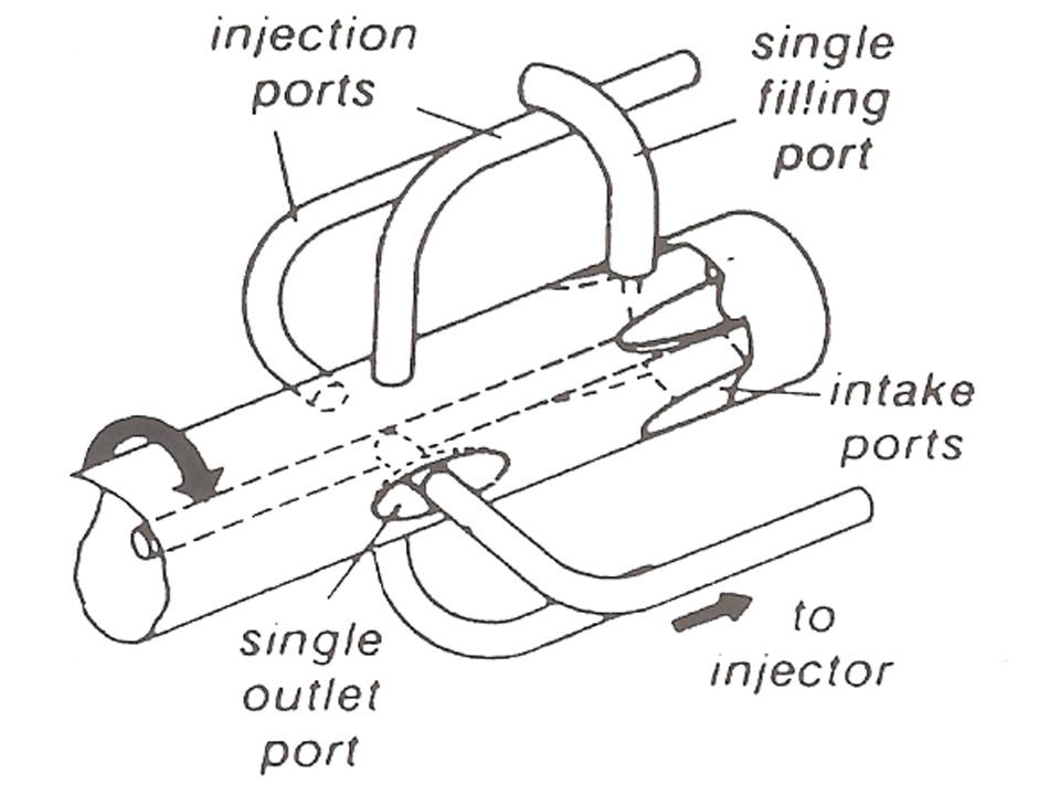
Whenever an intake port in the plunger is in line with the filling port in the pump body, fuel from the vane pump fills the pressure chamber.
As the plunger turns, the intake port is covered up so that fuel is trapped in the pressure chamber. Now, the cam plate and rollers push the plunger and pressurize the fuel to about 1800 psi.:
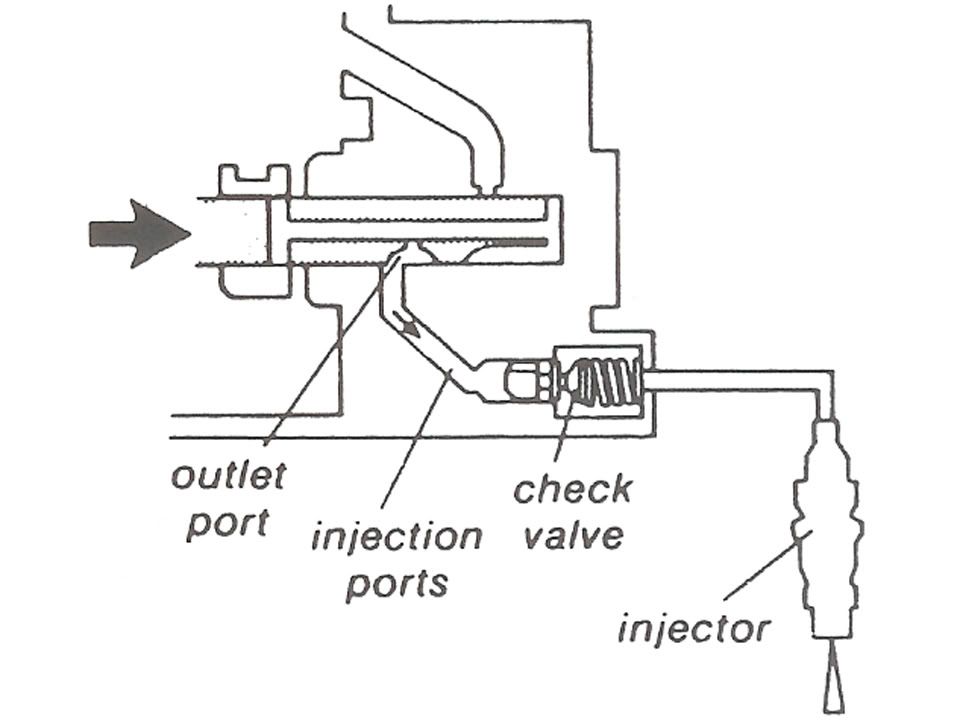
As the plunger continues to turn, the outlet port in the plunger lines up with the injection passage in the pump body, opening the check valve and supplying high-pressure fuel to the injector.
The injection ports in the pump are arranged so the injectors receive fuel in the cylinder firing sequence:
Metering Fuel
The amount of fuel injected is controlled by changing the injection cut-off point according to engine speed and load conditions.
The injection cut-off point is controlled by the position of a metering sleeve on the distributor plunger. The metering sleeve usually covers a relief port in the plunger. Uncovering the relief port stops injection.
The position of the metering sleeve is controlled by a linkage connected to a centrifugal governor and also the accelerator pedal.
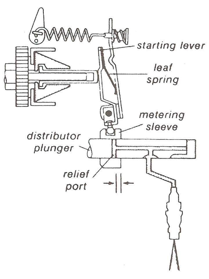
Metering Fuel - Starting
When the engine is not running, the leaf spring presses the starting lever to the left so that the metering sleeve moves to the right.
The distributor plunger must move further before the relief port is exposed. Injection lasts longer so that more fuel is supplied during starting:
Overview
The injection pump is a single-plunger mechanical pump which meters and distributes fuel to the injectors in the correct firing order. The pump is driven by the camshaft spur belt or gear at one-half crankshaft speed. All moving parts inside the pump are lubricated by diesel fuel, so the pump is maintenance-free; diesel pumps operate reliably for a long time if clean fuel is used.
Idle speed, maximum speed, and injection timing can be adjusted with workshop equipment; the stop solenoid can be replaced, the fuel delivery valve body can be replaced, but any internal problem means replacement of the pump.
Fuel Delivery Valves
The fuel delivery valves on the injection pump help ensure that the injector will close quickly at the end of each injection. The injectors must close quickly in order to prevent fuel "dribble" which can cause pre-ignition and high exhaust emissions.
At the start of injection the delivery valve is lifted off of its seat and pressurized fuel flows to the injector:
At the end of injection the delivery valve moves to the closed position. A column of fuel is now trapped in the injection line:
The force of the spring will push the valve back further onto its seat and the trapped column of fuel now expands. The sudden drop in pressure caused by the expanding fuel, allows the injector to snap shut and eliminate and fuel "dribble":
Vane Pump
The rotary-vane pump inside the injection pump draws fuel through the filter from the tank and supplies it to the distributor plunger.
The vane pump rotor is driven by the engine camshaft spur belt or gear. As the rotor spins, centrifugal force holds the vanes against the walls of the pressure chamber. The off-center or eccentric layout of the rotor and pressure chamber "squeezes" fuel trapped between the vanes and forces it out the delivery port.
Vane pump delivery pressure is between 3-7 bar depending on the engine speed and is controlled by the regulating valve.
Vane pump fuel pressure lubricates moving parts in the rest of the pump, supplies fuel to the distributor plunger for the injectors, and controls injection timing advance mechanism.
Injection pump manufacturers use a special test "bench" to set and check internal pump pressures. The vane pump and distributor plunger injection pressures cannot be checked easily with normal workshop equipment.
If clean fuel is used, diesel injection pumps operate reliably for a long time. Diesel pumps should not be disassembled or "adjusted." Normal shop work consists only of troubleshooting to determine whether a pump might need replacement.
Injection & Distribution
The injection pump driveshaft turns the vane pump, distributor plunger, and cam plate as a unit.
Springs hold the cam plate and distributor plunger against stationary rollers - in this way, the plunger also moves back and forth as it turns:
Whenever an intake port in the plunger is in line with the filling port in the pump body, fuel from the vane pump fills the pressure chamber.
As the plunger turns, the intake port is covered up so that fuel is trapped in the pressure chamber. Now, the cam plate and rollers push the plunger and pressurize the fuel to about 1800 psi.:
As the plunger continues to turn, the outlet port in the plunger lines up with the injection passage in the pump body, opening the check valve and supplying high-pressure fuel to the injector.
The injection ports in the pump are arranged so the injectors receive fuel in the cylinder firing sequence:
Metering Fuel
The amount of fuel injected is controlled by changing the injection cut-off point according to engine speed and load conditions.
The injection cut-off point is controlled by the position of a metering sleeve on the distributor plunger. The metering sleeve usually covers a relief port in the plunger. Uncovering the relief port stops injection.
The position of the metering sleeve is controlled by a linkage connected to a centrifugal governor and also the accelerator pedal.
Metering Fuel - Starting
When the engine is not running, the leaf spring presses the starting lever to the left so that the metering sleeve moves to the right.
The distributor plunger must move further before the relief port is exposed. Injection lasts longer so that more fuel is supplied during starting:
 02-03-2009, 02:44 PM
#2
Registered User
Thread Starter
Robert Bosch VE Pump Operation part 2
Metering Fuel - Idle
At idle speed, the weights in the centrifugal governor are partly expanded so that governor sleeve move to the right. The starting lever is pushed against the control lever so that the metering sleeve moves to the left.
The distributor plunger now moves a shorts distance before the relief port is uncovered. Injection lasts a short time fo that a small amount of fuel is supplied at idle:
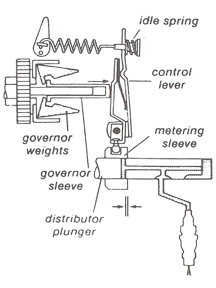
The injection pump automatically compensates for effects of temperature and load changes at idle. When idle speed begins to drop, the centrifugal governor weights and the governor sleeve retract; the idle spring then pushes the metering sleeve to the right, increasing the amount of fuel to correct the idle speed.
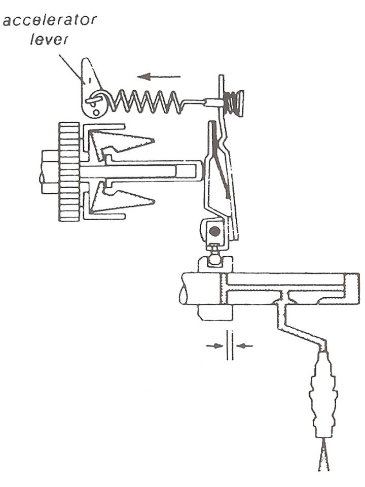
Metering Fuel - Acceleration
During acceleration, the control lever is pulled to the left by the linkage from the accelerator pedal.
The metering sleeve is moved to the right so that more fuel is injected before the relief port in uncovered. Engine speed increases until the movemnt of the governor "neutralizes" the effect of the pedal linkage:
Metering Fuel - Maximum Speed
With the pedal linkage at "full load," engine speed increases to about 5400 rpm. At this point, the governor is spinning with enough centrifugal force for the governor sleeve to "stretch" the governor spring and force the control lever to the right.
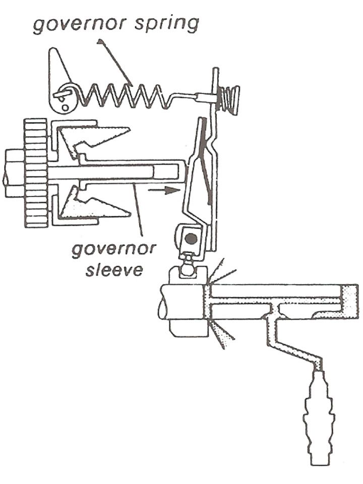
The metering sleeve moves far enough to the left to uncover the relief port at the beginning of the distributor plunger stroke. There is no pressure for injection until engine speed drops and the metering sleeve moves to the right again.
This provision acts as a speed limiter and is designed to react slowly enough so that engine performance simply "flattens out" at the top limit.
Injection Timing Advance
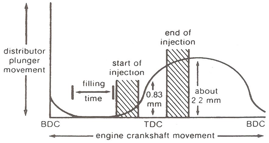
Near the end of each compression stroke, diesel fuel is injected directly into the combustion chamber. Injection must continue well past piston TDC in order to burn the necessary amount of fuel to provide engine power.
As engine speed increases, stroke timing becomes shorter and injection timing becomes longer. Burning must begin sooner to ensure that peak combustion pressures still occur at the most efficient point after TDC.
Diesel injection timing is advanced by a hydraulic piston in the injection pump:
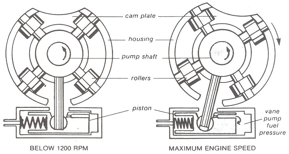
As engine speed increases, fuel pressure from the vane pump also increases. Vane pump pressure pushes the injection advance piston to the left against the spring so that the roller housing turns slightly.
Since the cam plate is turning in the opposite direction, the "ramps" on the cam plate engage the roller sooner whenever the injection advance piston moves to the left. This means that the distributor plunger beings injection sooner.
The injection timing advance piston is located in the bottom of the injection pump body:
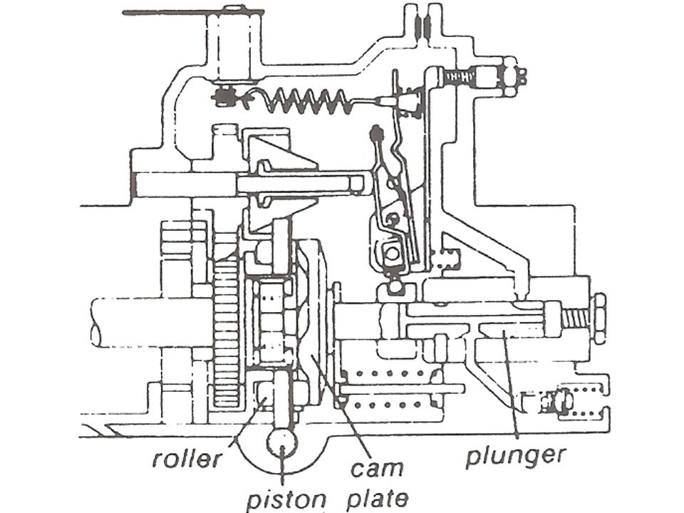
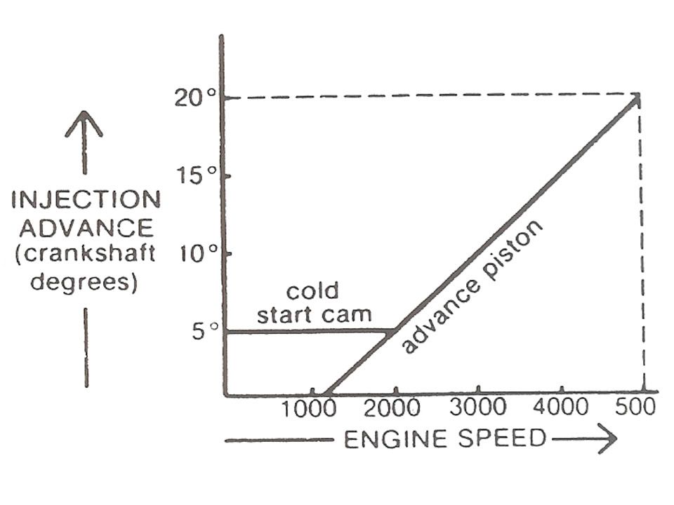
The only cold start and warm-up device necessary for the diesel fuel system is a control which advances injection timing at idle and during low speed running.
A lever turns a cam which pushes the hydraulic piston to the left. This advances injection time about 5 degrees.

This injection advance provides more time for the fuel to burn, which improves performance and prevents smoking during cold starts and warm-up.
The cold start cam does not advance the complete range of injection timing. Above 2200 rpm, the piston operates normally and does not contact the cam:
Injection Timing
Since diesel fuel ignites in the hot compressed air as soon as injection begins, injection timing is as important as gasoline engine spark timing.
The actual moment of injection cannot be checked easily because it is affected not only by the injection advance mechanism but also by the exact opening pressure of each injector.
Well that's what i've got guys. I hope this helps you will any problems you may have or maybe just give you a good knowledge base so you can confuse all your friends

I've also got all designation codes for the pumps and injectors that i'll scan just for even more knowledge. Enjoy!
At idle speed, the weights in the centrifugal governor are partly expanded so that governor sleeve move to the right. The starting lever is pushed against the control lever so that the metering sleeve moves to the left.
The distributor plunger now moves a shorts distance before the relief port is uncovered. Injection lasts a short time fo that a small amount of fuel is supplied at idle:
The injection pump automatically compensates for effects of temperature and load changes at idle. When idle speed begins to drop, the centrifugal governor weights and the governor sleeve retract; the idle spring then pushes the metering sleeve to the right, increasing the amount of fuel to correct the idle speed.
Metering Fuel - Acceleration
During acceleration, the control lever is pulled to the left by the linkage from the accelerator pedal.
The metering sleeve is moved to the right so that more fuel is injected before the relief port in uncovered. Engine speed increases until the movemnt of the governor "neutralizes" the effect of the pedal linkage:
Metering Fuel - Maximum Speed
With the pedal linkage at "full load," engine speed increases to about 5400 rpm. At this point, the governor is spinning with enough centrifugal force for the governor sleeve to "stretch" the governor spring and force the control lever to the right.
The metering sleeve moves far enough to the left to uncover the relief port at the beginning of the distributor plunger stroke. There is no pressure for injection until engine speed drops and the metering sleeve moves to the right again.
This provision acts as a speed limiter and is designed to react slowly enough so that engine performance simply "flattens out" at the top limit.
Injection Timing Advance
Near the end of each compression stroke, diesel fuel is injected directly into the combustion chamber. Injection must continue well past piston TDC in order to burn the necessary amount of fuel to provide engine power.
As engine speed increases, stroke timing becomes shorter and injection timing becomes longer. Burning must begin sooner to ensure that peak combustion pressures still occur at the most efficient point after TDC.
Diesel injection timing is advanced by a hydraulic piston in the injection pump:
As engine speed increases, fuel pressure from the vane pump also increases. Vane pump pressure pushes the injection advance piston to the left against the spring so that the roller housing turns slightly.
Since the cam plate is turning in the opposite direction, the "ramps" on the cam plate engage the roller sooner whenever the injection advance piston moves to the left. This means that the distributor plunger beings injection sooner.
The injection timing advance piston is located in the bottom of the injection pump body:
The only cold start and warm-up device necessary for the diesel fuel system is a control which advances injection timing at idle and during low speed running.
A lever turns a cam which pushes the hydraulic piston to the left. This advances injection time about 5 degrees.
This injection advance provides more time for the fuel to burn, which improves performance and prevents smoking during cold starts and warm-up.
The cold start cam does not advance the complete range of injection timing. Above 2200 rpm, the piston operates normally and does not contact the cam:
Injection Timing
Since diesel fuel ignites in the hot compressed air as soon as injection begins, injection timing is as important as gasoline engine spark timing.
The actual moment of injection cannot be checked easily because it is affected not only by the injection advance mechanism but also by the exact opening pressure of each injector.
Well that's what i've got guys. I hope this helps you will any problems you may have or maybe just give you a good knowledge base so you can confuse all your friends
I've also got all designation codes for the pumps and injectors that i'll scan just for even more knowledge. Enjoy!
02-03-2009, 03:03 PM
#3
Registered User
Join Date: Jul 2007
Location: Hurricane, Utah
Posts: 166
Likes: 0
Received 0 Likes
on
0 Posts
Wow. I'm not really I understood what I just saw. Better go back for another read. Thanks for the detailed info. I'm sure this will benefit many on these boards. Thanks!
02-03-2009, 03:26 PM
#4
Administrator

This is some good information; Last week I had my pump down to the rollers and cam plate when I replaced most of the seals on it.
At first I reassembled it the way I thought it would go together then I used the exploded diagram and I found I was right.
Although the VE is a precision piece of machinery it is amazingly simple once you know how it works.
The tricky part is the governor because if it binds or fails your engine could instantly become a 1000 pounds of junk metal.
I used to work on Detroit�s, Cummins, Perkins and anytime I worked on the PT pump, injectors of fuel rack I would check and recheck my work before I started the engine, there was no room for a mistake.
If you have ever been near a runaway you will never forget it, it leaves a very lasting impression.
Jim

Trending Topics
02-04-2009, 12:42 AM
#8
Registered User
Thread Starter
Wow!! I made it into the sticky thread?? Sweet!
I bought the book at my school through the book store. it's simply titled "Diesel Technology: Fuel Injection Handbook." All the information is provided by Robert Bosch Corporation. It has a total of 8 units. it covers nozzles and holders, injection principles, multiple-unit injection pump systems, detroit diesel needle valve fuel injectors, operation and instruction manual for the stanadyne or roosa master model db2 system, cummins p.t. system, bosch ve pump operation, bosch designation codes for diesel products, and trouble shooting charts for fuel systems.
This is a great program to get involved in at Golden West College in Huntington Beach, California. If any of you live in the area and are interested, I recommend the classes. Dave Walker is the instructor and, in my opinion, is the best for the class. He was in the diesel industry and worked on everything you could possibly think of for 30+ years. Very knowledgeable man!
02-04-2009, 10:03 PM
#10
Registered User
Hey thanks! Wow would have never though that a college in Huntington Beach would have a diesel course. I have family that live there, so I visit from time to time.


Thread
Thread Starter
Forum
Replies
Last Post
truckbouy2
3rd Gen Engine and Drivetrain -> 2003-2007
10
03-29-2008 10:48 AM