The motor Build thread.
 01-23-2014, 10:53 PM
#1
Registered User
Thread Starter
The motor Build thread.
Remember a long while back I was talking about my shiny new parts. Aka my ctech head and other goodies?
Well it's all finally going to be assembled!
First off, these are the end game parts. It's going in the Ford in my sig.
New 0.040" over marine pistons
Reusing my 181/210 Hamilton cam with retainer
Reusing my a1 head studs.
New ctech head. P&p, O - rings, oversized/cut valves. Updated valve stem steals
New 165# Hamilton springs & retainers
Hamilton pushrods
New fluidampr
New arp 14mm main studs
New arp L19 rod bolts
Gasket matched my existing ats manifold and aurora 4000.
Reusing my manifold and turbo blankets
Will be wrapping the downpipe.
New bosch marine 5 hole 80lpm injectors on order.
Custom afc work
Plus what's in my sig and a few other things like a pusher pump.
Anyways... This is how I spent my birthday today...
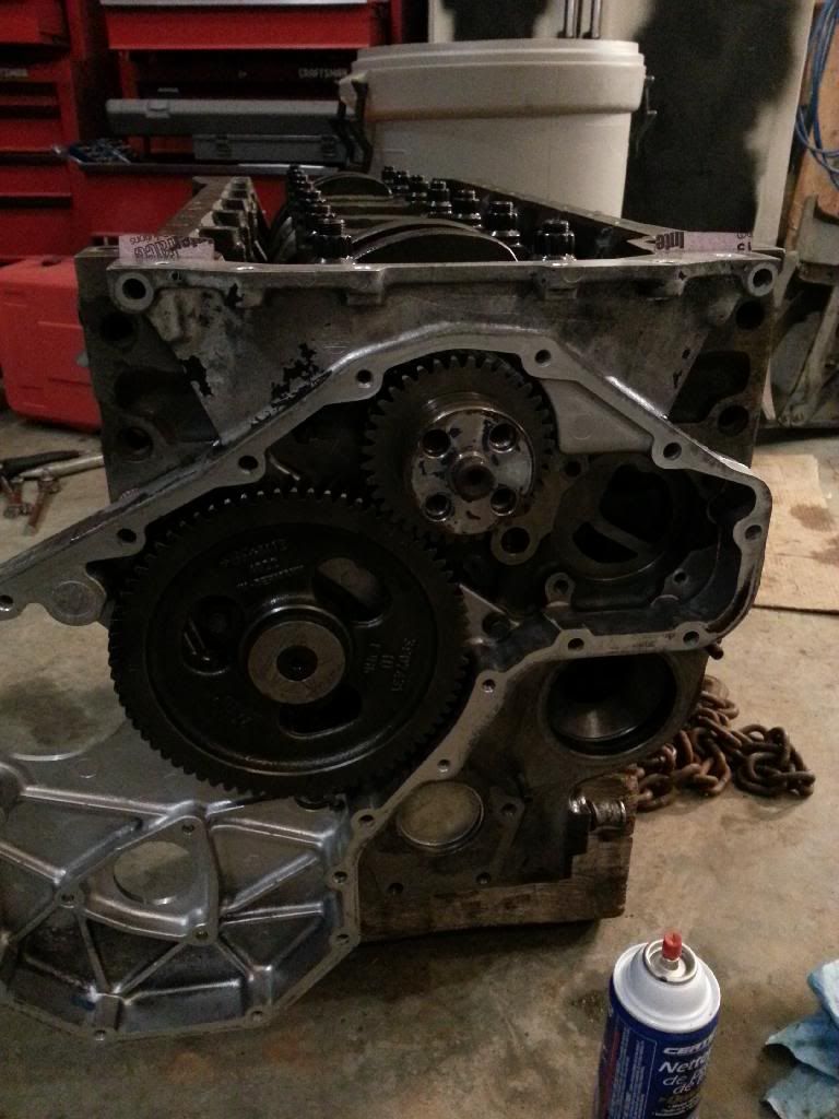
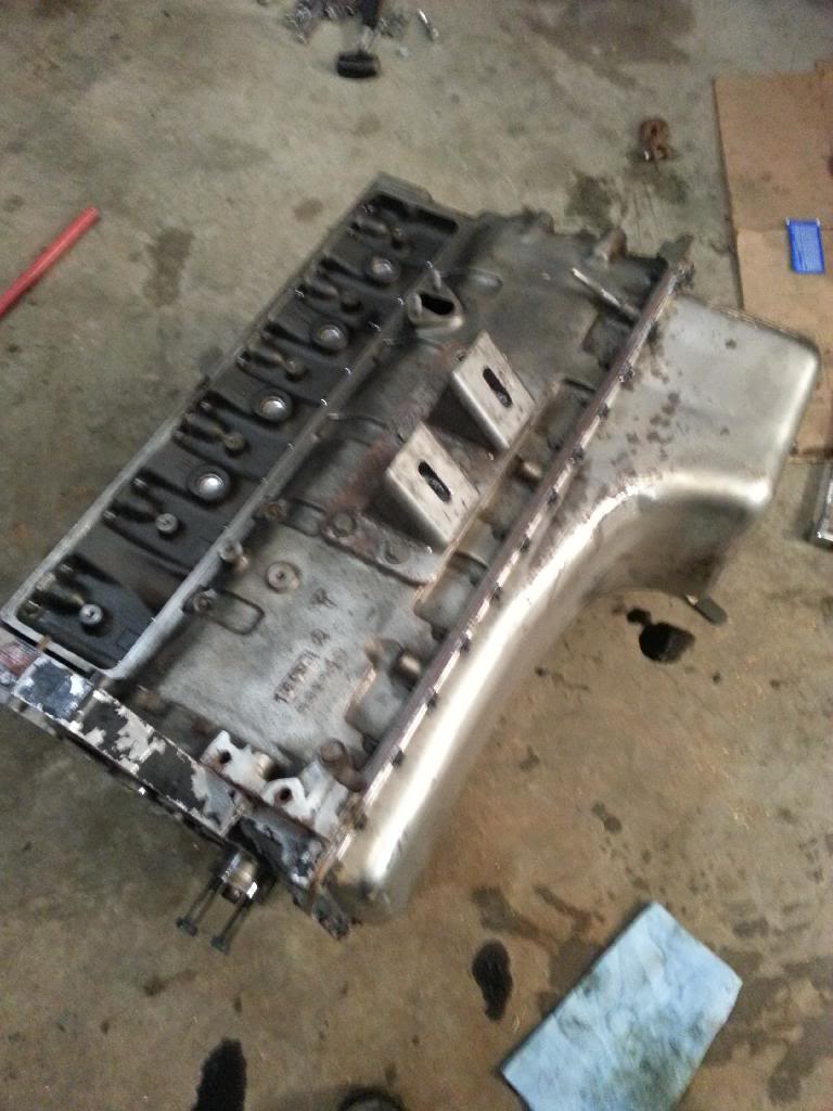
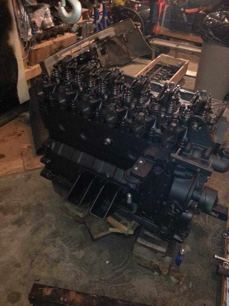
Got the block back today from being line honed, bored 0.040" over and cleaned with a new cam bushing. Got the rods with new wrist pin bushings back as well. Beyond getting everything home I didn't manage to get a lot done.
Just got the crank and cam in and all locked down with the new main studs. Those suckers torque down to 175ft/lbs! I had to fight with the stupid engine stand for a while. Ended up having to take the block and set it upside down on some blocks to actually get the crank in. So basically long story short I can't use the engine stand... The rest of the project will be interesting without it. Tomorrow hopefully I can get the pistons together and in along with the rear main. Maybe assemble the head as well, time permitting of course. It's not much to look at yet... Good way to spend a birthday to be honest. It was difficult to stop for the night but I had to pick the girlfriend up from her internship at 10 so....
After tomorrow I won't have any time until Monday to work on it. I'll be far too busy with working during the day and birthday celebrations (aka going snowboarding and getting drunk) sat. night and hockey Sunday night.
Couple pictures I took for progress sake.
Sent from Tapatalk 4 via a Galaxy S3
Well it's all finally going to be assembled!
First off, these are the end game parts. It's going in the Ford in my sig.
New 0.040" over marine pistons
Reusing my 181/210 Hamilton cam with retainer
Reusing my a1 head studs.
New ctech head. P&p, O - rings, oversized/cut valves. Updated valve stem steals
New 165# Hamilton springs & retainers
Hamilton pushrods
New fluidampr
New arp 14mm main studs
New arp L19 rod bolts
Gasket matched my existing ats manifold and aurora 4000.
Reusing my manifold and turbo blankets
Will be wrapping the downpipe.
New bosch marine 5 hole 80lpm injectors on order.
Custom afc work
Plus what's in my sig and a few other things like a pusher pump.
Anyways... This is how I spent my birthday today...
Got the block back today from being line honed, bored 0.040" over and cleaned with a new cam bushing. Got the rods with new wrist pin bushings back as well. Beyond getting everything home I didn't manage to get a lot done.
Just got the crank and cam in and all locked down with the new main studs. Those suckers torque down to 175ft/lbs! I had to fight with the stupid engine stand for a while. Ended up having to take the block and set it upside down on some blocks to actually get the crank in. So basically long story short I can't use the engine stand... The rest of the project will be interesting without it. Tomorrow hopefully I can get the pistons together and in along with the rear main. Maybe assemble the head as well, time permitting of course. It's not much to look at yet... Good way to spend a birthday to be honest. It was difficult to stop for the night but I had to pick the girlfriend up from her internship at 10 so....
After tomorrow I won't have any time until Monday to work on it. I'll be far too busy with working during the day and birthday celebrations (aka going snowboarding and getting drunk) sat. night and hockey Sunday night.
Couple pictures I took for progress sake.
Sent from Tapatalk 4 via a Galaxy S3

 01-24-2014, 07:39 AM
#4
Registered User
Thread Starter
You can take the dowels out butI it's easier to keep them in as they centre the timing case properly.
They are actually really hard to remove unless it's on the verge of falling out.
Sent from Tapatalk 4 via a Galaxy S3
They are actually really hard to remove unless it's on the verge of falling out.
Sent from Tapatalk 4 via a Galaxy S3
01-24-2014, 08:09 AM
#5
Registered User

What piston cooling nozzles are you using? I only ask because a couple of mine came out, and I am not sure what the current best practices are for them . . .
Thanks,
Alec
Thanks,
Alec
01-24-2014, 09:48 AM
#7
Registered User
Thread Starter
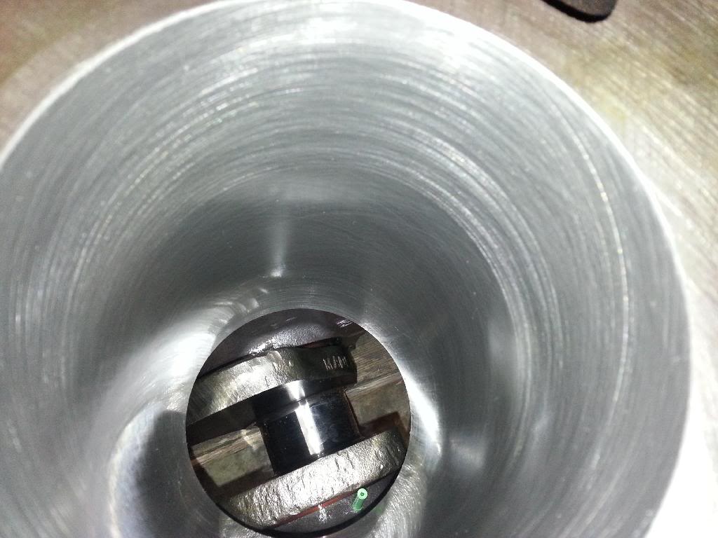
Mine are green. And the same diameter the whole length. I can take a picture of them later tonight.
You are taking them out and putting them in properly right? May sound like a dumb question but I just can't see how they would come out
Sent from Tapatalk 4 via a Galaxy S3
You are taking them out and putting them in properly right? May sound like a dumb question but I just can't see how they would come out
Sent from Tapatalk 4 via a Galaxy S3
Trending Topics
01-24-2014, 07:53 PM
#8
Registered User
 01-24-2014, 10:32 PM
#9
Registered User
Thread Starter
Ya... That would be nice!
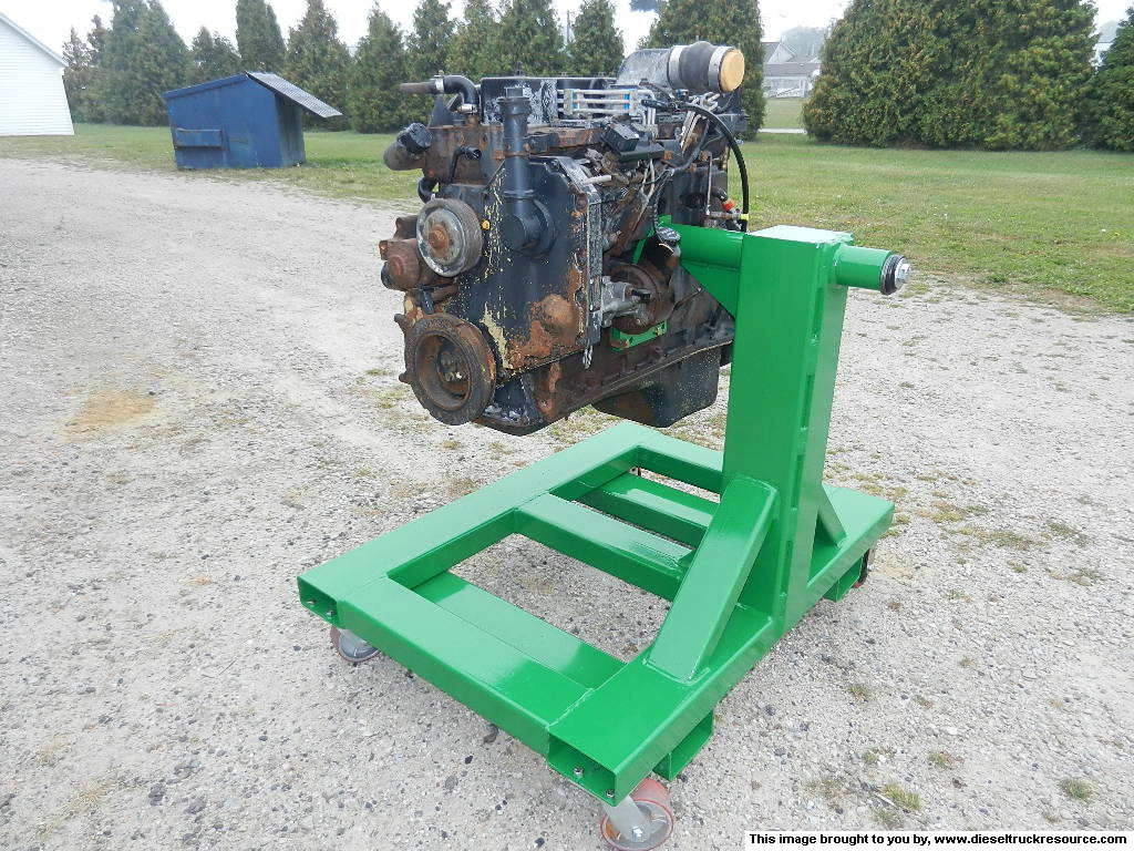
The stand I have is rated for 1000lbs but I begins to sag with just the crank and cam in. No injector pump. No manifold or turbo. No head...
I can't use it because where it mounts at the back of the block interferes with the crankshaft/rear seal housing.
Sent from Tapatalk 4 via a Galaxy S3
The stand I have is rated for 1000lbs but I begins to sag with just the crank and cam in. No injector pump. No manifold or turbo. No head...
I can't use it because where it mounts at the back of the block interferes with the crankshaft/rear seal housing.
Sent from Tapatalk 4 via a Galaxy S3
01-24-2014, 11:35 PM
#10
Registered User
Thread Starter
Oh hey Jim I didn't even notice you're in Ontario too. Go figure. Although you're probably in Southern Ontario... bah! haha
Ok as for tonights work...
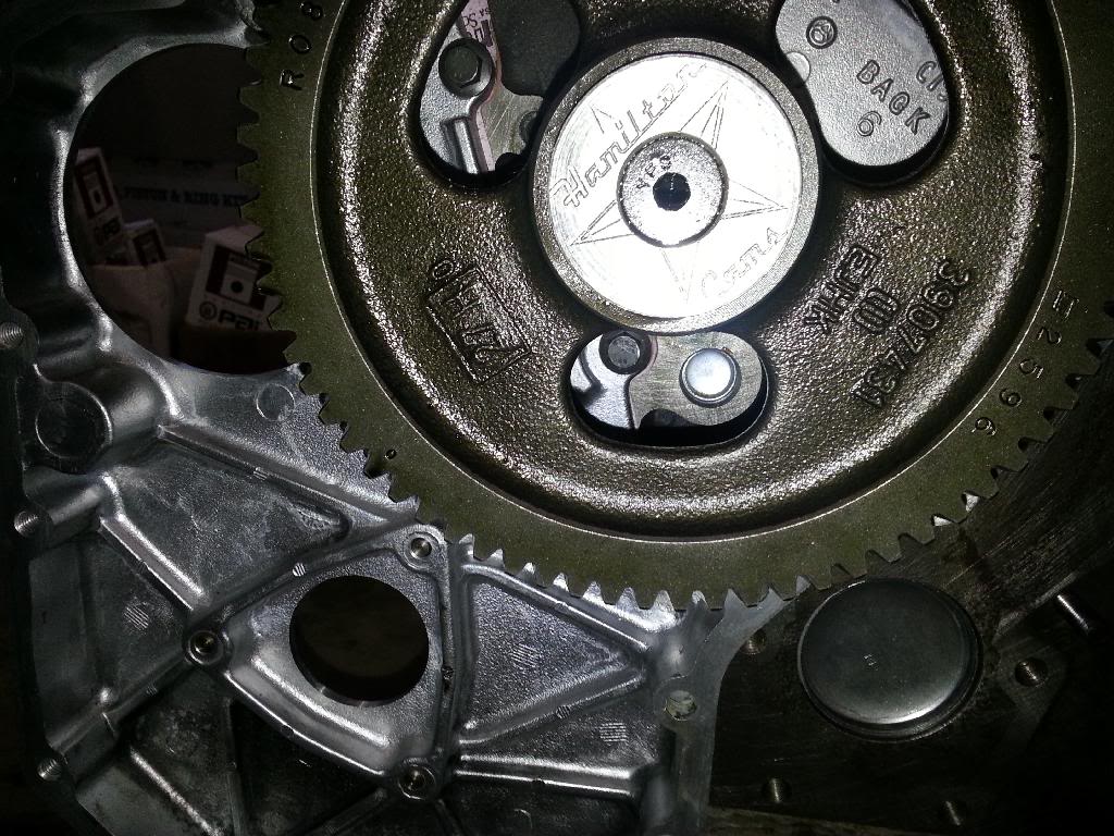
First order of business was this little guy.
And by this little guy I mean the oil plug behind the cam. The guy at the machine shop that did the block work called me and told me he noticed that that particular plug was MIA. I said I didn't remove it, and he said he didn't remove it. Apparently at some point or another it got blown out? Come to think of it I sort of remember noticing a plug in the bottom of the pan when I disassembled the motor. That said, I'm not totally sure of that. And my oil pressure was fine when I took it apart so who knows...
anyways, I had to take out the cam retainer and pull the cam out a few inches to get at it properly. Fortunately for me I actually already had the plug because 2 years ago when I did the motor I bought the freeze plug kit but only did some of the plugs. Not that one though. after I got it in I got the cam back in place.
Second was getting the rear main seal and seal housing on. 7ft lbs on the 6 little bolts holding it in and that was done (no picture apparently)
Third order of business was installing the oil pump.
Then I had to some how roll the motor so I can deal with the pistons. I ended up dropping/rolling the whole **** thing right on to the concrete floor. I got lucky though, nothing was damaged
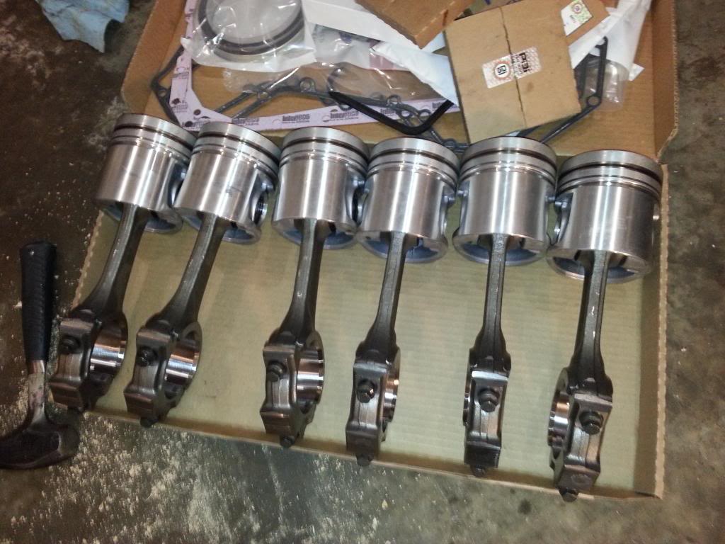
Next order of business was getting the pistons on the connecting rods. New wrist pin bushings were put in by the shop.
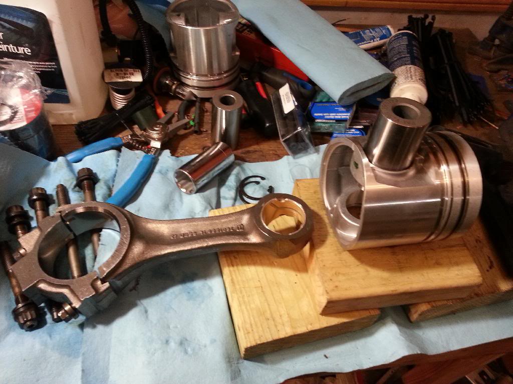
It's actually SUPER easy so long as you don't knock the wrist pin all the way out...
There, all done those!
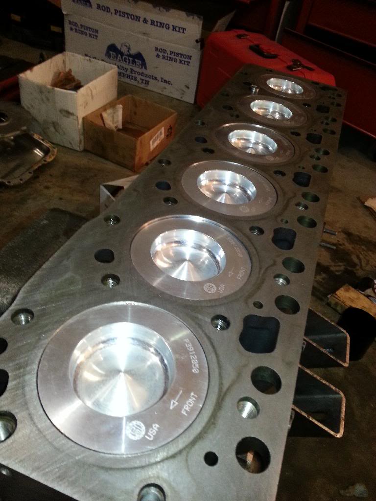
After that I checked the ring gap, no pictures for that either. but here are a couple of the cylinders for good measure
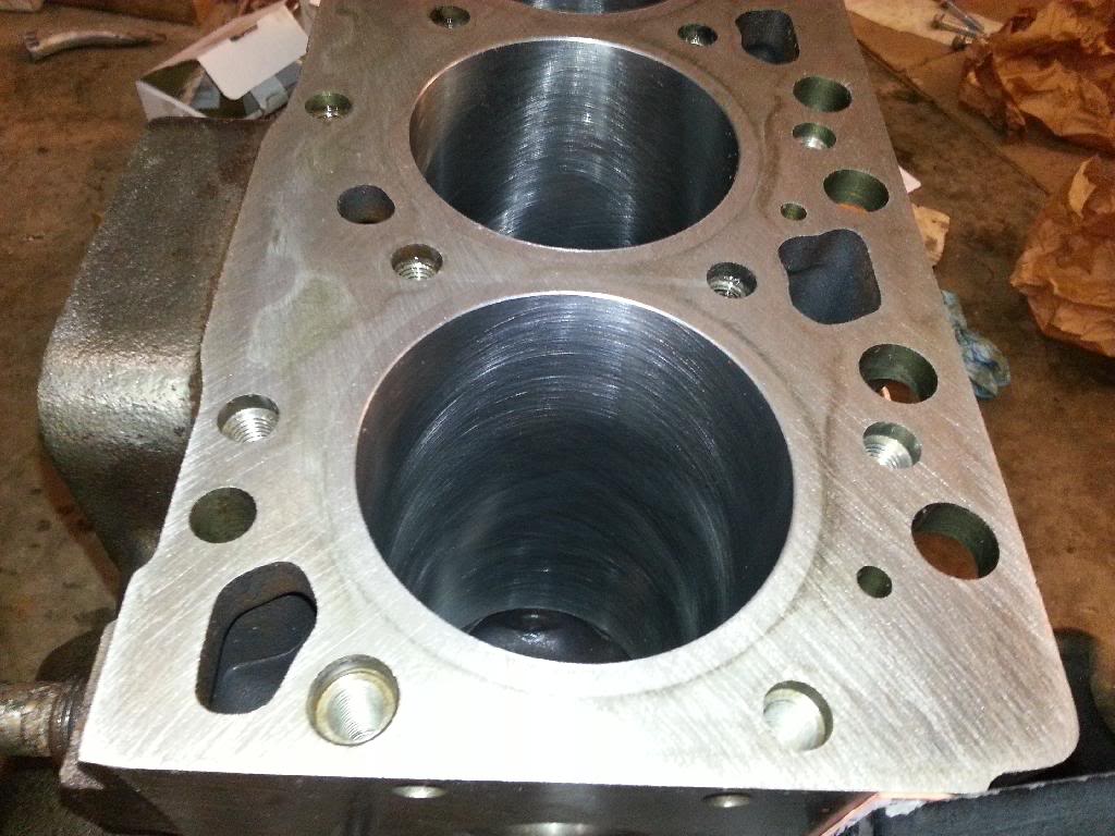
Fancy!
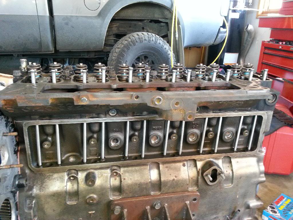
After that I used the trusty ring compressor and got all 6 pistons in.
from the back
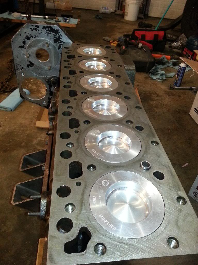
from the front
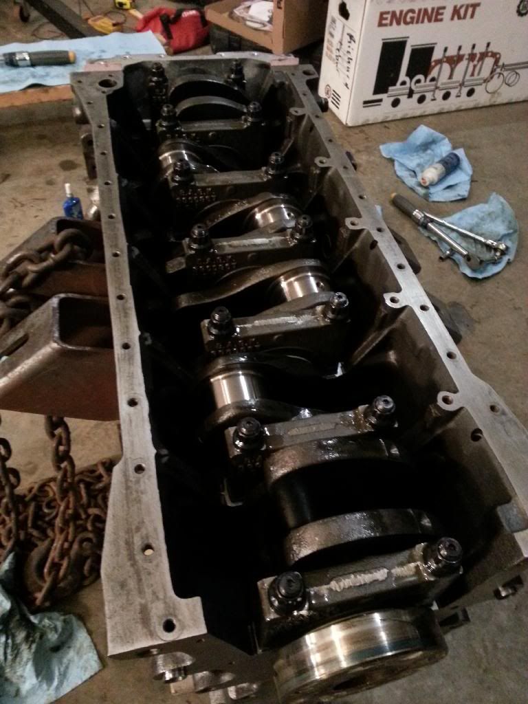
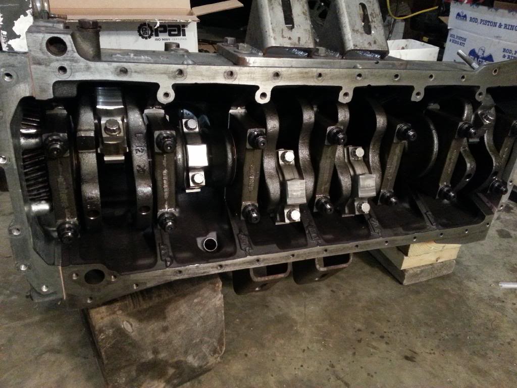
And then I rolled the block on it's side (which I did with great care this time!) so I could fasten the rods to the crank with the nice L19 ARP rod bolts!
There all done that!
And the last order of business on the night was getting the pan on. Now this might seem easy (and it is) but it sure takes a long time! First, I had to wash all 36 oil covered bolts one by one with varsol... Then since the block is on it's side I had to fight with the pan and gasket to get them on right, then I had to put all 36 bolts in and torque em down. (as a little note to those that don't know, where the timing case meets the block and where the rear main housing meets the block you have to put a little bit of black or gray gasket maker stuff to fill in any defects in the transition so it doesn't seep oil) And since I don't want it to leak, I took them out again one at a time after I gave em all one torque and used blue locktite and then put each one back in and torqued it down and then moved on to the next one... 36 times. Anyway... pretty much all the 10mm head bolts (m8x1.25) on the motor all torque down to 18ft/lbs. I tq them all down to 250 in/lbs (20.5ft/lbs). Not sure it actually makes a difference in helping keep the motor from leaking doing that but I feel better about it... whatever floats your boat right?
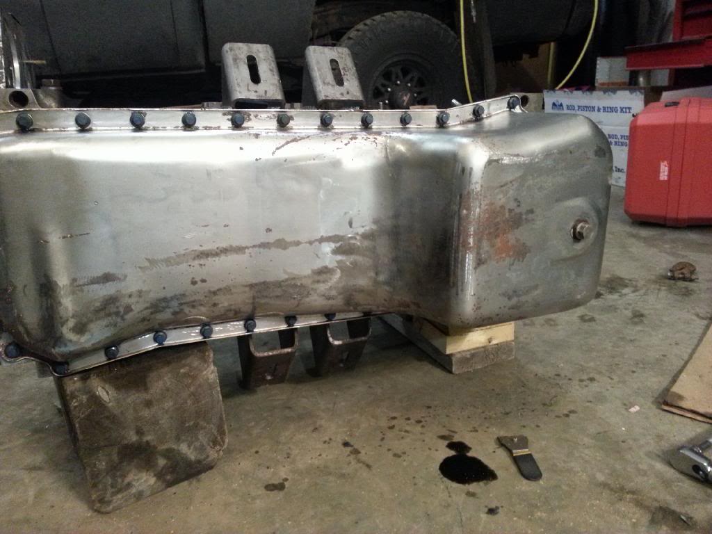
Soooo.... pans on and I'm done for the night...
Next on the list when I find time is assembling the head, finding true TDC with the degree wheel, putting the head on, then tappet cover likely, then injector pump and vac pump. All the most tedious stuff is all done now except maybe torquing the head down but that's not too bad really.
I'm done for the night! Tired. Been a long day
Ok as for tonights work...
First order of business was this little guy.
And by this little guy I mean the oil plug behind the cam. The guy at the machine shop that did the block work called me and told me he noticed that that particular plug was MIA. I said I didn't remove it, and he said he didn't remove it. Apparently at some point or another it got blown out? Come to think of it I sort of remember noticing a plug in the bottom of the pan when I disassembled the motor. That said, I'm not totally sure of that. And my oil pressure was fine when I took it apart so who knows...
anyways, I had to take out the cam retainer and pull the cam out a few inches to get at it properly. Fortunately for me I actually already had the plug because 2 years ago when I did the motor I bought the freeze plug kit but only did some of the plugs. Not that one though. after I got it in I got the cam back in place.
Second was getting the rear main seal and seal housing on. 7ft lbs on the 6 little bolts holding it in and that was done (no picture apparently)
Third order of business was installing the oil pump.
Then I had to some how roll the motor so I can deal with the pistons. I ended up dropping/rolling the whole **** thing right on to the concrete floor. I got lucky though, nothing was damaged
Next order of business was getting the pistons on the connecting rods. New wrist pin bushings were put in by the shop.
It's actually SUPER easy so long as you don't knock the wrist pin all the way out...
There, all done those!
After that I checked the ring gap, no pictures for that either. but here are a couple of the cylinders for good measure
Fancy!
After that I used the trusty ring compressor and got all 6 pistons in.
from the back
from the front
And then I rolled the block on it's side (which I did with great care this time!) so I could fasten the rods to the crank with the nice L19 ARP rod bolts!
There all done that!
And the last order of business on the night was getting the pan on. Now this might seem easy (and it is) but it sure takes a long time! First, I had to wash all 36 oil covered bolts one by one with varsol... Then since the block is on it's side I had to fight with the pan and gasket to get them on right, then I had to put all 36 bolts in and torque em down. (as a little note to those that don't know, where the timing case meets the block and where the rear main housing meets the block you have to put a little bit of black or gray gasket maker stuff to fill in any defects in the transition so it doesn't seep oil) And since I don't want it to leak, I took them out again one at a time after I gave em all one torque and used blue locktite and then put each one back in and torqued it down and then moved on to the next one... 36 times. Anyway... pretty much all the 10mm head bolts (m8x1.25) on the motor all torque down to 18ft/lbs. I tq them all down to 250 in/lbs (20.5ft/lbs). Not sure it actually makes a difference in helping keep the motor from leaking doing that but I feel better about it... whatever floats your boat right?
Soooo.... pans on and I'm done for the night...
Next on the list when I find time is assembling the head, finding true TDC with the degree wheel, putting the head on, then tappet cover likely, then injector pump and vac pump. All the most tedious stuff is all done now except maybe torquing the head down but that's not too bad really.
I'm done for the night! Tired. Been a long day
01-27-2014, 12:29 PM
#11
Registered User
Thread Starter
I can't remember the exact order of things.
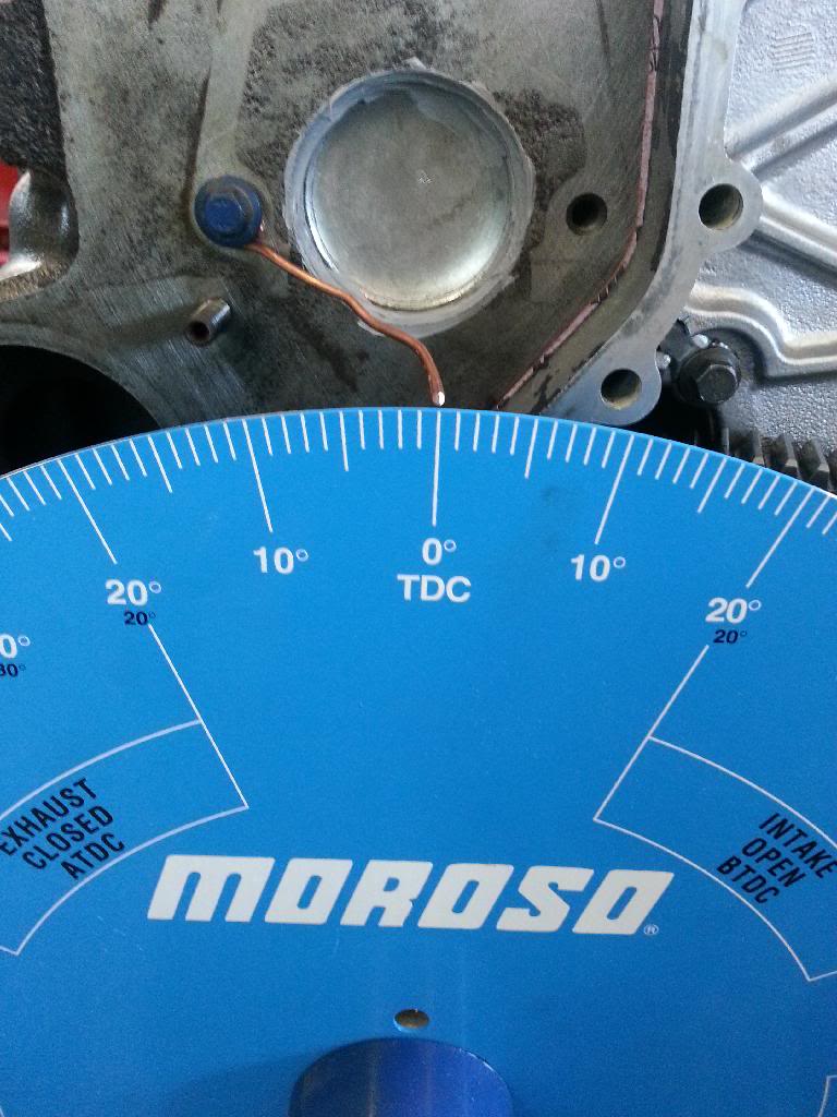
Pretty sure I started with finding TDCC#1
0 degrees on the wheel was 0.010" before TDC
Then 0.010" after TDC was at 9 degrees.
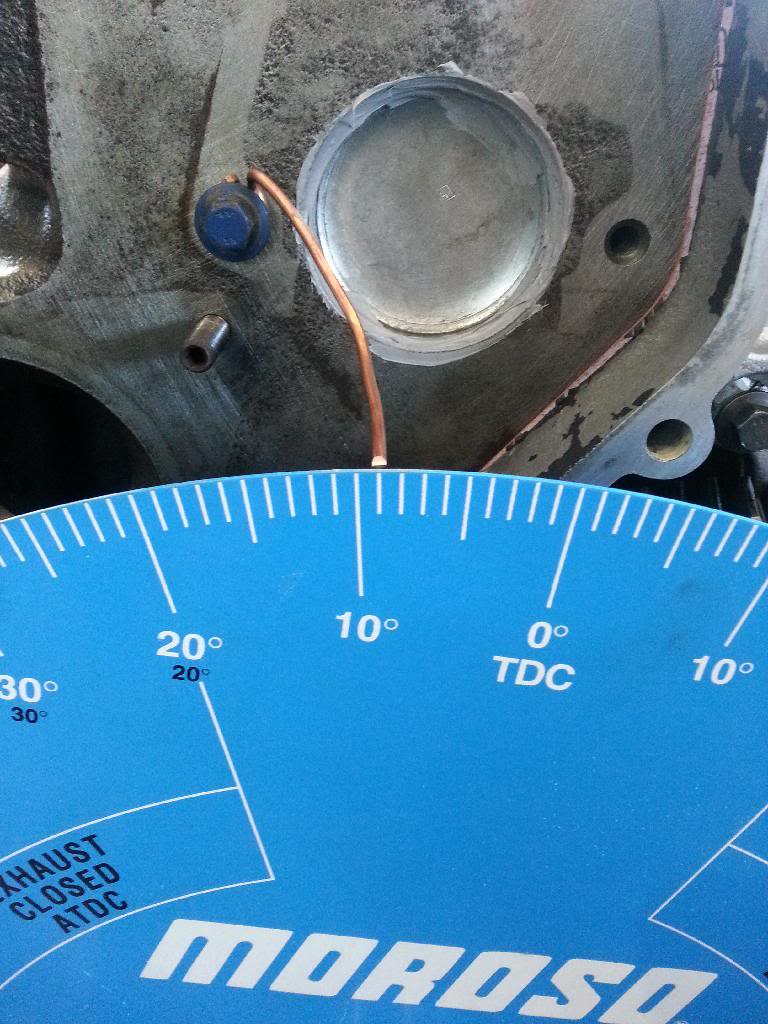
cut that in half and TDCC#1 is 4.5 Degrees so I rotated it to that and adjusted the wire to match after rotating to 4.5*
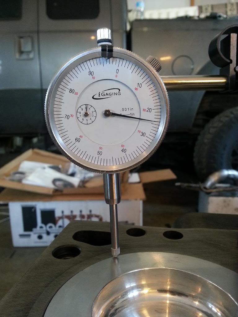
Next was checking piston protrusion
zeroed and set at the block deck level
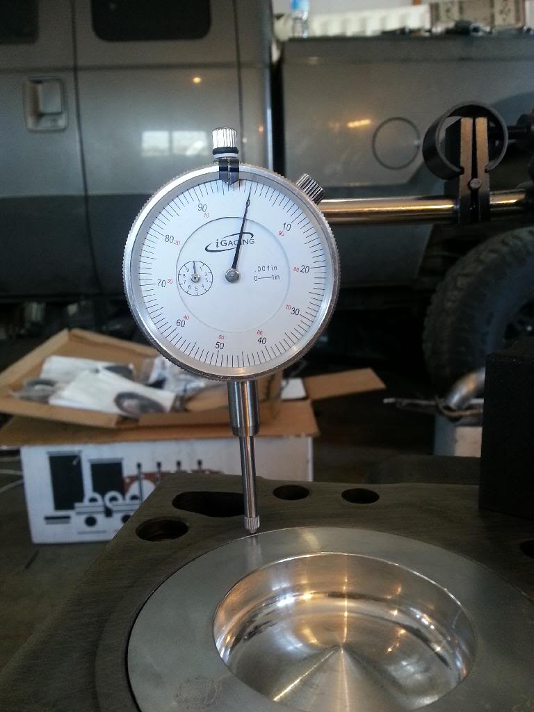
TDC - 0.024" piston protrusion. Because I'm using a less than desirable method of checking this I did it several times. Every time I got between 0.022-0.024". I went with the higher number for arguements sake. No suprises there. The block has been decked 0.010" in the past
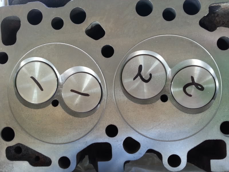
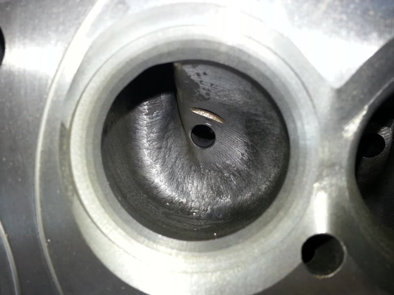
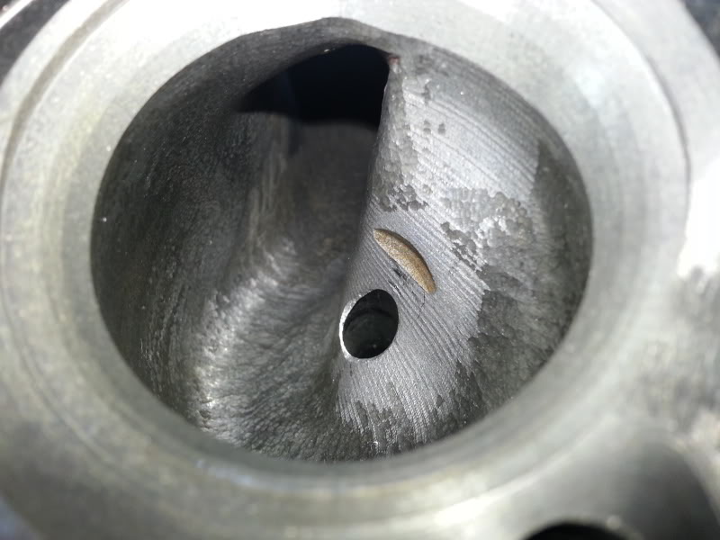
Now that's set let's move on to the head!
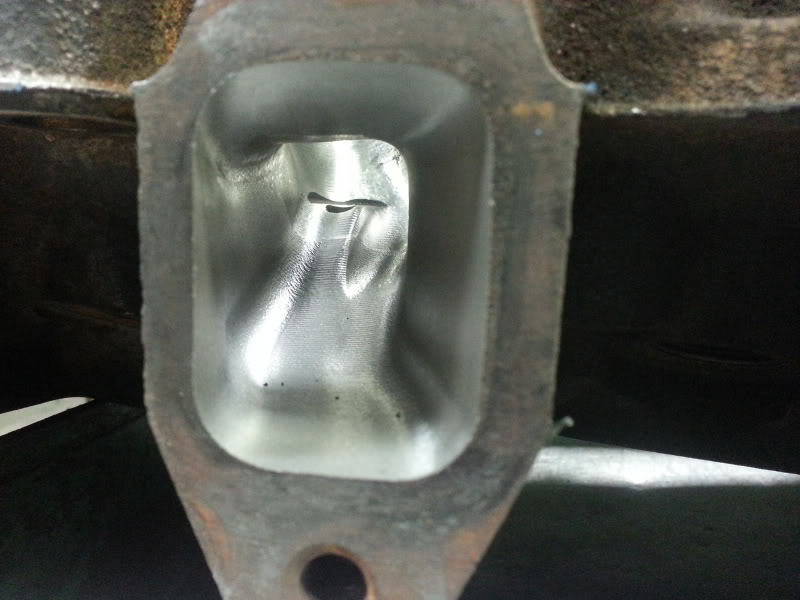
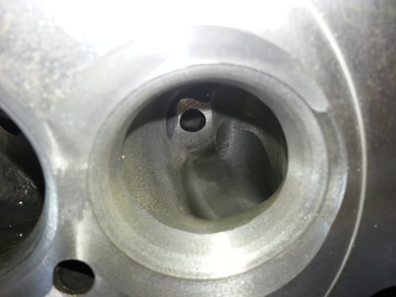
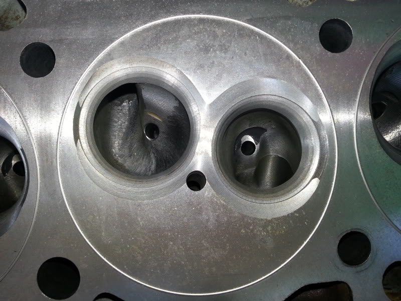
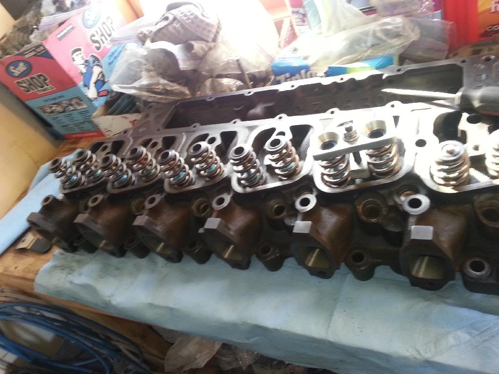
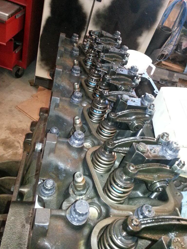
First I had to make sure everything was perfectly clean. As you all know this is a CTech head with larger valves.
This is a pic or 3 or 5 of the head work
Pretty sure I started with finding TDCC#1
0 degrees on the wheel was 0.010" before TDC
Then 0.010" after TDC was at 9 degrees.
cut that in half and TDCC#1 is 4.5 Degrees so I rotated it to that and adjusted the wire to match after rotating to 4.5*
Next was checking piston protrusion
zeroed and set at the block deck level
TDC - 0.024" piston protrusion. Because I'm using a less than desirable method of checking this I did it several times. Every time I got between 0.022-0.024". I went with the higher number for arguements sake. No suprises there. The block has been decked 0.010" in the past
Now that's set let's move on to the head!
First I had to make sure everything was perfectly clean. As you all know this is a CTech head with larger valves.
This is a pic or 3 or 5 of the head work
01-27-2014, 12:31 PM
#12
Registered User
Thread Starter
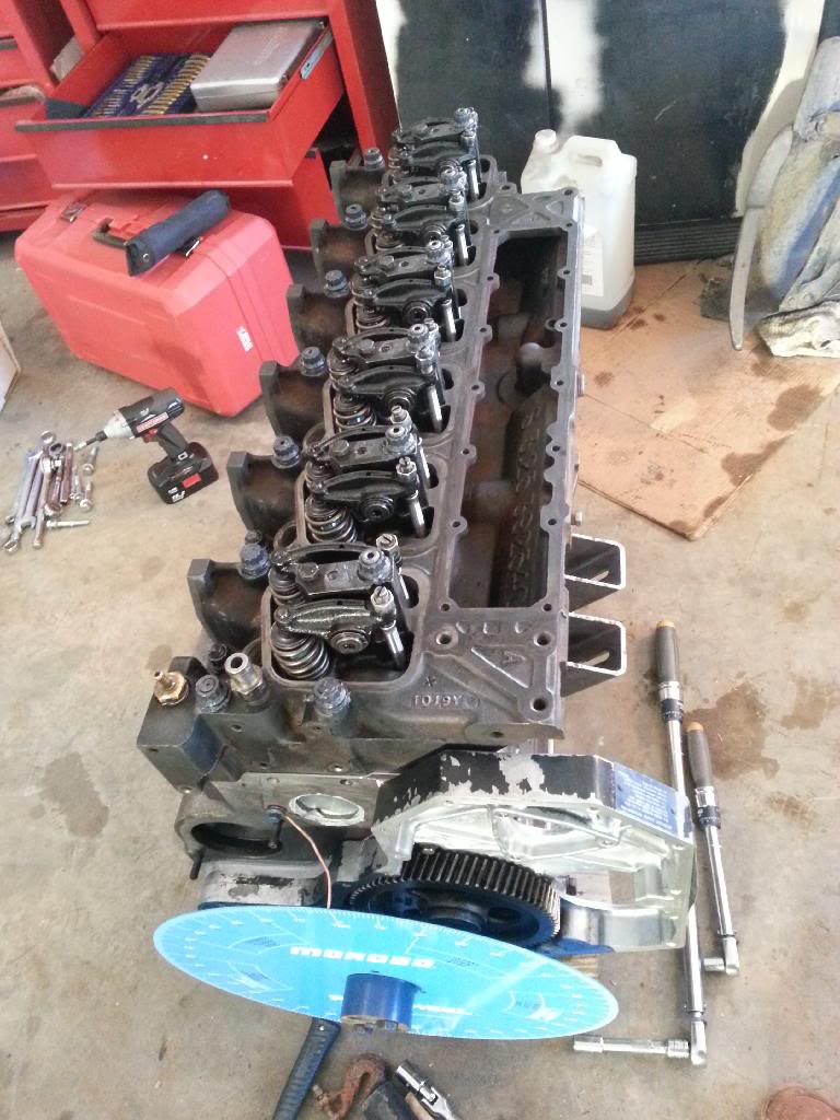
valves in and putting the top hat style stem seals in
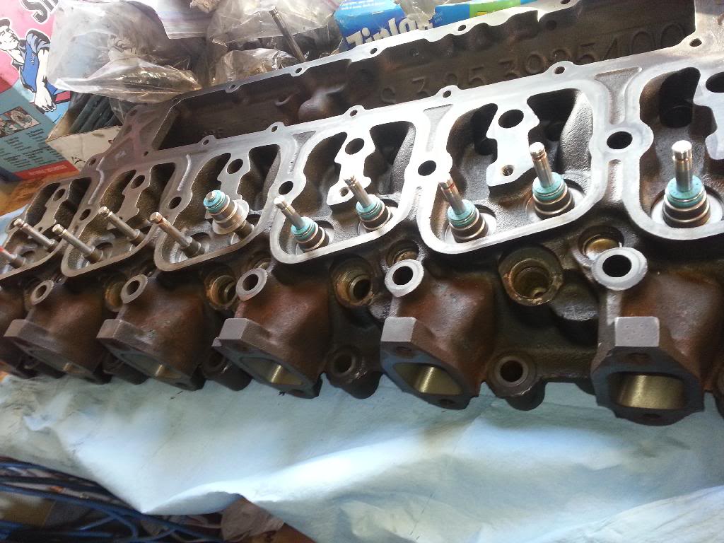
Getting the hamilton 165# springs and retainers/keepers in
I then checked valve depth on #1. Both were in the mid 0.050s" depth. CTech set them to a minimum of 0.055" depth so it's close.
Now that the head is assembled now is the time to prepare the block, make sure it's all clean and ready. install the allignment dowels and put the 0.010" Genuine cummins head gasket on. Then lay the head on and slide the hamilton HD pushrods in place.
Time to put the A1 Head studs in and use the ARP moly lube on them.
I torque them like this: 25lbs, 25lbs, 50lbs, 75lbs, 100lbs, 125lbs, 140lbs then I loosen each one off a small amount and retorque to 140lbs. There, all set. Head is on and in place. It's not going anywhere.
Set the valve lash. I set it to a conservative 0.012" intake and 0.024" exhaust for break in purposes. It will be reset after break in. Probably 0.08 intake and 0.015" exhaust.
Next up is checking intake centreline. I don't have a picture of this but for some reason I was getting 96* doing the .010 before and .010 after method. I then tried measuring the duration of max lift which was a little over 7* on the wheel. 95 to 102.5 was the duration of the peak of the lobe which puts me just shy of 99* centreline. I don't know why it kept giving me 96*... I guess that is my centreline. it's the same as it was on the motor before so it's staying the same now. Every time I was working with a right hand method turning the motor over to take up gear lash. whatever
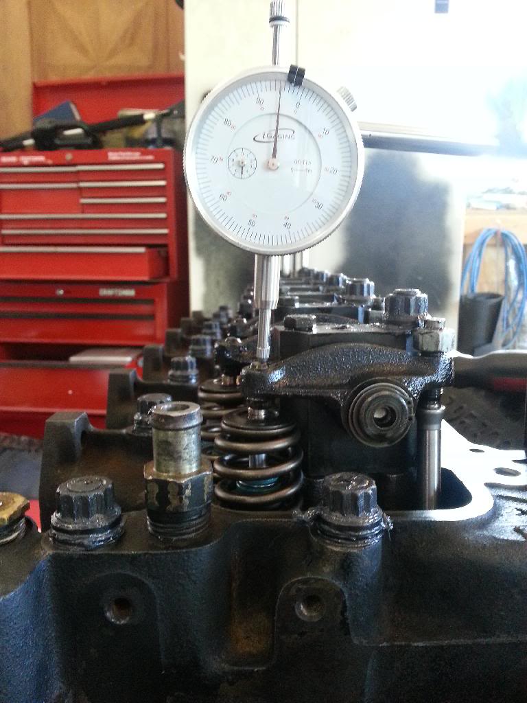
Let's check piston to valve clearance (note that I did this wrong on several levels. I put the motor at TDCC#1. Also I put the dial indicator on the rocker and it's supposed to be down on the retainer.)
The way I did it I have 0.105" clearance with the piston, but I did it wrong. Not worried, it should be well within spec anyways.
Next up was throwing the injectors in. Got em locked in with 50ft lbs. cummins book says 44 but I am reusing the old washers so a couple extra lbs won't hurt and will help em seal. These will be coming out when I get my 80lpm 155* bosch injectors in a month or so.
next was the billet tappet cover, lift pump and oil feed line for the vac/power steering pump
I called it quits saturday night after that. I'm really not sure what I want to do with the breathers... there isn't much room with the head for breathers and it leaks a lot of oil because it's not a good design and I do have a dual valve cover breather... I may plug these 2 holes in the tappet cover, I'm not sure yet...
Getting the hamilton 165# springs and retainers/keepers in
I then checked valve depth on #1. Both were in the mid 0.050s" depth. CTech set them to a minimum of 0.055" depth so it's close.
Now that the head is assembled now is the time to prepare the block, make sure it's all clean and ready. install the allignment dowels and put the 0.010" Genuine cummins head gasket on. Then lay the head on and slide the hamilton HD pushrods in place.
Time to put the A1 Head studs in and use the ARP moly lube on them.
I torque them like this: 25lbs, 25lbs, 50lbs, 75lbs, 100lbs, 125lbs, 140lbs then I loosen each one off a small amount and retorque to 140lbs. There, all set. Head is on and in place. It's not going anywhere.
Set the valve lash. I set it to a conservative 0.012" intake and 0.024" exhaust for break in purposes. It will be reset after break in. Probably 0.08 intake and 0.015" exhaust.
Next up is checking intake centreline. I don't have a picture of this but for some reason I was getting 96* doing the .010 before and .010 after method. I then tried measuring the duration of max lift which was a little over 7* on the wheel. 95 to 102.5 was the duration of the peak of the lobe which puts me just shy of 99* centreline. I don't know why it kept giving me 96*... I guess that is my centreline. it's the same as it was on the motor before so it's staying the same now. Every time I was working with a right hand method turning the motor over to take up gear lash. whatever
Let's check piston to valve clearance (note that I did this wrong on several levels. I put the motor at TDCC#1. Also I put the dial indicator on the rocker and it's supposed to be down on the retainer.)
The way I did it I have 0.105" clearance with the piston, but I did it wrong. Not worried, it should be well within spec anyways.
Next up was throwing the injectors in. Got em locked in with 50ft lbs. cummins book says 44 but I am reusing the old washers so a couple extra lbs won't hurt and will help em seal. These will be coming out when I get my 80lpm 155* bosch injectors in a month or so.
next was the billet tappet cover, lift pump and oil feed line for the vac/power steering pump
I called it quits saturday night after that. I'm really not sure what I want to do with the breathers... there isn't much room with the head for breathers and it leaks a lot of oil because it's not a good design and I do have a dual valve cover breather... I may plug these 2 holes in the tappet cover, I'm not sure yet...
 01-27-2014, 08:46 PM
#14
Registered User
Thread Starter
Believe it or not I don't have any. They've never flowed one with the intake still on with the bigger valves. I've asked twice and they said they would eventually get me one but it has yet to happen.
With the intake off (and full intake pnp) just upgrading to bigger valves from the smaller valves they said nets around 30cfm and I suppose I could have gotten them to email me that flow chart but that's not what I have so I never bothered.
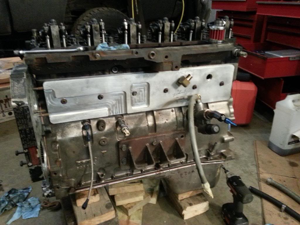
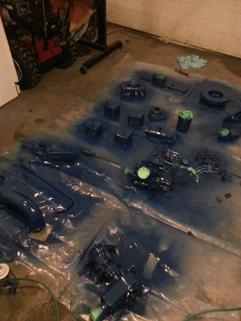
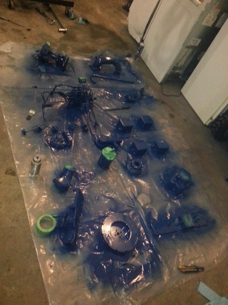
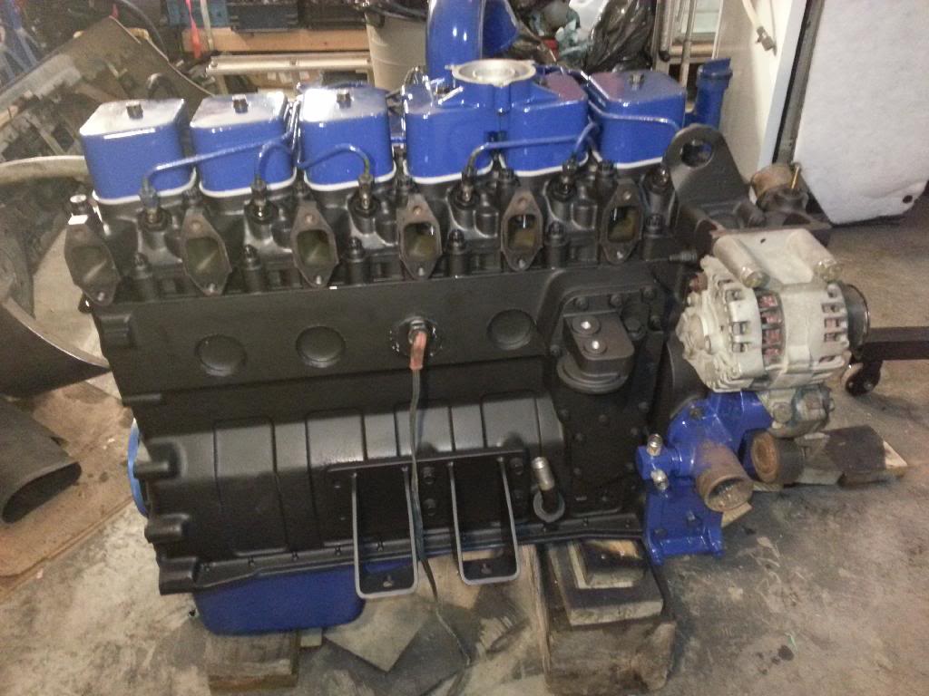
As for today I did a little bit of work. Just put the t.stat housing on. Put the rear loop thingymajig for lifting the motor on. Put the oil cooler on. What else... maybe that's it. I spent the majority of the time painting and prepping for paint. I'm a lot less meticulous this time around with painting everything than I was 2 years ago. I just don't have the time for it this time. I want it together and running too badly.
I can out of rattle can so I called it a night. Painting is basically done anyway. Had to use a respirator... save what few brain cells I have left
Progress pics.
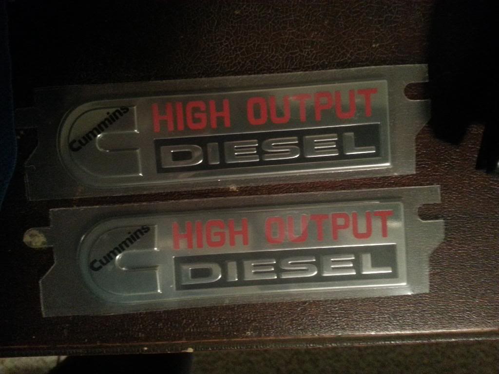
Oh and for christmas I got these for the rig too.
The Cummins badges are the 2011 dodge tailgate badges. They will replace my cummins badges on the fenders under the f250 badge. they are about 4" long and an inch wide
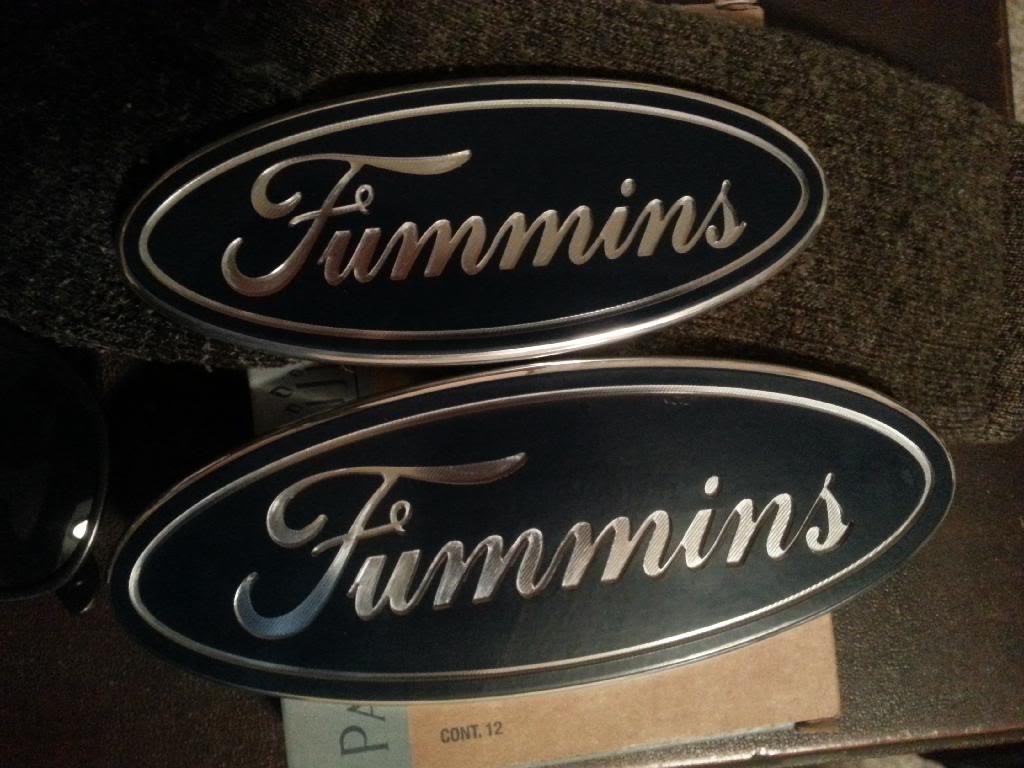
And I ordered these from Billet Badges. They are factory ford blue but for some reason the picture shows up black. I have no idea why... One replaces the tailgate ford badge and one replaces the grille badge.
With the intake off (and full intake pnp) just upgrading to bigger valves from the smaller valves they said nets around 30cfm and I suppose I could have gotten them to email me that flow chart but that's not what I have so I never bothered.
As for today I did a little bit of work. Just put the t.stat housing on. Put the rear loop thingymajig for lifting the motor on. Put the oil cooler on. What else... maybe that's it. I spent the majority of the time painting and prepping for paint. I'm a lot less meticulous this time around with painting everything than I was 2 years ago. I just don't have the time for it this time. I want it together and running too badly.
I can out of rattle can so I called it a night. Painting is basically done anyway. Had to use a respirator... save what few brain cells I have left
Progress pics.
Oh and for christmas I got these for the rig too.
The Cummins badges are the 2011 dodge tailgate badges. They will replace my cummins badges on the fenders under the f250 badge. they are about 4" long and an inch wide
And I ordered these from Billet Badges. They are factory ford blue but for some reason the picture shows up black. I have no idea why... One replaces the tailgate ford badge and one replaces the grille badge.
01-28-2014, 09:50 PM
#15
Registered User
Thread Starter
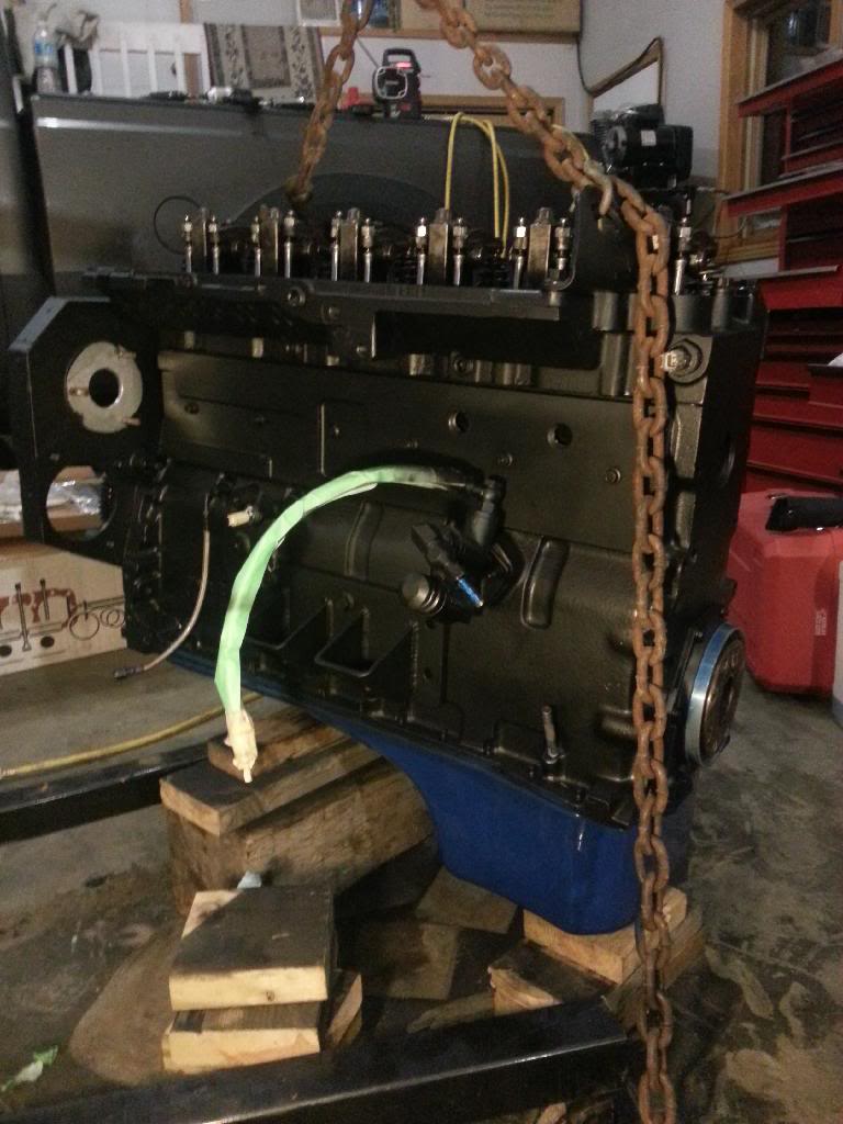
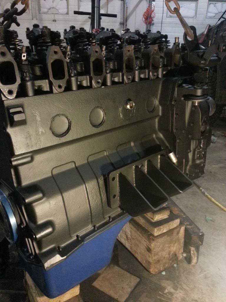
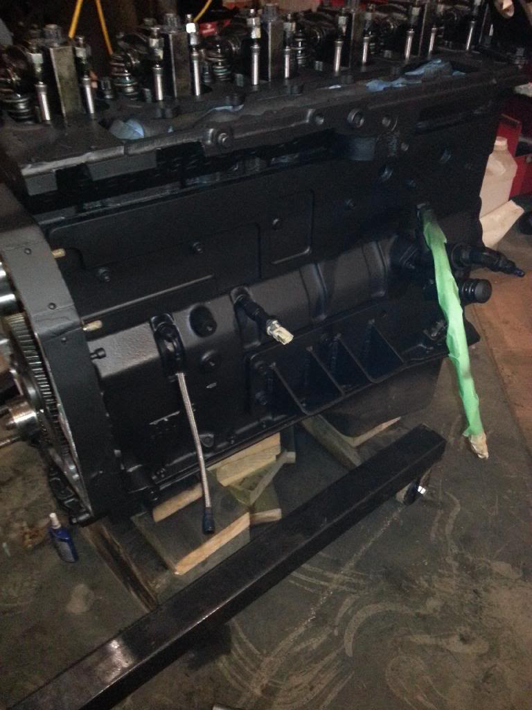
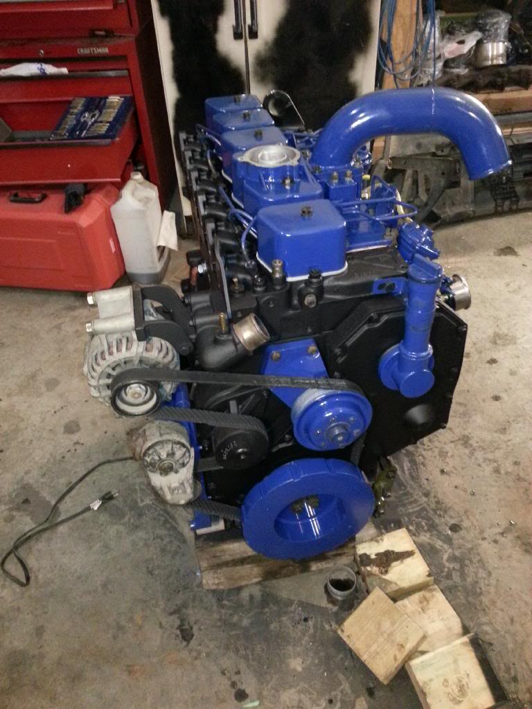
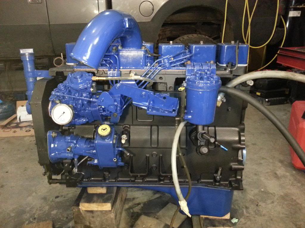
I'm starting to slack on the progress pictures but it's just cosmetic stuff left if you know what I mean.
I got the injector pump, all associated brackets, valve covers, injector lines, VAC pump, figuring out how to route the tappet cover vent tubes...
Got the timing cover all set and in place and the front main seal with a sleave for the crank (crank had some wear marks in it) Got the balancer on, the entire pulley system really. Got The oil fill tube on. The alternator. got the thingymajig on for the lower rad hose... No idea what it's called.
Only stuff that's left is the manifold, turbo and associated accessories. The flex plate and adapter plate also.
The motor stuff should be done tomorrow and then I'll have to tie up some loose ends on the truck. Mostly wiring, and I want (actually I don't want to, but I need to) to route and mount the pusher pump but I need to clean up a little before I go that far.
Progress pics from today.