Let's Screw-Up Your Steering Column With A New Tachometer and Gear Shifter!
 10-14-2007, 08:04 PM
#1
1st Generation Admin
Thread Starter
Well shoot! I'm where I can't justify NOT having a tachometer. With my recently rebuilding my heap's transmission, I need to dial-in the shift-points to better coincide with the engine's torque peak.
I'm also in the midst of sorting how I'm gonna do a fuel system pressure upgrade complete with fuel pressure gage.
Gutting my current engine gage set-up and doing it all over isn't out of the equation either.
I still need a tachometer though . . . . >cough<, . . . now.
So let's mount it on the steering column.
While we're at it, let's move the transmission's Over-Drive button from the dash, to the columns gear shifter. That will free up more dash space.
Why not! ?
With that, . . . . fire-Up your torches fellas, let's git to it!
As with any job of such ~ SAFETY FIRST!!
- Use safety glasses.
- Chock the wheels as is appropriate.
- Set your parking brake.
- Disconnect your battery's negative cable.
- Have a known working fire extinguisher within sight.
- Have a clean, uncluttered work area.
- Have good lighting.
I'm working on the Stock/OEM Dodge issue 1993 W250 ClubCab. Specifically the tilt-steering column and transmission OD switch. Another truck's mileage may vary.
Further, I'm using:
- 1 ISSPRO Tachometer (0~4000RPM, P/N ~ R5503).
- 1 Dodge 2nd Gen Automatic Transmission Column Shifter (includes built-in OD button w/associated wiring pig-tail, P/N 4690522AB).
- 1 Standard issue Dodge early 2nd Gen Steering Column Gage Pod (Shop around).
Alrighty then . . . . . .
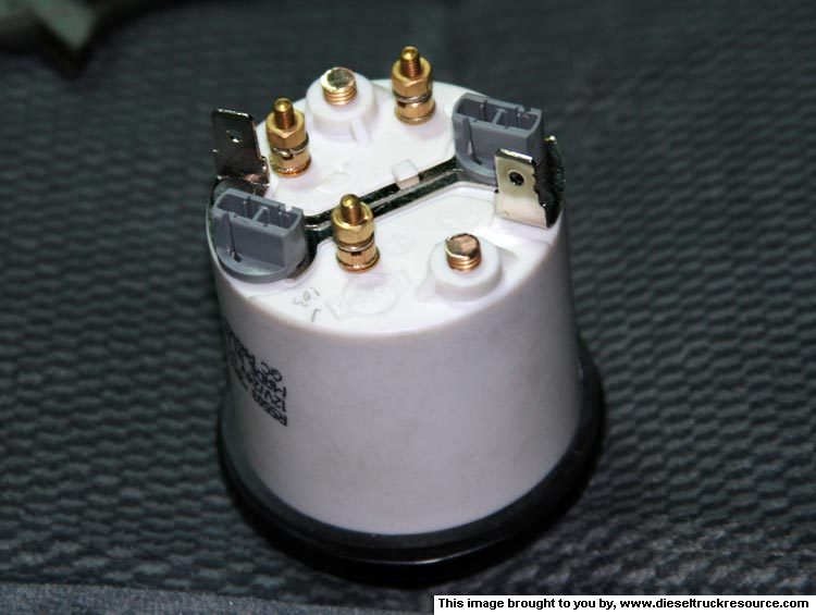
The gage I use comes with the typical mounting bracket and studs. This one is capable of working with a 24vdc system as well and has a "Voltage Reducing Resistor" to support such.
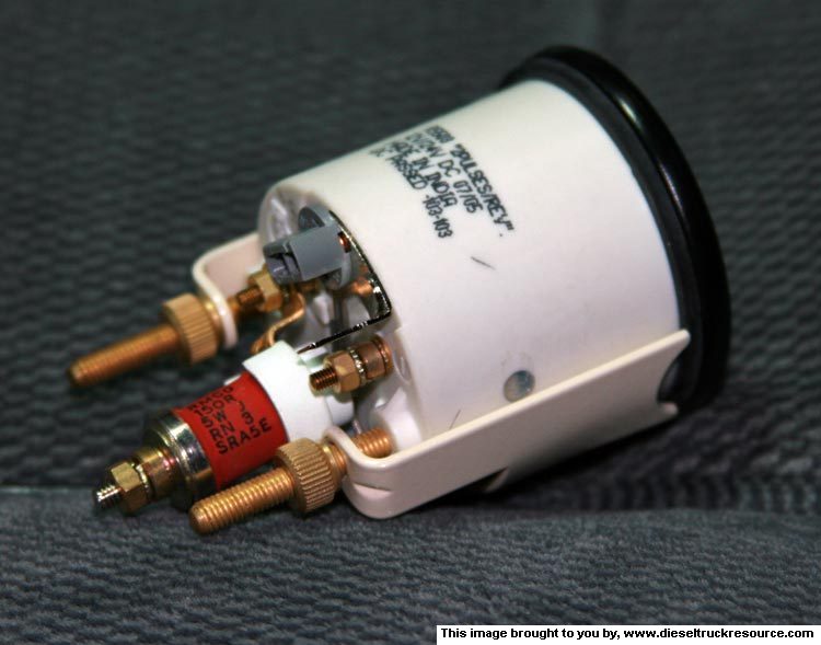
We'll need to remove all of it to fit in the column gage pod. Mine works with an "Interference Fit" to hold the gage.
If you haven't already, remove the steering column's covers (four pieces). Remove the small section of dash right there under the steering shaft as well. This will allow better access to the wiring under the dash.
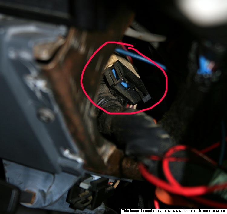
If you're gonna take advantage of the OEM/Factory provided tachometer wiring and plug, you'll most likely find it taped to the top of the big wiring harness that goes into the main fuse panel. Right where you can't see it from directly under the dash. DOH!!
(This is looking through the hole for the little dash panel under the steering column)
- OK, in my application, the wiring I'm using isn't factory bent for this install. We need to keep in mind that the cable will need to flex with the steering column when one is working the Tilt mechanism. Further, the cable needs to stay away from the Gear Selector mechanism. All so as to prevent the wires from being chewed, and the mechanisms from binding and such.
- The gage pod I'm using actually just nests on top of the OEM steering column cover (tiltable section). It's a universal type gage pod in that you get to figure out how you're gonna run the wires.
--> We need to consider all of this when routing the tachometer cable.
OK, fine.
I started by running the tachometer cable from under the dash, through the OEM/factory provided wiring shield tube thing up toward the steering wheel.

From there, I ran the cable behind the tilt mechanism, and forward between it and the gear selector mechanism. I formed bends in the cable where it needed to go around a corner so as to help the cable stay put.

I'm also in the midst of sorting how I'm gonna do a fuel system pressure upgrade complete with fuel pressure gage.
Gutting my current engine gage set-up and doing it all over isn't out of the equation either.
I still need a tachometer though . . . . >cough<, . . . now.
So let's mount it on the steering column.
While we're at it, let's move the transmission's Over-Drive button from the dash, to the columns gear shifter. That will free up more dash space.
Why not! ?
With that, . . . . fire-Up your torches fellas, let's git to it!
As with any job of such ~ SAFETY FIRST!!
- Use safety glasses.
- Chock the wheels as is appropriate.
- Set your parking brake.
- Disconnect your battery's negative cable.
- Have a known working fire extinguisher within sight.
- Have a clean, uncluttered work area.
- Have good lighting.
I'm working on the Stock/OEM Dodge issue 1993 W250 ClubCab. Specifically the tilt-steering column and transmission OD switch. Another truck's mileage may vary.
Further, I'm using:
- 1 ISSPRO Tachometer (0~4000RPM, P/N ~ R5503).
- 1 Dodge 2nd Gen Automatic Transmission Column Shifter (includes built-in OD button w/associated wiring pig-tail, P/N 4690522AB).
- 1 Standard issue Dodge early 2nd Gen Steering Column Gage Pod (Shop around).
NOTE: Not all tachometers are made the same. I'm using the OEM factory provided signal source. Some more universal gages allow you to simply mount a sensor on the vehicles alternator to get the engine RPM signal. BE SURE TO READ AND FOLLOW your tachometers manufactures installation instruction.
Alrighty then . . . . . .
The gage I use comes with the typical mounting bracket and studs. This one is capable of working with a 24vdc system as well and has a "Voltage Reducing Resistor" to support such.
We'll need to remove all of it to fit in the column gage pod. Mine works with an "Interference Fit" to hold the gage.
NOTE: Read the Pod's install instruction. Check the fit of your gage in the pod before you cut/trim/remove anything!
If you haven't already, remove the steering column's covers (four pieces). Remove the small section of dash right there under the steering shaft as well. This will allow better access to the wiring under the dash.
If you're gonna take advantage of the OEM/Factory provided tachometer wiring and plug, you'll most likely find it taped to the top of the big wiring harness that goes into the main fuse panel. Right where you can't see it from directly under the dash. DOH!!
(This is looking through the hole for the little dash panel under the steering column)
- OK, in my application, the wiring I'm using isn't factory bent for this install. We need to keep in mind that the cable will need to flex with the steering column when one is working the Tilt mechanism. Further, the cable needs to stay away from the Gear Selector mechanism. All so as to prevent the wires from being chewed, and the mechanisms from binding and such.
- The gage pod I'm using actually just nests on top of the OEM steering column cover (tiltable section). It's a universal type gage pod in that you get to figure out how you're gonna run the wires.
--> We need to consider all of this when routing the tachometer cable.
OK, fine.
I started by running the tachometer cable from under the dash, through the OEM/factory provided wiring shield tube thing up toward the steering wheel.
From there, I ran the cable behind the tilt mechanism, and forward between it and the gear selector mechanism. I formed bends in the cable where it needed to go around a corner so as to help the cable stay put.
 10-14-2007, 08:07 PM
#2
1st Generation Admin
Thread Starter
NOW STOP!
We need to eye-ball a few things so that we get it right the first time.
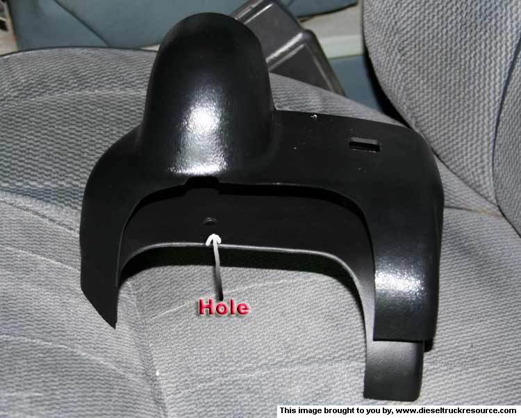
- I want a small hole just big enough for the cable and no more in the event the gage has to permanently come off.
- The hole needs to be where it will help hold the cable in the correct place when considering the steering column's inner workings.
I held the new pod/cover over the steering column, just above where it would nest, and marked where the hole needed to be in relation to the properly placed cable. A 1/4" hole is plenty big enough.
Looking at how it falls with the pod presents with this.
OK, fine. But let's stop with the tach install and do the trans OD column shifter thing . . . ..
It seems the later 1st Gen trucks share the same steering column as the '94 and up 2nd gens. This is what allows us to use the aforementioned gage pod, and further, the 2nd Gen version of the gear shift lever. It has the transmission's over-drive button built into the handle. Moving the switch there will allow one to mount a transmission oil temperature gage in place of the OEM OD button for example. KEWL!
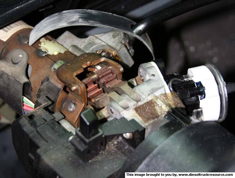
It's a very simple swap. Just GENTLY drift the shifters mounting pin from the bottom up. A couple of taps had mine pop right out.
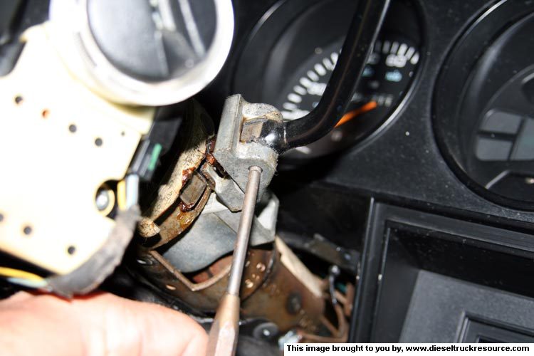
With the exception of the OD switch and associated pig-tail they're nearly identical.
(That with OD on top)
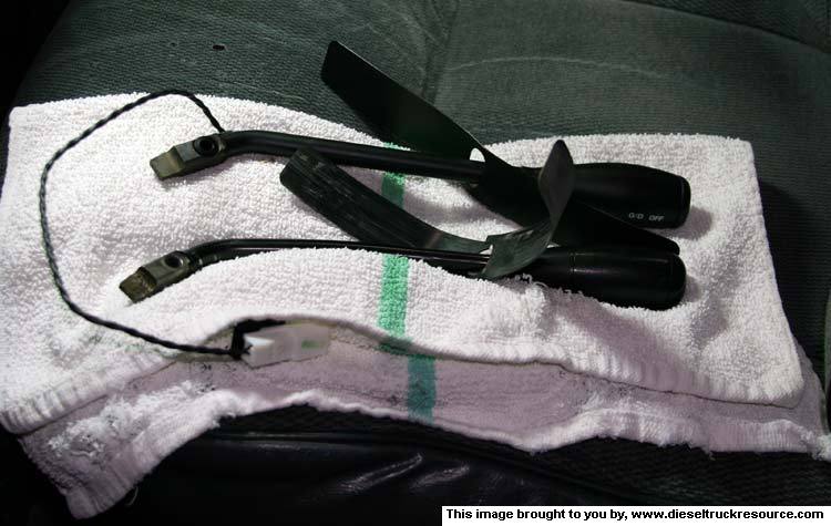
When installing the new shifter, you'll need to move the shifters spring forward a bit so as to properly engage the new shifter. With that, gently tap the mounting pin about flush.

- > The OD switch wiring will run forward, along the right side of the column. I found it necessary to cut off the OEM plug, and extend the two wires about eight inches so as to better reach the OEM OD switch wiring. It's best to do that now.
- Now you can assemble the lower section of the column cover. That being the section closest to the dash.
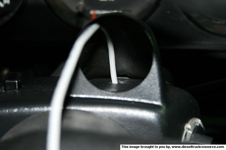
- Now pull the tachometer's cable up through the OEM column cover making sure the cable is in the proper place regarding the tilt/shifter guts. Tugging the cable from both ends will help nest the parts without a bunch of slack in the way.
- Nesting the new gage pod on top of the column should have the cable fall as such.
Now we need to affix the new gage pod to the OEM steering column cover. The Cover I used came with double-sided adhesive tape as well as four small plastic barbed pins. I chose the latter for a better fit.
- Using the plastic push-pins requires you to drill holes through the covers to lock them together. Be sure to drill where the pins won't interfere with the covers snap-locks and screw bosses and such.

- Completing that allows us to install the final bottom section of the column cover.
- Now we can connect the tachometer wiring. Refer to your tachometer's manufacturers wiring instructions.

- And install the gage itself. As my gage is a press-in type fit, I found it helpful to wrap a couple of layers of electrical tape around the gage body to make it fit right and stay put.
To finish the job, we need to make the final electrical connections.
Those running a tach that has you use a sensor on the alternator or crankshaft dampener need to go ahead and sort that out, else, you can use the same dash-light +12vdc power as well as the +12vdc switched power and common for powering your gage. READ, UNDERSTAND & FOLLOW your tachometer's wiring diagram.
The OEM factory tachometer plug offers the following:
- 18ga Black = +12vdc for gage lights
- 20ga Orange = 12vdc Common
- 18ga Red = Switched +12vdc
- 20ga Grey w/light blue tracer = Tachometer Signal From PCM
To connect the new OD shifter switch, find, cut and connect the new OD switch wires to the following wires from the OEM OD switch plug:
- 18ga Black = One side of the OD switch
- 20ga Orange w/white tracer = The other side of the OD switch.
NOTES:
1- You can connect the new OD switch in parallel with the OD switch and have both if you like.
2 - The remaining two wires are for the light that comes on when you work the switch. The new column shifter does not include a light. Sorry. Perhaps you can build it into a new custom information center.
Buttoning things up presents with the following.

We need to eye-ball a few things so that we get it right the first time.
- I want a small hole just big enough for the cable and no more in the event the gage has to permanently come off.
- The hole needs to be where it will help hold the cable in the correct place when considering the steering column's inner workings.
I held the new pod/cover over the steering column, just above where it would nest, and marked where the hole needed to be in relation to the properly placed cable. A 1/4" hole is plenty big enough.
Looking at how it falls with the pod presents with this.
OK, fine. But let's stop with the tach install and do the trans OD column shifter thing . . . ..
It seems the later 1st Gen trucks share the same steering column as the '94 and up 2nd gens. This is what allows us to use the aforementioned gage pod, and further, the 2nd Gen version of the gear shift lever. It has the transmission's over-drive button built into the handle. Moving the switch there will allow one to mount a transmission oil temperature gage in place of the OEM OD button for example. KEWL!
It's a very simple swap. Just GENTLY drift the shifters mounting pin from the bottom up. A couple of taps had mine pop right out.
With the exception of the OD switch and associated pig-tail they're nearly identical.
(That with OD on top)
When installing the new shifter, you'll need to move the shifters spring forward a bit so as to properly engage the new shifter. With that, gently tap the mounting pin about flush.
- > The OD switch wiring will run forward, along the right side of the column. I found it necessary to cut off the OEM plug, and extend the two wires about eight inches so as to better reach the OEM OD switch wiring. It's best to do that now.
- Now you can assemble the lower section of the column cover. That being the section closest to the dash.
- Now pull the tachometer's cable up through the OEM column cover making sure the cable is in the proper place regarding the tilt/shifter guts. Tugging the cable from both ends will help nest the parts without a bunch of slack in the way.
- Nesting the new gage pod on top of the column should have the cable fall as such.
Now we need to affix the new gage pod to the OEM steering column cover. The Cover I used came with double-sided adhesive tape as well as four small plastic barbed pins. I chose the latter for a better fit.
- Using the plastic push-pins requires you to drill holes through the covers to lock them together. Be sure to drill where the pins won't interfere with the covers snap-locks and screw bosses and such.
- Completing that allows us to install the final bottom section of the column cover.
- Now we can connect the tachometer wiring. Refer to your tachometer's manufacturers wiring instructions.
- And install the gage itself. As my gage is a press-in type fit, I found it helpful to wrap a couple of layers of electrical tape around the gage body to make it fit right and stay put.
To finish the job, we need to make the final electrical connections.
Those running a tach that has you use a sensor on the alternator or crankshaft dampener need to go ahead and sort that out, else, you can use the same dash-light +12vdc power as well as the +12vdc switched power and common for powering your gage. READ, UNDERSTAND & FOLLOW your tachometer's wiring diagram.
The OEM factory tachometer plug offers the following:
- 18ga Black = +12vdc for gage lights
- 20ga Orange = 12vdc Common
- 18ga Red = Switched +12vdc
- 20ga Grey w/light blue tracer = Tachometer Signal From PCM
Don't short any of these wires as you may very well permanently damage your PCM.
To connect the new OD shifter switch, find, cut and connect the new OD switch wires to the following wires from the OEM OD switch plug:
- 18ga Black = One side of the OD switch
- 20ga Orange w/white tracer = The other side of the OD switch.
NOTES:
1- You can connect the new OD switch in parallel with the OD switch and have both if you like.
2 - The remaining two wires are for the light that comes on when you work the switch. The new column shifter does not include a light. Sorry. Perhaps you can build it into a new custom information center.
Buttoning things up presents with the following.
10-14-2007, 08:08 PM
#3
1st Generation Admin
Thread Starter
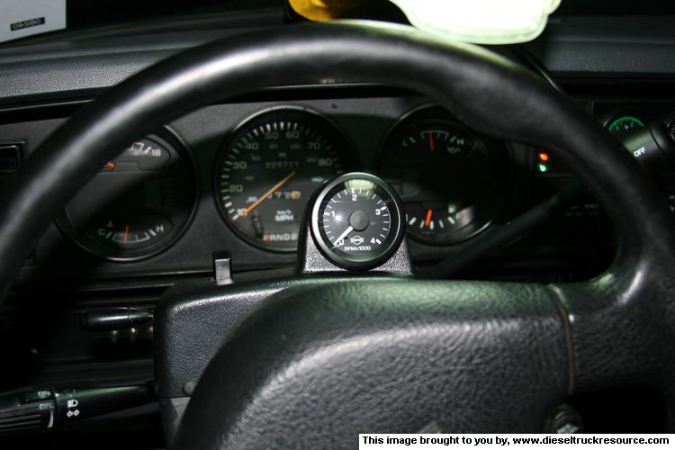
KEWL!! Now I can see where my transmission is shifting, and compared to a dyno chart, fine-tune said shift points.
Getting out into the field in the front yard, putting it in first gear and flooring it has the tach go to and stay at 3200RPM's. Whoda thunk!? LOL!!
Y'all drive careful.
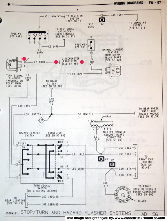
For those interested in such, here's the FSM wiring schematics relating to the factory provided tachometer plug as well as the OEM transmission OD switch.
-> The initial Tachometer plug and where the wires go from there (zoom in for a better view).
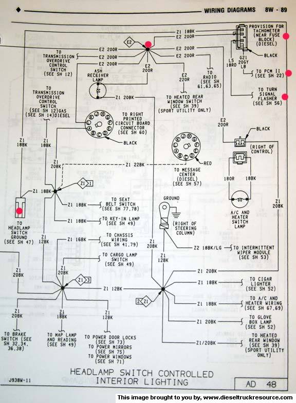
-> The Engine RPM signal wire from the PCM going to the plug (zoom in for a better view).

-> And the Switched +12vdc power going to the plug (zoom in for a better view).
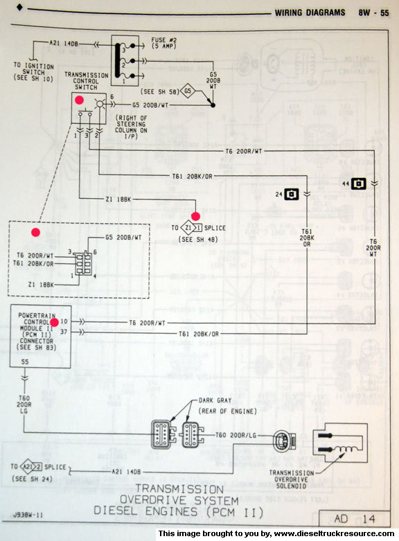
-> Here's how the transmission OEM overdrive switch is wired (zoom in for a better view).
Here's hoping these help.
Getting out into the field in the front yard, putting it in first gear and flooring it has the tach go to and stay at 3200RPM's. Whoda thunk!? LOL!!
Y'all drive careful.
For those interested in such, here's the FSM wiring schematics relating to the factory provided tachometer plug as well as the OEM transmission OD switch.
-> The initial Tachometer plug and where the wires go from there (zoom in for a better view).
-> The Engine RPM signal wire from the PCM going to the plug (zoom in for a better view).
-> And the Switched +12vdc power going to the plug (zoom in for a better view).
-> Here's how the transmission OEM overdrive switch is wired (zoom in for a better view).
Here's hoping these help.
Trending Topics
10-17-2007, 03:18 PM
#10
1st Generation Admin
Thread Starter
Thanks for the kind words folks. 
NOTE: If you're gonna run the ISSPRO gage that I have, do not waste your money on the ISSPRO adapter. To start with, the included instruction is backward in that it directs one to connect the 2 1/16" gage to the adapters white wire. As such the built-in filter component of the adapter is placed in the signal circuit.
Wired as such, the gage WILL NOT function.
The correct wiring has you connect the yellow wire which equates to a direct connection from the trucks PCM to the gage.
As such, the adapter amounts to an expensive 3' piece of four conductor wire with individual connectors on one end (NO molded plug for the OEM connector under the dash as some might think).
Save your money and use your own wire and connectors from Radio Shack.
10-17-2007, 05:47 PM
#11
Banned

Join Date: Jan 2004
Location: Cape Girardeau MO
Posts: 1,205
Likes: 0
Received 0 Likes
on
0 Posts
BUT, if you have the flat faced tach, you will need the adaptor kit. I think it was $20 or so from either Geno's Garage, or PDR. At least my tach didnt work without it.
Good write up, by the way.
Daniel
Good write up, by the way.
Daniel
10-18-2007, 04:13 AM
#14
Registered User
I thought the Issopro was too long to fit into that pod?
Based on this and with all this info I'll move my Issopro from its zip-tie mount into permanant housing!
Many thanks,
Based on this and with all this info I'll move my Issopro from its zip-tie mount into permanant housing!
Many thanks,
